EP1191286A2 - Oven provided with analyzer for the air present in its cooking chamber - Google Patents
Oven provided with analyzer for the air present in its cooking chamber Download PDFInfo
- Publication number
- EP1191286A2 EP1191286A2 EP01119207A EP01119207A EP1191286A2 EP 1191286 A2 EP1191286 A2 EP 1191286A2 EP 01119207 A EP01119207 A EP 01119207A EP 01119207 A EP01119207 A EP 01119207A EP 1191286 A2 EP1191286 A2 EP 1191286A2
- Authority
- EP
- European Patent Office
- Prior art keywords
- conduit
- oven
- analyzer
- cooking chamber
- suction
- Prior art date
- Legal status (The legal status is an assumption and is not a legal conclusion. Google has not performed a legal analysis and makes no representation as to the accuracy of the status listed.)
- Granted
Links
Images


Classifications
-
- F—MECHANICAL ENGINEERING; LIGHTING; HEATING; WEAPONS; BLASTING
- F24—HEATING; RANGES; VENTILATING
- F24C—DOMESTIC STOVES OR RANGES ; DETAILS OF DOMESTIC STOVES OR RANGES, OF GENERAL APPLICATION
- F24C15/00—Details
- F24C15/20—Removing cooking fumes
- F24C15/2007—Removing cooking fumes from oven cavities
-
- F—MECHANICAL ENGINEERING; LIGHTING; HEATING; WEAPONS; BLASTING
- F24—HEATING; RANGES; VENTILATING
- F24C—DOMESTIC STOVES OR RANGES ; DETAILS OF DOMESTIC STOVES OR RANGES, OF GENERAL APPLICATION
- F24C14/00—Stoves or ranges having self-cleaning provisions, e.g. continuous catalytic cleaning or electrostatic cleaning
- F24C14/02—Stoves or ranges having self-cleaning provisions, e.g. continuous catalytic cleaning or electrostatic cleaning pyrolytic type
Definitions
- the present invention relates to a domestic oven in accordance with the introduction to the main claim.
- Analyzers disposed within cavities of domestic ovens have been known for some time. These analyzers enable, for example, the state of preparation of food positioned in the cooking chamber or cavity of said ovens to be determined; alternatively or additionally, if said ovens are of the type in which pyrolytic cleaning (known per se) takes place, these analyzers enable the degree of completion of this cleaning to be determined by analyzing the gases generated within the cooking chamber during pyrolysis.
- gas analyzers can be of absorption spectrum analysis type or of catalytic/resistive type. They measure the content of CO, CO 2 , hydrocarbons (HC) and/or other gaseous compounds present in the cooking chamber, which can derive either from food cooking processes or from the pyrolytic cleaning process.
- Gas analyzers or sensors are used in those ovens in which here is no forced air circulation for cooling the oven.
- said analysis carried out in known manner, for example by modifying the resistivity or voltage of a component of such analyzers which is related to the absorption of a particular gaseous compound by these latter) is "read" by a usual member for controlling the oven operation; the pyrolytic cleaning is, for example, halted on the basis of this reading.
- An object of the present invention is therefore to provide an oven, preferably of built-in type, in which the composition of the air present in the cooking chamber can be analyzed, to enable the extent of cooking of a food present in said chamber or the state of advancement of pyrolytic cleaning (if the oven is prearranged for said cleaning) to be evaluated.
- a further object us to provide an oven in which the air in the cooking chamber can be analyzed reliably and at low cost.
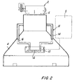
- a built-in oven comprises a cooking chamber or cavity 1 connected to a suction member defined by a tangential fan 2.
- the fan On its suction side the fan is connected via a conduit or channel 3 to the chamber 1 and via a conduit or channel 4 to an exit port B positioned on the upper side of the opening A of the chamber 1 so that the oven outer walls and the compartment in which the oven is mounted are cooled during oven operation.
- an electronic oven control member 5 In the interspace defined by said oven outer walls and by the compartment walls there is mounted on the oven an electronic oven control member 5, which is hence cooled by the gas drawn in by the fan 2.
- the conduits 3 and 4 converge into a conduit 6 directly connected downstream to the fan 2.
- a by-pass channel 11 is connected to the conduit 3 and leads to a gas analyzer 12 of known type.
- This analyzer is connected, via a usual connection member 13, to the oven control member 5 in such a manner as to enable this latter to obtain data on the analysis of the air leaving the cooking chamber 1 and to operate on the oven 1, for example by interrupting the heating of the chamber 1 because the food under preparation therein has reached the desired extent of cooking.
- the by-pass channel 11 comprises an outward conduit or branch 14 and a return conduit 16 connected respectively to the conduit 3 downstream of the catalyst 10 and to the conduit 6 upstream of the tangential fan 2.
- the effected analysis is "read" by the control member 5 which on the basis of this acts on the members heating the oven. If this latter is of the pyrolytic cleaning type, the aforesaid analysis can be carried out during this cleaning operation to enable the member 5 to halt the cleaning when suitable.
- the air leaving this latter is able to encounter the analyzer for a time necessary and sufficient for it to analyze its composition.
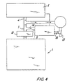
- the return channel or conduit 16 is not connected to the conduit 6, but to the discharge conduit 15 downstream of the fan 2 in the air flow direction shown by the arrows of this figure.
- the connection region between these conduits can be formed by suitably choosing the cross-section of the conduit 16 to enable the air present in the analyzer to remain therein for the time required for its analysis.
- a gas analyzer can be used safely and reliably within a built-in oven for controlling at least the preparation of the food therein; if the oven is of the type provided with a pyrolytic cleaning member, the invention also enables the cleaning operation to be controlled.
- a dedicated pump or fan (not shown) can be used to extract a determined gas throughput or to make it flow through the sensor.
- the solution according to the invention can be applied in both static and forced-circulation ovens.
Landscapes
- Engineering & Computer Science (AREA)
- Chemical & Material Sciences (AREA)
- Combustion & Propulsion (AREA)
- Mechanical Engineering (AREA)
- General Engineering & Computer Science (AREA)
- Chemical Kinetics & Catalysis (AREA)
- Sampling And Sample Adjustment (AREA)
- Optical Measuring Cells (AREA)
Abstract
Description
Claims (6)
- An oven comprising an internal cavity or cooking chamber (1) connected to a suction conduit (3) operationally connected to a suction member (2) arranged to withdraw air from the interior of the cooking chamber (1) and to expel it into the environment in which the oven is positioned via a discharge conduit (15), characterised by comprising an analyzer (12) for the air drawn from the cooking chamber (1), said analyzer (12) being positioned within a by-pass conduit (11) connected to the suction conduit (3).
- An oven as claimed in claim 1, characterised in that the by- pass conduit (11) has a first branch (14) connecting the suction conduit (3) to the analyzer (12) and a return second branch (16) leaving the analyzer.
- An oven as claimed in claim 2, characterised in that the return second branch (16) is connected, at its entry, to the suction member (2).
- An oven as claimed in claim 3, characterised in that the return second branch (16) is connected to an entry conduit (6) to the suction member (2), there being connected to said conduit (6) a conduit (4) connected to an oven control member (5) arranged to cool the oven.
- An oven as claimed in claim 2, characterised in that the return second branch (16) is connected to the discharge conduit (15) leaving the suction member (2), there arriving at this member an entry conduit (6) to which there are connected the suction conduit (3) and a conduit (6) connected to an oven control member (5) arranged to cool the oven.
- An oven as claimed in claim 1, characterised in that the by- pass conduit (11) is connected at its exit to an auxiliary pump or fan arranged to feed a determined gas throughput through the analyzer (12).
Applications Claiming Priority (2)
| Application Number | Priority Date | Filing Date | Title |
|---|---|---|---|
| ITMI000530 | 2000-03-15 | ||
| IT2000MI000530U IT250446Y1 (en) | 2000-09-20 | 2000-09-20 | OVEN PROVIDED WITH AN AIR ANALYZER PRESENT IN ITS COOKING CHAMBER |
Publications (3)
| Publication Number | Publication Date |
|---|---|
| EP1191286A2 true EP1191286A2 (en) | 2002-03-27 |
| EP1191286A3 EP1191286A3 (en) | 2006-05-24 |
| EP1191286B1 EP1191286B1 (en) | 2008-10-08 |
Family
ID=11444465
Family Applications (1)
| Application Number | Title | Priority Date | Filing Date |
|---|---|---|---|
| EP01119207A Expired - Lifetime EP1191286B1 (en) | 2000-09-20 | 2001-08-09 | Oven provided with analyzer for the air present in its cooking chamber |
Country Status (4)
| Country | Link |
|---|---|
| EP (1) | EP1191286B1 (en) |
| DE (1) | DE60136043D1 (en) |
| ES (1) | ES2313923T3 (en) |
| IT (1) | IT250446Y1 (en) |
Cited By (2)
| Publication number | Priority date | Publication date | Assignee | Title |
|---|---|---|---|---|
| DE102010060821A1 (en) * | 2010-11-26 | 2012-05-31 | Rational Ag | Cooking appliance has measuring device having sensors arranged in pressure chamber for determining absorption of propagating electromagnetic radiation in certain spectral range by atmosphere in inner space |
| EP2469184A1 (en) * | 2010-12-23 | 2012-06-27 | Miele & Cie. KG | Cooking device and method for operating same |
Family Cites Families (3)
| Publication number | Priority date | Publication date | Assignee | Title |
|---|---|---|---|---|
| JPS57120032A (en) * | 1981-01-19 | 1982-07-26 | Toshiba Corp | Heating cooker |
| JPS58150720A (en) * | 1982-03-02 | 1983-09-07 | Matsushita Electric Ind Co Ltd | Composite cooker |
| US4481404A (en) * | 1982-12-22 | 1984-11-06 | General Electric Company | Turn-off control circuit for self-cleaning ovens |
-
2000
- 2000-09-20 IT IT2000MI000530U patent/IT250446Y1/en active
-
2001
- 2001-08-09 ES ES01119207T patent/ES2313923T3/en not_active Expired - Lifetime
- 2001-08-09 DE DE60136043T patent/DE60136043D1/en not_active Expired - Lifetime
- 2001-08-09 EP EP01119207A patent/EP1191286B1/en not_active Expired - Lifetime
Cited By (2)
| Publication number | Priority date | Publication date | Assignee | Title |
|---|---|---|---|---|
| DE102010060821A1 (en) * | 2010-11-26 | 2012-05-31 | Rational Ag | Cooking appliance has measuring device having sensors arranged in pressure chamber for determining absorption of propagating electromagnetic radiation in certain spectral range by atmosphere in inner space |
| EP2469184A1 (en) * | 2010-12-23 | 2012-06-27 | Miele & Cie. KG | Cooking device and method for operating same |
Also Published As
| Publication number | Publication date |
|---|---|
| ITMI20000530U1 (en) | 2002-03-20 |
| DE60136043D1 (en) | 2008-11-20 |
| EP1191286A3 (en) | 2006-05-24 |
| EP1191286B1 (en) | 2008-10-08 |
| ES2313923T3 (en) | 2009-03-16 |
| IT250446Y1 (en) | 2003-09-10 |
| ITMI20000530V0 (en) | 2000-09-20 |
Similar Documents
| Publication | Publication Date | Title |
|---|---|---|
| JP7022777B2 (en) | Dust-containing industry Systems and methods for analyzing the chemical composition of off-gas | |
| EP2669583B1 (en) | Cooking oven with vapor treatment system | |
| US10317318B2 (en) | Exhaust-gas sampling system, and method for operating an exhaust-gas sampling system of said type | |
| US6042634A (en) | Moisture extractor system for gas sampling | |
| CA2463260C (en) | Apparatus and method for exhausting pollutant in microwave oven | |
| US20050224490A1 (en) | Smokeless vent system for a cooking appliance | |
| CN113685871B (en) | Control method and device for oil fume extraction equipment and oil fume extraction system | |
| EP1191286B1 (en) | Oven provided with analyzer for the air present in its cooking chamber | |
| DE59505106D1 (en) | Device for removing vapors from an oven | |
| US8469017B2 (en) | Baking oven with a vapor channel in which a catalyst and a gas sensor are arranged | |
| US4320275A (en) | Microwave oven with resistance heating unit | |
| CA1218117A (en) | Food emission sensing | |
| EP0344639B1 (en) | Thermally switchable katharometer | |
| JP3203608B2 (en) | Gas-in-oil analyzer | |
| US5872305A (en) | Method for preparing a test gas stream | |
| JP2000036283A (en) | Mass spectrometer | |
| JP2005147683A (en) | Sample pretreatment equipment | |
| CN213456819U (en) | Waste gas monitoring device | |
| JP2816870B2 (en) | Purging device for odor detection element | |
| EP0651946B1 (en) | Method and apparatus for controlling the composition of a gaseous mixture in a space | |
| JP4653357B2 (en) | Method and apparatus for analyzing metal carbonyl compound | |
| CN112426025B (en) | Exhaust control method of cooking equipment after cooking is finished and cooking equipment | |
| EP0739650A3 (en) | Evacuating system with off-gas cleaning and process for operating it | |
| CN210740779U (en) | Variable-frequency flue gas condenser and continuous flue gas emission monitoring system | |
| JP2010066035A (en) | Gas chromatograph |
Legal Events
| Date | Code | Title | Description |
|---|---|---|---|
| PUAI | Public reference made under article 153(3) epc to a published international application that has entered the european phase |
Free format text: ORIGINAL CODE: 0009012 |
|
| AK | Designated contracting states |
Kind code of ref document: A2 Designated state(s): AT BE CH CY DE DK ES FI FR GB GR IE IT LI LU MC NL PT SE TR |
|
| AX | Request for extension of the european patent |
Free format text: AL;LT;LV;MK;RO;SI |
|
| PUAL | Search report despatched |
Free format text: ORIGINAL CODE: 0009013 |
|
| AK | Designated contracting states |
Kind code of ref document: A3 Designated state(s): AT BE CH CY DE DK ES FI FR GB GR IE IT LI LU MC NL PT SE TR |
|
| AX | Request for extension of the european patent |
Extension state: AL LT LV MK RO SI |
|
| RIC1 | Information provided on ipc code assigned before grant |
Ipc: F24C 7/08 20060101AFI20011219BHEP Ipc: F24C 15/20 20060101ALI20060406BHEP Ipc: F24C 14/02 20060101ALI20060406BHEP |
|
| 17P | Request for examination filed |
Effective date: 20061026 |
|
| AKX | Designation fees paid |
Designated state(s): DE ES FR GB IT |
|
| 17Q | First examination report despatched |
Effective date: 20070314 |
|
| GRAP | Despatch of communication of intention to grant a patent |
Free format text: ORIGINAL CODE: EPIDOSNIGR1 |
|
| GRAS | Grant fee paid |
Free format text: ORIGINAL CODE: EPIDOSNIGR3 |
|
| GRAA | (expected) grant |
Free format text: ORIGINAL CODE: 0009210 |
|
| AK | Designated contracting states |
Kind code of ref document: B1 Designated state(s): DE ES FR GB IT |
|
| REG | Reference to a national code |
Ref country code: GB Ref legal event code: FG4D |
|
| REF | Corresponds to: |
Ref document number: 60136043 Country of ref document: DE Date of ref document: 20081120 Kind code of ref document: P |
|
| REG | Reference to a national code |
Ref country code: ES Ref legal event code: FG2A Ref document number: 2313923 Country of ref document: ES Kind code of ref document: T3 |
|
| PLBE | No opposition filed within time limit |
Free format text: ORIGINAL CODE: 0009261 |
|
| STAA | Information on the status of an ep patent application or granted ep patent |
Free format text: STATUS: NO OPPOSITION FILED WITHIN TIME LIMIT |
|
| 26N | No opposition filed |
Effective date: 20090709 |
|
| REG | Reference to a national code |
Ref country code: FR Ref legal event code: PLFP Year of fee payment: 16 |
|
| PGFP | Annual fee paid to national office [announced via postgrant information from national office to epo] |
Ref country code: DE Payment date: 20160802 Year of fee payment: 16 Ref country code: GB Payment date: 20160803 Year of fee payment: 16 Ref country code: IT Payment date: 20160822 Year of fee payment: 16 |
|
| PGFP | Annual fee paid to national office [announced via postgrant information from national office to epo] |
Ref country code: FR Payment date: 20160712 Year of fee payment: 16 |
|
| PGFP | Annual fee paid to national office [announced via postgrant information from national office to epo] |
Ref country code: ES Payment date: 20160712 Year of fee payment: 16 |
|
| REG | Reference to a national code |
Ref country code: DE Ref legal event code: R119 Ref document number: 60136043 Country of ref document: DE |
|
| GBPC | Gb: european patent ceased through non-payment of renewal fee |
Effective date: 20170809 |
|
| REG | Reference to a national code |
Ref country code: FR Ref legal event code: ST Effective date: 20180430 |
|
| PG25 | Lapsed in a contracting state [announced via postgrant information from national office to epo] |
Ref country code: GB Free format text: LAPSE BECAUSE OF NON-PAYMENT OF DUE FEES Effective date: 20170809 Ref country code: DE Free format text: LAPSE BECAUSE OF NON-PAYMENT OF DUE FEES Effective date: 20180301 |
|
| PG25 | Lapsed in a contracting state [announced via postgrant information from national office to epo] |
Ref country code: IT Free format text: LAPSE BECAUSE OF NON-PAYMENT OF DUE FEES Effective date: 20170809 Ref country code: FR Free format text: LAPSE BECAUSE OF NON-PAYMENT OF DUE FEES Effective date: 20170831 |
|
| REG | Reference to a national code |
Ref country code: ES Ref legal event code: FD2A Effective date: 20181025 |
|
| PG25 | Lapsed in a contracting state [announced via postgrant information from national office to epo] |
Ref country code: ES Free format text: LAPSE BECAUSE OF NON-PAYMENT OF DUE FEES Effective date: 20170810 |