EP1191284A2 - Vorrichtung zur Raumheizung - Google Patents
Vorrichtung zur Raumheizung Download PDFInfo
- Publication number
- EP1191284A2 EP1191284A2 EP01122804A EP01122804A EP1191284A2 EP 1191284 A2 EP1191284 A2 EP 1191284A2 EP 01122804 A EP01122804 A EP 01122804A EP 01122804 A EP01122804 A EP 01122804A EP 1191284 A2 EP1191284 A2 EP 1191284A2
- Authority
- EP
- European Patent Office
- Prior art keywords
- transferring
- brazier
- hearth
- combustion
- fuel materials
- Prior art date
- Legal status (The legal status is an assumption and is not a legal conclusion. Google has not performed a legal analysis and makes no representation as to the accuracy of the status listed.)
- Withdrawn
Links
- 238000010438 heat treatment Methods 0.000 title claims abstract description 16
- 238000002485 combustion reaction Methods 0.000 claims abstract description 31
- 239000000446 fuel Substances 0.000 claims abstract description 24
- 239000000463 material Substances 0.000 claims abstract description 23
- 230000001737 promoting effect Effects 0.000 claims abstract description 12
- 238000006073 displacement reaction Methods 0.000 claims abstract description 7
- 239000008188 pellet Substances 0.000 description 12
- 239000004449 solid propellant Substances 0.000 description 11
- 238000004140 cleaning Methods 0.000 description 5
- 239000000047 product Substances 0.000 description 5
- 238000012423 maintenance Methods 0.000 description 3
- 239000002023 wood Substances 0.000 description 3
- 238000006467 substitution reaction Methods 0.000 description 2
- QVGXLLKOCUKJST-UHFFFAOYSA-N atomic oxygen Chemical compound [O] QVGXLLKOCUKJST-UHFFFAOYSA-N 0.000 description 1
- 238000007664 blowing Methods 0.000 description 1
- 230000006735 deficit Effects 0.000 description 1
- 238000013508 migration Methods 0.000 description 1
- 230000005012 migration Effects 0.000 description 1
- 229910052760 oxygen Inorganic materials 0.000 description 1
- 239000001301 oxygen Substances 0.000 description 1
- 239000012265 solid product Substances 0.000 description 1
Images


Classifications
-
- F—MECHANICAL ENGINEERING; LIGHTING; HEATING; WEAPONS; BLASTING
- F23—COMBUSTION APPARATUS; COMBUSTION PROCESSES
- F23K—FEEDING FUEL TO COMBUSTION APPARATUS
- F23K3/00—Feeding or distributing of lump or pulverulent fuel to combustion apparatus
- F23K3/10—Under-feed arrangements
- F23K3/14—Under-feed arrangements feeding by screw
-
- F—MECHANICAL ENGINEERING; LIGHTING; HEATING; WEAPONS; BLASTING
- F23—COMBUSTION APPARATUS; COMBUSTION PROCESSES
- F23B—METHODS OR APPARATUS FOR COMBUSTION USING ONLY SOLID FUEL
- F23B40/00—Combustion apparatus with driven means for feeding fuel into the combustion chamber
- F23B40/06—Combustion apparatus with driven means for feeding fuel into the combustion chamber the fuel being fed along the fuel-supporting surface
- F23B40/08—Combustion apparatus with driven means for feeding fuel into the combustion chamber the fuel being fed along the fuel-supporting surface into pot- or trough-shaped grates
Definitions
- the invention relates to means for heating rooms, particularly an insert suitable for being positioned into a fireplace, or a boiler, or a heating stove, fed with a solid fuel.
- Prior art comprises devices for heating rooms using as fuel the so-called "pellets” of wood.
- Such pellets are obtained from residual products of wood processing (sawdust or chips) which are subjected to a high pressure for obtaining solid products having a substantially cylindrical shape.
- a device comprising a container suitable for containing the pellets which are collected from a lower portion of said container and transferred to a hearth by means of a conveyor screw actuated by a respective motor.
- the device further comprises a fan arranged for blowing air into a feeding duct arranged for feeding the pellets, said air, passing from the feeding duct to the hearth, promoting the combustion.
- the hearth consists of a fixed metallic bowl provided with a plurality of small bores arranged for allowing part of the air blown by the fan to enter into said bowl, and with a further bore, having a greater size, through which the fuel is introduced into the bowl together with the remaining part of the air blown by the fan.
- the above-mentioned hearth is further provided with an electrical heating resistor arranged for starting the combustion, which, once started, is fed by the constant supply of further pellets.
- a drawback of such device is a remarkable difficulty of maintaining the component parts thereof.
- Such device in fact, has to be extracted from the fireplace or the stove in which it is positioned when portions thereof not easy to be reached, such as the conveyor screw and the feeding duct, have to be repaired o substituted.
- the smokes can proceed along a back path inside the feeding duct until they reach the container containing the pellets and from the container the smokes can pass into the surrounding environment with serious trouble for the users which are so forced to suffer the unpleasant smell thereof.
- Such smokes are potentially dangerous for the users since they can contain damaging elements, having been generated by a combustion occurred with a deficit in oxygen due to the obstruction of the brazier.
- a further drawback is that the efficiency of the device is remarkably reduced since the flow of the smokes directing towards the feeding duct prevents supplying of air designed for promoting the combustion.
- An object of the present invention is to improve the known heating apparatuses.
- Another object of the invention is to provide an apparatus for heating rooms which allows an efficient maintaining together with a remarkable easy cleaning.
- a further object of the invention is to provide an apparatus for heating rooms in which the evacuation of the smokes generated by the combustion is facilitated.
- a still further object of the invention is to obtain an apparatus for heating rooms in which the emission of smokes generated by the combustion into the environment in which such apparatus is installed is almost negligible.
- an apparatus for heating rooms comprising brazier means provided with hearth means in which the combustion of fuel materials takes place, containing means suitable for containing said fuel materials and transferring means arranged in an operative position between said containing means and said brazier means for transferring said fuel materials from said containing means to said hearth means, characterized in that said transferring means is associated with displacement promoting means arranged for allowing said transferring means to be moved from said operative position to a rest position in which said transferring means is not arranged between said brazier means and said containing means, and vice versa.
- said displacement promoting means comprises hinge means such to allow said brazier means to be subjected to a rotation of limited width in order to rotate said transferring means from said operative position to said rest position, and vice versa.
- said hinge means comprises sliding surface means delimited by guide means for said brazier means.
- the brazier means by sliding on the sliding surface means, may carry out a rotation of about 90° around a vertical axis thereof so simultaneously causing a corresponding rotation of the transferring means fixed thereto.
- the apparatus further comprises exhaust means interposed between the transferring means and the brazier means and arranged for conveying towards the hearth means smokes produced by the combustion of said fuel materials.
- the transferring means comprises conveyor screw means placed inside feeding duct means for feeding said fuel materials and rotated by respective driving means.
- the feeding duct means comprises, at one end thereof, connecting means arranged for allowing the feeding duct means to be connected with the containing means, and supporting means arranged for supporting the aforesaid driving means.
- the connecting means may be connected with said containing means and then easily disconnected therefrom for allowing the transferring means to be transferred from the operative position to the rest position.
- an apparatus for heating rooms comprising brazier means provided with hearth means in which the combustion of fuel materials takes place, containing means suitable for containing said fuel materials and transferring means arranged between said containing means and said brazier means for transferring said fuel materials from said containing means to said hearth means, characterized in that exhaust means arranged for conveying the smokes produced by said combustion towards said hearth means is interposed between said transferring means and said brazier means.
- the exhaust means comprises duct means having a first end opening into the transferring means and a second end opening into the brazier means.
- the brazier means comprises cavity means arranged for receiving said fuel materials, at the outside of which clearance means is obtained suitable for allowing circulation of air arranged for promoting the combustion of said fuel materials.
- the exhaust means connects the transferring means with said clearance means.
- the clearance means is provided with a plurality of bores arranged near said hearth means.
- displacement promoting means is associated with the transferring means, arranged for allowing the transferring means to be moved from an operative position in which said transferring means is arranged between the containing means and the brazier means and a rest position in which said transferring means is not arranged between the brazier means and the containing means, and vice versa.
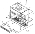
- an apparatus 1 for heating rooms, insertable for example into a fireplace comprising a supporting structure 2 upwardly provided with a connecting element 3 arranged for connecting the apparatus with a flue.
- Containing means 4 for containing particulate solid fuel, for example pellets of wood, and brazier means 5 in which the combustion of said pellets takes place are arranged into said supporting structure 2.
- a grid 6 is positioned below said brazier means 5, arranged for collecting the ash and the possible further products originated from the combustion in order to transfer said ash and possible further products into an underlying collecting drawer 7 from which said ash and possible further products can be periodically removed.
- Transferring means 8 is arranged between the brazier means 5 and the containing means 4, suitable for collecting the solid fuel from the containing means 4 and introducing said solid fuel into the brazier means 5 for feeding the combustion.
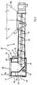
- the transferring means 8 comprises feeding duct means 10 extending between a lower portion 28 of the containing means 4, said lower portion 28 having converging walls inclined downwardly for causing the solid fuel to outflow, and an inlet 18 of the brazier means 5.
- the feeding duct means 10 comprises, at one end thereof, connecting means 12 arranged for connecting the lower portion 28 with the feeding duct means 10 for allowing the solid fuel to pass through said feeding duct means 10.
- Screw conveyor means 13 is arranged internally to said feeding duct means 10, said screw conveyor means being driven by respective driving means 14 firmly coupled to the transferring means 8.
- the transferring means 5 may be easily separated from the brazier means 5 by simply removing the feeding duct means 10 from the brazier means 5, which allows maintaining operations, cleaning operations and/or substitutions of the screw conveyor means 13 and of the respective driving means 14 to be carried out.
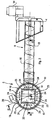
- the brazier means 5 comprises a tubular external body 15 downwardly open and into which a metallic liner.16 is placed, said liner 16 defining a cavity 17 arranged for containing the solid fuel introduced thereinto through the inlet 18.
- the solid fuel pushed by further material transported by the screw conveyor means 13 fills the cavity 17 until it emerges therefrom through a hearth 22 in which the combustion takes place.
- a clearance 34 is defined between the external tubular body 15 and the metallic liner 16.
- the tubular body 15 is provided with a bore 19 through which air blown by a not represented fan is introduced into the clearance 34, through a tube 20, said air being arranged for promoting the combustion.
- the liner 16, near the bore 19, is shaped so as not to prevent air from entering into the tubular body 15.
- the aforesaid fan feeds, in' addition, a further tube 21 connected with the transferring means 8 for mixing air and solid fuel during transferring so obtaining a more efficient combustion in the brazier means 5.
- the air contained in the clearance 34 reaches the hearth 22 by outflowing through a series of bores obtained in the liner 16.
- a first plurality of bores 23 is obtained in the vertical wall 16a of the liner 16, so that the air can pass into the cavity 17 being mixed with the solid fuel before the combustion, whereas a second plurality of bores 24, obtained in the horizontal wall 16b of the liner 16, allows a proper amount of air to be supplied to the hearth 22.
- Rotation driving means 25 is downwardly associated with the brazier means 5; said rotation driving means 25 is arranged for rotating the brazier means 5 by moving the transferring means 8, firmly coupled thereto, from an operative position, in which said transferring means collect solid fuel from the containing means 5 to a rest position in which the transferring means 8, and possibly the containing means 5, may be subjected to maintenance.
- the brazier means 5 may rotate around a vertical axis thereof, according to the direction of the arrow R, through an angular extension of about 90°.
- the rotation driving means 25 comprises sliding surface means 26 perimetrally delimited by guide means 27 of the above mentioned brazier means 5. By acting on the feeding means 8, it is therefore possible to cause the brazier means 5 to slide on the plane sliding means 26, producing such a wide rotation as to allow a user to reach any point of the apparatus requiring maintenance or cleaning.
- the connecting means 12 is shown in the operative position of the transferring means 8. In such position, the connecting means 12 is firmly fixed to the lower portion 28 of the containing means 4.
- the connecting means 12 comprises an end 12a suitable for engaging respective lip means 28a obtained in the portion 28, and a further end 12b provided with a bore 12c through which a screw 29 may pass, said screw 29 being suitable for engaging a relative threaded bore 28c of a supporting element 28b of the portion 28 for assuring, during operating, connection between the transferring means 8 and the containing means 4.
- the transferring means 8 In order to return to the operative position, the transferring means 8 has to be rotated in an opposite direction with respect to the previous direction until the end 12a is inserted into the lip means 28a. Subsequently, the connecting means 12 has to be fixed to the containing means 4 by tightening the screw 29 into the respective threaded bore 28c.
- exhaust means 30 is interposed between the feeding duct means 10 and the brazier means 5, arranged for allowing evacuation of smokes generated during the combustion and present in the cavity 17 due to possible obstructions of the hearth means 22.
- the exhaust means 30 comprises duct means 31 provided with a first end 32 opening into the feeding duct means 10 and a second end 33 opening into the clearance 34. In this manner the smokes possibly present in the feeding duct means 10, instead of directing towards the containing means 4, are conveyed into the clearance 34 and exit from the clearance 34 through the bores 24.
Landscapes
- Engineering & Computer Science (AREA)
- Chemical & Material Sciences (AREA)
- Combustion & Propulsion (AREA)
- Mechanical Engineering (AREA)
- General Engineering & Computer Science (AREA)
- Physics & Mathematics (AREA)
- Thermal Sciences (AREA)
- Solid-Fuel Combustion (AREA)
Applications Claiming Priority (4)
| Application Number | Priority Date | Filing Date | Title |
|---|---|---|---|
| IT2000MO000195 IT1315669B1 (it) | 2000-09-22 | 2000-09-22 | Mezzi per il riscaldamento di ambienti |
| ITMO000195 | 2000-09-22 | ||
| ITMO010041 | 2001-03-08 | ||
| IT2001MO000041A ITMO20010041A1 (it) | 2001-03-08 | 2001-03-08 | Mezzi per il riscaldamento di ambienti |
Publications (2)
| Publication Number | Publication Date |
|---|---|
| EP1191284A2 true EP1191284A2 (de) | 2002-03-27 |
| EP1191284A3 EP1191284A3 (de) | 2002-08-14 |
Family
ID=26332796
Family Applications (1)
| Application Number | Title | Priority Date | Filing Date |
|---|---|---|---|
| EP01122804A Withdrawn EP1191284A3 (de) | 2000-09-22 | 2001-09-21 | Vorrichtung zur Raumheizung |
Country Status (1)
| Country | Link |
|---|---|
| EP (1) | EP1191284A3 (de) |
Family Cites Families (5)
| Publication number | Priority date | Publication date | Assignee | Title |
|---|---|---|---|---|
| US2412193A (en) * | 1946-12-10 | Fuel feeding apparatus | ||
| US2191219A (en) * | 1935-04-24 | 1940-02-20 | Henry M Brooks | Stoker |
| US2384762A (en) * | 1943-05-29 | 1945-09-11 | Gen Refractories Co | Mechanical stoker for kilns and their mountings |
| US4323017A (en) * | 1980-04-16 | 1982-04-06 | Harris Loren A | Burner apparatus |
| DE4310681C1 (de) * | 1993-04-01 | 1994-03-24 | Deutsche Aerospace | Anlage zur Entsorgung von Explosivstoffen |
-
2001
- 2001-09-21 EP EP01122804A patent/EP1191284A3/de not_active Withdrawn
Also Published As
| Publication number | Publication date |
|---|---|
| EP1191284A3 (de) | 2002-08-14 |
Similar Documents
| Publication | Publication Date | Title |
|---|---|---|
| US7318431B1 (en) | Biomass fuel burning stove and method | |
| EP0287534B1 (de) | Einrichtung zur Pyrolyse von Reifenkarkassen | |
| CA2437509A1 (en) | Method and apparatus for drying and incineration of sewage sludge | |
| IE20090766A1 (en) | An energy conversion system | |
| US20030196577A1 (en) | Two-stage wet waste gasifier and burner | |
| US5070798A (en) | Pellet burner appliances and burners therefor | |
| US4574712A (en) | Wood chip burning stoker type furnace | |
| EP0985883B1 (de) | Heizvorrichtung | |
| US4300456A (en) | Auger-fed sawdust burner with revolving hopper | |
| WO2017048314A1 (en) | Improved pellet stove | |
| US4840130A (en) | Waste disposal system | |
| EP1191284A2 (de) | Vorrichtung zur Raumheizung | |
| US5582117A (en) | Firepot with ash-dumping floor | |
| US4723494A (en) | Incinerator discharge systems | |
| KR101757737B1 (ko) | 고체연료용 열풍기 | |
| US20080156312A1 (en) | Pellet stove | |
| JP4044431B2 (ja) | ペレット燃料燃焼装置 | |
| EP1843091B1 (de) | Festbrennstoffbrenner und Verfahren zum Reinigen der Brennkammer | |
| JP2007132588A (ja) | 木質系材料の燃焼室構造 | |
| WO1998037363A1 (en) | Combustion device for solid fuel | |
| WO2003012007A1 (en) | Apparatus for the pyrolysis of waste material | |
| JP2004191014A (ja) | ペレット燃料燃焼装置 | |
| US256522A (en) | Automatic furnace-feeder | |
| JPS6026936B2 (ja) | 木材チツプ燃焼装置 | |
| GB2093961A (en) | Solid fuel burners |
Legal Events
| Date | Code | Title | Description |
|---|---|---|---|
| PUAI | Public reference made under article 153(3) epc to a published international application that has entered the european phase |
Free format text: ORIGINAL CODE: 0009012 |
|
| AK | Designated contracting states |
Kind code of ref document: A2 Designated state(s): AT BE CH CY DE DK ES FI FR GB GR IE IT LI LU MC NL PT SE TR |
|
| AX | Request for extension of the european patent |
Free format text: AL;LT;LV;MK;RO;SI |
|
| PUAL | Search report despatched |
Free format text: ORIGINAL CODE: 0009013 |
|
| AK | Designated contracting states |
Kind code of ref document: A3 Designated state(s): AT BE CH CY DE DK ES FI FR GB GR IE IT LI LU MC NL PT SE TR |
|
| AX | Request for extension of the european patent |
Free format text: AL;LT;LV;MK;RO;SI |
|
| AKX | Designation fees paid | ||
| REG | Reference to a national code |
Ref country code: DE Ref legal event code: 8566 |
|
| STAA | Information on the status of an ep patent application or granted ep patent |
Free format text: STATUS: THE APPLICATION IS DEEMED TO BE WITHDRAWN |
|
| 18D | Application deemed to be withdrawn |
Effective date: 20030215 |