EP1191257A2 - Vehicle transmission - Google Patents
Vehicle transmission Download PDFInfo
- Publication number
- EP1191257A2 EP1191257A2 EP01121113A EP01121113A EP1191257A2 EP 1191257 A2 EP1191257 A2 EP 1191257A2 EP 01121113 A EP01121113 A EP 01121113A EP 01121113 A EP01121113 A EP 01121113A EP 1191257 A2 EP1191257 A2 EP 1191257A2
- Authority
- EP
- European Patent Office
- Prior art keywords
- gear
- shaft
- sub
- speed
- clutch
- Prior art date
- Legal status (The legal status is an assumption and is not a legal conclusion. Google has not performed a legal analysis and makes no representation as to the accuracy of the status listed.)
- Granted
Links
Images


Classifications
-
- F—MECHANICAL ENGINEERING; LIGHTING; HEATING; WEAPONS; BLASTING
- F16—ENGINEERING ELEMENTS AND UNITS; GENERAL MEASURES FOR PRODUCING AND MAINTAINING EFFECTIVE FUNCTIONING OF MACHINES OR INSTALLATIONS; THERMAL INSULATION IN GENERAL
- F16H—GEARING
- F16H57/00—General details of gearing
- F16H57/02—Gearboxes; Mounting gearing therein
- F16H57/021—Shaft support structures, e.g. partition walls, bearing eyes, casing walls or covers with bearings
-
- F—MECHANICAL ENGINEERING; LIGHTING; HEATING; WEAPONS; BLASTING
- F16—ENGINEERING ELEMENTS AND UNITS; GENERAL MEASURES FOR PRODUCING AND MAINTAINING EFFECTIVE FUNCTIONING OF MACHINES OR INSTALLATIONS; THERMAL INSULATION IN GENERAL
- F16H—GEARING
- F16H3/00—Toothed gearings for conveying rotary motion with variable gear ratio or for reversing rotary motion
- F16H3/02—Toothed gearings for conveying rotary motion with variable gear ratio or for reversing rotary motion without gears having orbital motion
- F16H3/08—Toothed gearings for conveying rotary motion with variable gear ratio or for reversing rotary motion without gears having orbital motion exclusively or essentially with continuously meshing gears, that can be disengaged from their shafts
- F16H3/087—Toothed gearings for conveying rotary motion with variable gear ratio or for reversing rotary motion without gears having orbital motion exclusively or essentially with continuously meshing gears, that can be disengaged from their shafts characterised by the disposition of the gears
- F16H3/093—Toothed gearings for conveying rotary motion with variable gear ratio or for reversing rotary motion without gears having orbital motion exclusively or essentially with continuously meshing gears, that can be disengaged from their shafts characterised by the disposition of the gears with two or more countershafts
-
- F—MECHANICAL ENGINEERING; LIGHTING; HEATING; WEAPONS; BLASTING
- F16—ENGINEERING ELEMENTS AND UNITS; GENERAL MEASURES FOR PRODUCING AND MAINTAINING EFFECTIVE FUNCTIONING OF MACHINES OR INSTALLATIONS; THERMAL INSULATION IN GENERAL
- F16H—GEARING
- F16H3/00—Toothed gearings for conveying rotary motion with variable gear ratio or for reversing rotary motion
- F16H3/02—Toothed gearings for conveying rotary motion with variable gear ratio or for reversing rotary motion without gears having orbital motion
- F16H3/08—Toothed gearings for conveying rotary motion with variable gear ratio or for reversing rotary motion without gears having orbital motion exclusively or essentially with continuously meshing gears, that can be disengaged from their shafts
- F16H3/087—Toothed gearings for conveying rotary motion with variable gear ratio or for reversing rotary motion without gears having orbital motion exclusively or essentially with continuously meshing gears, that can be disengaged from their shafts characterised by the disposition of the gears
- F16H3/093—Toothed gearings for conveying rotary motion with variable gear ratio or for reversing rotary motion without gears having orbital motion exclusively or essentially with continuously meshing gears, that can be disengaged from their shafts characterised by the disposition of the gears with two or more countershafts
- F16H2003/0938—Toothed gearings for conveying rotary motion with variable gear ratio or for reversing rotary motion without gears having orbital motion exclusively or essentially with continuously meshing gears, that can be disengaged from their shafts characterised by the disposition of the gears with two or more countershafts with multiple gears on the input shaft directly meshing with respective gears on the output shaft
-
- F—MECHANICAL ENGINEERING; LIGHTING; HEATING; WEAPONS; BLASTING
- F16—ENGINEERING ELEMENTS AND UNITS; GENERAL MEASURES FOR PRODUCING AND MAINTAINING EFFECTIVE FUNCTIONING OF MACHINES OR INSTALLATIONS; THERMAL INSULATION IN GENERAL
- F16H—GEARING
- F16H2200/00—Transmissions for multiple ratios
- F16H2200/003—Transmissions for multiple ratios characterised by the number of forward speeds
- F16H2200/0047—Transmissions for multiple ratios characterised by the number of forward speeds the gear ratios comprising five forward speeds
-
- Y—GENERAL TAGGING OF NEW TECHNOLOGICAL DEVELOPMENTS; GENERAL TAGGING OF CROSS-SECTIONAL TECHNOLOGIES SPANNING OVER SEVERAL SECTIONS OF THE IPC; TECHNICAL SUBJECTS COVERED BY FORMER USPC CROSS-REFERENCE ART COLLECTIONS [XRACs] AND DIGESTS
- Y10—TECHNICAL SUBJECTS COVERED BY FORMER USPC
- Y10T—TECHNICAL SUBJECTS COVERED BY FORMER US CLASSIFICATION
- Y10T74/00—Machine element or mechanism
- Y10T74/19—Gearing
- Y10T74/19219—Interchangeably locked
- Y10T74/19233—Plurality of counter shafts
-
- Y—GENERAL TAGGING OF NEW TECHNOLOGICAL DEVELOPMENTS; GENERAL TAGGING OF CROSS-SECTIONAL TECHNOLOGIES SPANNING OVER SEVERAL SECTIONS OF THE IPC; TECHNICAL SUBJECTS COVERED BY FORMER USPC CROSS-REFERENCE ART COLLECTIONS [XRACs] AND DIGESTS
- Y10—TECHNICAL SUBJECTS COVERED BY FORMER USPC
- Y10T—TECHNICAL SUBJECTS COVERED BY FORMER US CLASSIFICATION
- Y10T74/00—Machine element or mechanism
- Y10T74/19—Gearing
- Y10T74/19628—Pressure distributing
-
- Y—GENERAL TAGGING OF NEW TECHNOLOGICAL DEVELOPMENTS; GENERAL TAGGING OF CROSS-SECTIONAL TECHNOLOGIES SPANNING OVER SEVERAL SECTIONS OF THE IPC; TECHNICAL SUBJECTS COVERED BY FORMER USPC CROSS-REFERENCE ART COLLECTIONS [XRACs] AND DIGESTS
- Y10—TECHNICAL SUBJECTS COVERED BY FORMER USPC
- Y10T—TECHNICAL SUBJECTS COVERED BY FORMER US CLASSIFICATION
- Y10T74/00—Machine element or mechanism
- Y10T74/21—Elements
- Y10T74/2186—Gear casings
Definitions
- the present invention relates to a vehicle transmission in which a group of parts including at least an input gear and an output gear are stacked and supported on a shaft supported in a casing via at least a pair of bearings, and a torque that has been input to the input gear is output from the output gear.
- Assembled around a main shaft or a counter shaft of an automatic transmission in order to establish each of the gear shift stages are parts including, for example, a gear, a clutch outer and a clutch inner of a hydraulic clutch for engaging the gear with the shaft, and bearings for supporting the shaft in a casing.
- Such a plurality of parts are stacked on the shaft, the parts are retained at one end by a step formed on the shaft, and are retained at the other end by means of a nut screwed into the outer circumference of the shaft, as disclosed in Japanese Patent Application Laid-open No. 11-82646.
- a helical gear is characterized by receiving a thrust force accompanying the transmission of a torque.
- thrust forces that are generated in opposite directions, not only is it necessary to secure the helical gears to the shaft by a large nut or bolt that can withstand the thrust forces, but it is also necessary to employ means for preventing the nut or bolt from loosening.
- the present invention has been carried out in view of the above-mentioned circumstances and it is an object of the present invention to eliminate the necessity of fixing helical gears supported on a shaft of a transmission by a nut or a bolt in the axial direction, thus saving space and reducing the number of parts.
- the present invention is directed to a vehicle transmission in which a group of parts including at least an input gear and an output gear are stacked and supported on a shaft supported in casings via at least one pair of bearings and a torque that has been input to the input gear is output from the output gear, wherein the input gear and the output gear are helical gears, thrust forces acting on the input gear and the output gear are generated in opposite directions, the thrust force acting on one gear is borne by the casing via a shaft end of the shaft, and the thrust force acting on another gear is borne by the casing via a side of the gear.
- the input gear and the output gear supported on the shaft are helical gears, and when they experience the thrust forces in opposite directions, the thrust force acting on the one gear is borne by the casing via the shaft end, and the thrust force acting on the other gear is borne by the casing via the side of the gear. It is therefore unnecessary to fix the two gears to the shaft by a bolt or a nut and to employ means for preventing the bolt or nut from loosening. Space can thus be saved and the number of parts can be reduced.
- the present invention is also directed to a vehicle transmission wherein a retaining part provided integrally on the shaft restricts movement of the one gear in the direction in which the one gear departs from the other gear, and a retaining means detachably provided on the shaft restricts movement of the other gear in the direction in which the other gear departs from the one gear.
- the retaining part provided integrally on the shaft restricts movement of the one gear in the direction in which the one gear departs from the other gear, the thrust force acting on the one gear can be transmitted to the shaft and borne by the casing.
- the retaining means detachably provided on the shaft restricts movement of the other gear in the direction in which the other gear departs from the one gear, it is possible to provisionally assemble the other gear on the shaft while preventing the other gear and the group of parts from dropping off the shaft, thus enhancing ease of assembly.
- a torque converter case 11 and a transmission case 12 in the embodiment below correspond to the casings of the present invention
- a sub-shaft drive fourth gear 34 in the embodiment corresponds to the input gear or the one gear of the present invention
- a second sub third speed gear 46 in the embodiment corresponds to the output gear or the other gear of the present invention
- a ball bearing 20, a roller bearing 21 and a thrust bearing 69 in the embodiment correspond to the bearings of the present invention
- a second sub-shaft Ss2 in the embodiment corresponds to the shaft of the present invention
- an annular projection 61 in the embodiment corresponds to the retaining part of the present invention
- a cotter 67 in the embodiment corresponds to the retaining means of the present invention.
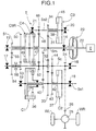
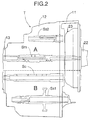
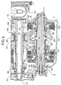
- FIGS. 1 to 6 illustrate one embodiment of the present invention, where
- the outer periphery of a four parallel shaft type automatic transmission T connected to the left-hand side face of an engine E comprises a torque converter case 11, a transmission case 12 and a case cover 13.
- the torque converter case 11 and the transmission case 12 support a main shaft Sm via ball bearings 14 and 15, a counter shaft Sc via a roller bearing 16 and a ball bearing 17, a first sub-shaft Ss1 via ball bearings 18 and 19, and a second sub-shaft Ss2 via a ball bearing 20 and a roller bearing 21.
- the main shaft Sm is connected to a crankshaft 22 of the engine E via a torque converter 23.
- a final drive gear 24 integral with the counter shaft Sc is meshed with a final driven gear 26 fixed on the outer periphery of a differential gear box 25 so as to drive right and left driven wheels WR and WL.
- a first speed clutch C1 and a second speed clutch C2 are provided on the first sub-shaft Ss1
- a third speed clutch C3 is provided on the second sub-shaft Ss2
- a fourth speed clutch C4 and a fifth speed - reverse clutch C5R are provided on the main shaft Sm.
- a sub-shaft drive first gear 31 integral with the main shaft Sm is meshed with a sub-shaft drive second gear 32 supported on the counter shaft Sc in a relatively rotatable manner
- this sub-shaft drive second gear 32 is meshed with a sub-shaft drive third gear 33 integral with the first sub-shaft Ss1
- the above-mentioned sub-shaft drive first gear 31 is meshed with a sub-shaft drive fourth gear 34 supported on the second sub-shaft Ss2 in a relatively rotatable manner.
- the first sub-shaft Ss1 having the integral sub-shaft drive third gear 33 meshed with the above-mentioned sub-shaft drive second gear 32 always rotates and the clutch outers 36 and 37 of the first speed clutch C1 and the second speed clutch C2 provided on this first sub-shaft Ss1 also always rotate.
- the sub-shaft drive fourth gear 34 supported on the second sub-shaft Ss2 in a relatively rotatable manner and meshed with the sub-shaft drive first gear 31, and a clutch inner 38 of the third speed clutch C3 connected integrally to this sub-shaft drive fourth gear 34 also always rotate.
- a first sub first speed gear 40 integral with a clutch inner 39 of the first speed clutch C1 provided on the first sub-shaft Ss1 is meshed with a counter first speed gear 41 integral with the counter shaft Sc.
- a first sub second speed gear 43 integral with a clutch inner 42 of the second speed clutch C2 provided on the first sub-shaft Ss1 is meshed with a counter second speed gear 44 integral with the counter shaft Sc.
- a clutch outer 45 of the third speed clutch C3 and a second sub third speed gear 46 are integrally provided on the second sub-shaft Ss2.
- a main third speed - fourth speed gear 48 integral with a clutch inner 47 of the fourth speed clutch C4 provided on the main shaft Sm is meshed with the above-mentioned second sub third speed gear 46 integral with the second sub-shaft Ss2.
- a main fifth speed gear 50 and a main reverse gear 51 are provided integrally with a clutch inner 49 of the fifth speed - reverse clutch C5R provided on the main shaft Sm.
- a counter third speed - fourth speed gear 52 integral with the counter shaft Sc is meshed with the above-mentioned main third speed - fourth speed gear 48.
- a counter fifth speed gear 53 and a counter reverse gear 54 are supported on the counter shaft Sc in a relatively rotatable manner, the counter fifth speed gear 53 is meshed with the above-mentioned main fifth speed gear 50, and the counter reverse gear 54 is meshed with the above-mentioned main reverse gear 51 via a reverse idle gear 55 (see FIG. 1).
- the counter fifth speed gear 53 and the counter reverse gear 54 on the counter shaft Sc can be selectively coupled to the counter shaft Sc by means of a chamfer 56.
- the rotation of the main shaft Sm is transmitted to the driven wheels WR and WL through the sub-shaft drive first gear 31, then the sub-shaft drive second gear 32, the sub-shaft drive third gear 33, the first sub-shaft Ss1, the clutch outer 36 and the clutch inner 39 of the first speed clutch C1, the first sub first speed gear 40, the counter first speed gear 41, the counter shaft Sc, the final drive gear 24, the final driven gear 26 and the differential gear box 25.
- annular projection 61 is formed on the outer periphery of the second sub-shaft Ss2 at its right end, an inner race 20a of the ball bearing 20 is in contact with the right-hand side face of the annular projection 61, and an outer race 20b is in contact with a step 11a of the torque converter case 11.
- a thrust washer 68 for adjusting clearance
- a thrust bearing 69 and a thrust washer 70 Since there is a small gap between the cotter key 67 and the second sub third speed gear 46, the second sub third speed gear 46 can slide relative to the second sub-shaft Ss2 within the compass of the above-mentioned gap.
- the feed pipe cap 71 is prevented from rotating and falling out by a stay 76 fixed to the transmission case 12 by means of a bolt 75.
- An end of a feed pipe 77 is fixed to the feed pipe cap 71 and the other end thereof extends within an oil passage 78 formed in the center of the second sub-shaft Ss2 so that an operating fluid can be supplied to a clutch oil chamber 79 of the third speed clutch C3.
- Variations in the thickness of the boss 45a of the clutch outer 45, the thrust washer 64, the thrust bearing 65, the sub-shaft drive fourth gear 34, the thrust bearing 66, the second sub third speed gear 46, the thrust bearing 69 and the thrust washer 70 can be absorbed by selecting and mounting the thrust washer 68 having an appropriate thickness for adjusting the clearance.
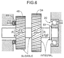
- each of the gears of the automatic transmission T including the sub-shaft drive fourth gear 34 and the second sub third speed gear 46 is a helical gear which causes only a small engagement noise, thrust forces act on the engaged parts accompanying the transmission of a torque.
- the sub-shaft drive fourth gear 34 and the second sub third speed gear 46 rotate in the direction of arrows R.
- the sub-shaft drive fourth gear 34 and the teeth of the second sub third speed gear 46 which are helical gears, are both inclined downward and to the left in the figure
- the sub-shaft drive fourth gear 34 driven by the sub-shaft drive first gear 31 experiences a thrust force F1 in the rightward direction in the figure
- the second sub third speed gear 46 driving the main third speed - fourth speed gear 48 experiences a thrust force F2 in the leftward direction in the figure.
- the two thrust forces F1 and F2 which are generated in opposite directions, have an identical absolute value.
- the thrust force F1 pushing the sub-shaft drive fourth gear 34 rightward acts on the annular projection 61 via the thrust bearing 65, the thrust washer 64, the boss 45a of the clutch outer 45, the clip 63 and the parking gear 62 so pushing the second sub-shaft Ss2 rightward.
- the thrust force F1 pushing the second sub-shaft Ss2 rightward is supported by the torque converter case 11 via the ball bearing 20 provided on the shaft end of the second sub-shaft Ss2.
- the cotter key 67 is separated from the second sub third speed gear 46 by a small gap and does not contribute to bearing the thrust forces F1 and F2.
- the function of the cotter key 67 is to enhance the ease of assembly when preliminarily assembling the parking gear 62, the boss 45a of the clutch outer 45, the thrust washer 64, the thrust bearing 65, the sub-shaft drive fourth gear 34, the thrust bearing 66 and the second sub third speed gear 46 around the second sub-shaft Ss2 while preventing these members from dropping off the second sub-shaft Ss2.
- the embodiment illustrates an automatic transmission T, but the present invention can be applied to a manual transmission. It is also possible to employ another retaining member such as a circlip instead of the cotter key 67.
- a transmission for a vehicle having a sub shaft supported in casings via bearings, and an input gear, an output gear, and a boss of a clutch outer, etc. stacked on the sub shaft and retained by a cotter key.
- the input gear and the output gear are helical gears, and thrust forces acting on the two gears are generated in opposite directions.
- a rightward thrust force acting on the input gear is borne by the casing via an annular projection, the sub shaft and the bearing, and a leftward force acting on the output gear, which is separated from the cotter key by a gap, is borne by the casing via the bearing provided on the side face of the output gear.
Landscapes
- Engineering & Computer Science (AREA)
- General Engineering & Computer Science (AREA)
- Mechanical Engineering (AREA)
- Structure Of Transmissions (AREA)
- Gear Transmission (AREA)
- General Details Of Gearings (AREA)
Abstract
Description
Claims (2)
- A vehicle transmission, comprising:a group of parts including at least an input gear and an output gear which are stacked and supported on a shaft supported in casings via at least one pair of bearings, a torque that has been input to the input gear being output from the output gear, wherein:the input gear and the output gear are helical gears,first and second thrust forces acting on the input gear and the output gear, respectively, are generated in opposite directions,one of said first thrust force and said second thrust force is borne by the casing via a shaft end of the shaft, andthe other of said first thrust force and said second thrust force is borne by the casing via a side of the output gear.
- The vehicle transmission according to Claim 1, further comprising a retaining part provided integrally on the shaft for restricting movement of one of the input gear and the output gear in the direction in which the one departs from the other, and a retaining means detachably provided on the shaft for restricting movement of the other of the input gear and the output gear in the direction in which the other departs from the one.
Applications Claiming Priority (2)
| Application Number | Priority Date | Filing Date | Title |
|---|---|---|---|
| JP2000273889A JP4346059B2 (en) | 2000-09-08 | 2000-09-08 | Vehicle transmission |
| JP2000273889 | 2000-09-08 |
Publications (3)
| Publication Number | Publication Date |
|---|---|
| EP1191257A2 true EP1191257A2 (en) | 2002-03-27 |
| EP1191257A3 EP1191257A3 (en) | 2002-04-03 |
| EP1191257B1 EP1191257B1 (en) | 2003-11-12 |
Family
ID=18759748
Family Applications (1)
| Application Number | Title | Priority Date | Filing Date |
|---|---|---|---|
| EP01121113A Expired - Lifetime EP1191257B1 (en) | 2000-09-08 | 2001-09-03 | Vehicle transmission |
Country Status (6)
| Country | Link |
|---|---|
| US (1) | US6802230B2 (en) |
| EP (1) | EP1191257B1 (en) |
| JP (1) | JP4346059B2 (en) |
| CA (1) | CA2356772C (en) |
| DE (1) | DE60101191T2 (en) |
| MX (1) | MXPA01009066A (en) |
Families Citing this family (8)
| Publication number | Priority date | Publication date | Assignee | Title |
|---|---|---|---|---|
| KR100598874B1 (en) * | 2003-11-17 | 2006-07-10 | 현대자동차주식회사 | Automatic transmission |
| DE102008018545A1 (en) * | 2008-04-12 | 2009-10-15 | Schaeffler Kg | Shaft with roller bearings |
| EP2345829B1 (en) * | 2008-11-14 | 2013-01-09 | Honda Motor Co., Ltd. | Transmission |
| US9341238B2 (en) | 2012-06-15 | 2016-05-17 | Gkn Driveline North America, Inc. | Power transfer unit straddle mount ring gear disconnect |
| WO2014000751A1 (en) * | 2012-06-25 | 2014-01-03 | Volvo Lastvagnar Ab | Gear arrangement and dual-clutch transmission provided therewith |
| JP6002709B2 (en) * | 2014-03-28 | 2016-10-05 | 本田技研工業株式会社 | Internal combustion engine transmission |
| JP6453700B2 (en) * | 2015-04-20 | 2019-01-16 | Ntn株式会社 | Two-motor vehicle drive device |
| DE202020107259U1 (en) * | 2020-12-15 | 2022-03-17 | Dana Belgium N.V. | Compact powertrain |
Family Cites Families (13)
| Publication number | Priority date | Publication date | Assignee | Title |
|---|---|---|---|---|
| US2057073A (en) * | 1935-01-10 | 1936-10-13 | White Motor Co | Change speed mechanism |
| US2774451A (en) * | 1949-10-31 | 1956-12-18 | Daimler Benz Ag | Shiftable clutch in change speed transmission |
| US3563105A (en) * | 1968-10-12 | 1971-02-16 | Istituto Per Le Ricerche Di Te | Toothed meshing transmission mechanisms |
| US3772934A (en) * | 1971-11-15 | 1973-11-20 | R Warren | Floating helical gear |
| US3885446A (en) * | 1972-04-29 | 1975-05-27 | Eric Alexander Pengilly | Gearing-torque division |
| US4025136A (en) * | 1975-11-03 | 1977-05-24 | Allis-Chalmers Corporation | Multiple bearing adjusting device |
| DE3018610C2 (en) * | 1980-05-13 | 1982-08-19 | Mannesmann AG, 4000 Düsseldorf | Multi-way gearboxes with load balancing, especially for ships |
| US4385846A (en) * | 1981-03-11 | 1983-05-31 | General Motors Corporation | Axial-bearing arrangement on shafts, in particular in speed-change gears of motor vehicles |
| EP0172286B1 (en) * | 1984-08-22 | 1988-08-10 | Toyota Jidosha Kabushiki Kaisha | Transmission for use in motor vehicle |
| JPH0821489A (en) * | 1994-07-08 | 1996-01-23 | Fanuc Ltd | Gear device |
| JP3533898B2 (en) * | 1997-09-01 | 2004-05-31 | アイシン・エィ・ダブリュ株式会社 | Automatic transmission with spline coupling structure |
| JP4056614B2 (en) * | 1998-03-20 | 2008-03-05 | 住友重機械工業株式会社 | Parallel shaft gear reducer |
| JP3856085B2 (en) * | 2000-08-01 | 2006-12-13 | 日産自動車株式会社 | Power transmission device for vehicle |
-
2000
- 2000-09-08 JP JP2000273889A patent/JP4346059B2/en not_active Expired - Fee Related
-
2001
- 2001-08-31 CA CA002356772A patent/CA2356772C/en not_active Expired - Fee Related
- 2001-09-03 EP EP01121113A patent/EP1191257B1/en not_active Expired - Lifetime
- 2001-09-03 DE DE60101191T patent/DE60101191T2/en not_active Expired - Lifetime
- 2001-09-06 US US09/946,963 patent/US6802230B2/en not_active Expired - Lifetime
- 2001-09-07 MX MXPA01009066A patent/MXPA01009066A/en active IP Right Grant
Also Published As
| Publication number | Publication date |
|---|---|
| EP1191257B1 (en) | 2003-11-12 |
| EP1191257A3 (en) | 2002-04-03 |
| JP2002081512A (en) | 2002-03-22 |
| CA2356772C (en) | 2005-02-22 |
| JP4346059B2 (en) | 2009-10-14 |
| DE60101191T2 (en) | 2004-04-22 |
| CA2356772A1 (en) | 2002-03-08 |
| DE60101191D1 (en) | 2003-12-18 |
| MXPA01009066A (en) | 2005-06-30 |
| US20020033062A1 (en) | 2002-03-21 |
| US6802230B2 (en) | 2004-10-12 |
Similar Documents
| Publication | Publication Date | Title |
|---|---|---|
| EP1245863B1 (en) | A motor-vehicle gearbox | |
| US6758786B2 (en) | Integrated assembly comprising a hydraulic clutch and a planetary gear train, in particular for automatic transmission particularly of vehicles, and automatic transmission comprising same | |
| US7267022B2 (en) | Multistep transmission of a layshaft type | |
| EP1191257B1 (en) | Vehicle transmission | |
| US6592489B2 (en) | Transmission equipped with planetary gear mechanism and planetary gear mechanism | |
| JPH0242240A (en) | Automatic transmission | |
| JP5023030B2 (en) | Friction clutch fastening mechanism and differential device including the mechanism | |
| JPWO2014129658A1 (en) | Power transmission device | |
| US5584775A (en) | Automatic transmission for transverse engine vehicle | |
| US20020026840A1 (en) | Three parallel shaft type automatic transmission | |
| EP1186803B1 (en) | Bearing support for counter shaft in a vehicle transmission | |
| US4966264A (en) | Thrust washer mounting apparatus | |
| US5029688A (en) | Lubrication device for a one-way clutch in an automatic transmission | |
| US5590571A (en) | Structure for mounting an output gear and bearing to a transmission | |
| US12085132B2 (en) | Modified vehicle transmission | |
| JPH10169728A (en) | Double pinion type planetary gear unit | |
| JP3001486B2 (en) | Gear type transmission | |
| US8161836B2 (en) | Multi-step transmission | |
| JP3849893B2 (en) | Gear transmission structure | |
| US7837590B2 (en) | Transmission assembly | |
| JPH0796897B2 (en) | Counter gear support device for automatic transmission | |
| EP1818570B1 (en) | Arrangement of an idler gear in a gear transmission | |
| KR100423543B1 (en) | Mounting structure for bearing of manual transmission | |
| EP1186807B1 (en) | Choke valve for automatic transmission | |
| JPH1163123A (en) | Automatic transmission |
Legal Events
| Date | Code | Title | Description |
|---|---|---|---|
| PUAI | Public reference made under article 153(3) epc to a published international application that has entered the european phase |
Free format text: ORIGINAL CODE: 0009012 |
|
| PUAL | Search report despatched |
Free format text: ORIGINAL CODE: 0009013 |
|
| AK | Designated contracting states |
Kind code of ref document: A2 Designated state(s): DE GB Kind code of ref document: A2 Designated state(s): AT BE CH CY DE DK ES FI FR GB GR IE IT LI LU MC NL PT SE TR |
|
| AX | Request for extension of the european patent |
Free format text: AL;LT;LV;MK;RO;SI |
|
| AK | Designated contracting states |
Kind code of ref document: A3 Designated state(s): AT BE CH CY DE DK ES FI FR GB GR IE IT LI LU MC NL PT SE TR |
|
| AX | Request for extension of the european patent |
Free format text: AL;LT;LV;MK;RO;SI |
|
| 17P | Request for examination filed |
Effective date: 20020925 |
|
| AKX | Designation fees paid |
Free format text: DE GB |
|
| GRAH | Despatch of communication of intention to grant a patent |
Free format text: ORIGINAL CODE: EPIDOS IGRA |
|
| GRAS | Grant fee paid |
Free format text: ORIGINAL CODE: EPIDOSNIGR3 |
|
| GRAA | (expected) grant |
Free format text: ORIGINAL CODE: 0009210 |
|
| AK | Designated contracting states |
Kind code of ref document: B1 Designated state(s): DE GB |
|
| REG | Reference to a national code |
Ref country code: GB Ref legal event code: FG4D |
|
| REF | Corresponds to: |
Ref document number: 60101191 Country of ref document: DE Date of ref document: 20031218 Kind code of ref document: P |
|
| REG | Reference to a national code |
Ref country code: IE Ref legal event code: FG4D |
|
| PLBE | No opposition filed within time limit |
Free format text: ORIGINAL CODE: 0009261 |
|
| STAA | Information on the status of an ep patent application or granted ep patent |
Free format text: STATUS: NO OPPOSITION FILED WITHIN TIME LIMIT |
|
| 26N | No opposition filed |
Effective date: 20040813 |
|
| REG | Reference to a national code |
Ref country code: IE Ref legal event code: MM4A |
|
| REG | Reference to a national code |
Ref country code: DE Ref legal event code: R084 Ref document number: 60101191 Country of ref document: DE |
|
| REG | Reference to a national code |
Ref country code: GB Ref legal event code: 746 Effective date: 20150507 |
|
| REG | Reference to a national code |
Ref country code: DE Ref legal event code: R084 Ref document number: 60101191 Country of ref document: DE Effective date: 20150505 |
|
| PGFP | Annual fee paid to national office [announced via postgrant information from national office to epo] |
Ref country code: DE Payment date: 20150825 Year of fee payment: 15 Ref country code: GB Payment date: 20150902 Year of fee payment: 15 |
|
| REG | Reference to a national code |
Ref country code: DE Ref legal event code: R119 Ref document number: 60101191 Country of ref document: DE |
|
| GBPC | Gb: european patent ceased through non-payment of renewal fee |
Effective date: 20160903 |
|
| PG25 | Lapsed in a contracting state [announced via postgrant information from national office to epo] |
Ref country code: DE Free format text: LAPSE BECAUSE OF NON-PAYMENT OF DUE FEES Effective date: 20170401 Ref country code: GB Free format text: LAPSE BECAUSE OF NON-PAYMENT OF DUE FEES Effective date: 20160903 |