EP1191249A2 - Reduction of coil spring load height variability - Google Patents
Reduction of coil spring load height variability Download PDFInfo
- Publication number
- EP1191249A2 EP1191249A2 EP01307798A EP01307798A EP1191249A2 EP 1191249 A2 EP1191249 A2 EP 1191249A2 EP 01307798 A EP01307798 A EP 01307798A EP 01307798 A EP01307798 A EP 01307798A EP 1191249 A2 EP1191249 A2 EP 1191249A2
- Authority
- EP
- European Patent Office
- Prior art keywords
- spring
- height
- isolator
- springs
- load
- Prior art date
- Legal status (The legal status is an assumption and is not a legal conclusion. Google has not performed a legal analysis and makes no representation as to the accuracy of the status listed.)
- Granted
Links
Images


Classifications
-
- F—MECHANICAL ENGINEERING; LIGHTING; HEATING; WEAPONS; BLASTING
- F16—ENGINEERING ELEMENTS AND UNITS; GENERAL MEASURES FOR PRODUCING AND MAINTAINING EFFECTIVE FUNCTIONING OF MACHINES OR INSTALLATIONS; THERMAL INSULATION IN GENERAL
- F16F—SPRINGS; SHOCK-ABSORBERS; MEANS FOR DAMPING VIBRATION
- F16F3/00—Spring units consisting of several springs, e.g. for obtaining a desired spring characteristic
- F16F3/08—Spring units consisting of several springs, e.g. for obtaining a desired spring characteristic with springs made of a material having high internal friction, e.g. rubber
- F16F3/10—Spring units consisting of several springs, e.g. for obtaining a desired spring characteristic with springs made of a material having high internal friction, e.g. rubber combined with springs made of steel or other material having low internal friction
- F16F3/12—Spring units consisting of several springs, e.g. for obtaining a desired spring characteristic with springs made of a material having high internal friction, e.g. rubber combined with springs made of steel or other material having low internal friction the steel spring being in contact with the rubber spring
-
- B—PERFORMING OPERATIONS; TRANSPORTING
- B60—VEHICLES IN GENERAL
- B60G—VEHICLE SUSPENSION ARRANGEMENTS
- B60G11/00—Resilient suspensions characterised by arrangement, location or kind of springs
- B60G11/32—Resilient suspensions characterised by arrangement, location or kind of springs having springs of different kinds
- B60G11/48—Resilient suspensions characterised by arrangement, location or kind of springs having springs of different kinds not including leaf springs
- B60G11/52—Resilient suspensions characterised by arrangement, location or kind of springs having springs of different kinds not including leaf springs having helical, spiral or coil springs, and also rubber springs
- B60G11/54—Resilient suspensions characterised by arrangement, location or kind of springs having springs of different kinds not including leaf springs having helical, spiral or coil springs, and also rubber springs with rubber springs arranged within helical, spiral or coil springs
-
- F—MECHANICAL ENGINEERING; LIGHTING; HEATING; WEAPONS; BLASTING
- F16—ENGINEERING ELEMENTS AND UNITS; GENERAL MEASURES FOR PRODUCING AND MAINTAINING EFFECTIVE FUNCTIONING OF MACHINES OR INSTALLATIONS; THERMAL INSULATION IN GENERAL
- F16F—SPRINGS; SHOCK-ABSORBERS; MEANS FOR DAMPING VIBRATION
- F16F1/00—Springs
- F16F1/02—Springs made of steel or other material having low internal friction; Wound, torsion, leaf, cup, ring or the like springs, the material of the spring not being relevant
- F16F1/04—Wound springs
- F16F1/12—Attachments or mountings
- F16F1/126—Attachments or mountings comprising an element between the end coil of the spring and the support proper, e.g. an elastomeric annulus
-
- B—PERFORMING OPERATIONS; TRANSPORTING
- B60—VEHICLES IN GENERAL
- B60G—VEHICLE SUSPENSION ARRANGEMENTS
- B60G2202/00—Indexing codes relating to the type of spring, damper or actuator
- B60G2202/10—Type of spring
- B60G2202/12—Wound spring
-
- B—PERFORMING OPERATIONS; TRANSPORTING
- B60—VEHICLES IN GENERAL
- B60G—VEHICLE SUSPENSION ARRANGEMENTS
- B60G2204/00—Indexing codes related to suspensions per se or to auxiliary parts
- B60G2204/40—Auxiliary suspension parts; Adjustment of suspensions
- B60G2204/45—Stops limiting travel
- B60G2204/4502—Stops limiting travel using resilient buffer
-
- Y—GENERAL TAGGING OF NEW TECHNOLOGICAL DEVELOPMENTS; GENERAL TAGGING OF CROSS-SECTIONAL TECHNOLOGIES SPANNING OVER SEVERAL SECTIONS OF THE IPC; TECHNICAL SUBJECTS COVERED BY FORMER USPC CROSS-REFERENCE ART COLLECTIONS [XRACs] AND DIGESTS
- Y10—TECHNICAL SUBJECTS COVERED BY FORMER USPC
- Y10T—TECHNICAL SUBJECTS COVERED BY FORMER US CLASSIFICATION
- Y10T29/00—Metal working
- Y10T29/49—Method of mechanical manufacture
- Y10T29/49609—Spring making
- Y10T29/49611—Spring making for vehicle or clutch
-
- Y—GENERAL TAGGING OF NEW TECHNOLOGICAL DEVELOPMENTS; GENERAL TAGGING OF CROSS-SECTIONAL TECHNOLOGIES SPANNING OVER SEVERAL SECTIONS OF THE IPC; TECHNICAL SUBJECTS COVERED BY FORMER USPC CROSS-REFERENCE ART COLLECTIONS [XRACs] AND DIGESTS
- Y10—TECHNICAL SUBJECTS COVERED BY FORMER USPC
- Y10T—TECHNICAL SUBJECTS COVERED BY FORMER US CLASSIFICATION
- Y10T29/00—Metal working
- Y10T29/49—Method of mechanical manufacture
- Y10T29/49609—Spring making
- Y10T29/49615—Resilient shock or vibration absorber utility
Definitions
- This invention includes a method of assembling coil springs under load to isolators of varying height to provide a more consistent overall assembled height.
- Coil springs are used in vehicle suspension systems at various locations and for various functions. Springs may be used to isolate the vehicle interior from bumps, dips, unevenness and other obstacles in the roadway. Generally, springs in a suspension provide a dampening effect and a more comfortable ride for the occupants.
- Suspension coil springs typically used in large vehicles also tend to be of large diameter and height. There are always possible manufacturing tolerances or inconsistencies in springs. The larger the spring, the greater the potential inconsistency in the manufacturing process.
- Coil springs are typically made out of steel wire. No matter how tightly manufacturing tolerances are controlled in the manufacturing process the overall spring height may vary. One common variation is the spring height under a given load. That is, two springs manufactured together may each have an individual reaction to a particular load that changes the height of the spring. Vehicle manufacturers would like a consistent height under a given load. However, the different height springs make this difficult. The varying spring heights can effect other components such as moving the frame too low or too high.
- One current method of accommodating the variation of coil spring height under load is to measure and test each spring under a given load. After each spring is tested a tolerance height is set. Springs that do not meet the required tolerance under load are not used. The springs may be sorted into categories and grouped by load height (i.e. low, medium, high). Springs of one group are used on a vehicle such that the reaction of the springs on the vehicle is at least somewhat consistent. This process is cumbersome and time consuming.
- This invention generally includes methods of controlling the load height variability in coil springs used in a vehicle suspension system.
- the methods involve placing springs under load and then assembling an isolator to the spring.
- the isolators are of varying heights to compensate for different spring heights.
- the isolator and spring are then assembled into the suspension. Isolators can be assembled to the top, bottom or both the top and bottom of the spring.
- the springs can be placed into molds with a preset dimension in the mold cavity to represent the isolator.
- the mold cavity may also be an adjustable so that a single mold can be used to mold the isolator to the spring.
- the spring is placed under a load and the height of the mold cavity is adjusted. Adjusting the mold cavity to the desired position ensures an overall constant height when the spring and isolator are assembled together under load.
- the isolators can be formed separately from the springs and then added to the spring.
- a vehicle suspension system is shown generally at 10 in Figure 1.
- An arm 11 is mounted to a vehicle frame 12 and supports an axle 14.
- the arm is attached to a coil spring 16, and isolators 18 are mounted at the ends of the spring 16.
- Coil spring 16 dampens movement of the arm 11. It should be understood that system 10 is shown schematically. Any application of springs 16 in a vehicle suspension 10 would come within this invention.
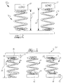
- FIG. 2 illustrates a problem in the manufacture of coil springs 16 as shown generally at 20.
- Two coil springs 16 are shown under a load 21, which is the same on both springs 16.
- the springs 16 may be manufactured to the same specifications and the springs 16 may be from the same lot.
- the height dimension of the springs 16 under a load 21, which will be hereafter called the load height dimension 22, can be seen to be different.
- the load height dimension 22 difference of supposedly identical springs 16, under the same load 21, is due to the fact that there may be variations in any spring 16.
- FIG 3 shows an aspect of applicants invention.
- Isolators 18 are provided of varying base height dimensions 19.
- the isolators 18 can be used on the top 23, the bottom 24, or both top 23 and bottom 24 of the coil spring 16, to achieve a more consistent overall load height dimension 22.
- a total height dimension 29 is the height of the spring 16 and isolators 18 assembled together, under a load 21. The use of the various isolators 18 allows the total assembled height dimension 29 to be kept relatively equal.
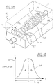
- An isolator 18 is shown in Figure 4 and has a base 25 with a bottom 27 surface and a top 28 surface.
- a base height dimension 19 is defined between the surfaces 27, 28.
- a circular protrusion 32 extends out of the top 28 surface of the base 25 to fit in the center 34 of the coil spring 16.
- a load 21 is placed on top 22 of the coil spring 16 and the height dimension of the coil spring 16 under load 21 is measured.
- the load 21 is consistent during each test.
- a tolerance range is set for the measured load height. If the load height is outside the tolerance range, the spring 16 may be discarded.
- the springs 16 may then be separated into one group of springs measuring on the high end and a group of springs measuring on the low end. Of course, more than two separate groups can be defined.
- a range 38 of load height data is shown plotted on an X, Y axis.
- a distribution 44 of the coil spring load height data shown will typically be bell shaped.
- One method of this invention uses this population information.
- a mean of the load height distribution 44 is calculated.
- the springs are sorted into two groups. One group includes springs that measure below the mean. For purposes of Figure 5 this group is illustrated as group A.
- Another group includes springs measuring above the mean, illustrated as group B.
- load height dimension 22 data is divided into two groups. However, the data may be divided into any number of groups under the following method.
- the coil springs16 from group B are assembled to isolators 18 with a predetermined base height of X.
- the coil spring 16 from group A are assembled to isolators 18 with base height of X plus .5 multiplied by range 38, (see Figure 5).
- the range 38 value is determined as an acceptable spread for the measured coil spring 16 load height values. That is, the range 38 need not extend to include all data, but may limit the extreme samples.
- the extra height of the isolators 18 used with Group A springs makes the combined height of the springs 16 and isolators 18 more consistent.
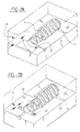
- FIG. 7A Another embodiment of the invention shown generally at 70 in Figures 7A and 7B, involves placing the coil spring 16 into a mold 56, 57 after the springs 16 load height is measured.
- the mold cavity 58 would take the same shape of an isolator (not shown).
- a spring 16 with a smaller load height is placed into a mold 56 with a larger base height portion 19 in the mold cavity 58.
- a spring 16 with the larger load height is placed into a mold 57 within the mold cavity 58 having a shorter base height 19.
- Elastomeric and/or polymer material is injected into the molds 56, 57 and the coil spring 16 and isolator 18 become a one piece assembly.
- more than two different molds 56, 57 and mold cavities 58 may be used to further reduce the tolerance on the overall assembled load height dimension 29 (i.e. the springs and molds could be further divided in small, medium and large heights, etc.).
- FIG. 8 Another method of forming an isolator (not shown) is shown schematically at 80 in Figure 8.
- a single mold 60, and single adjustable mold cavity 58 is used.
- a spring 16 is placed in the mold 60 and subjected to a load 21.
- the variable mold cavity 58 contains a plate 59 which is adjusted by pushing a plunger 62.
- the plunger 62 and plate 59 together adjust the mold cavity 60 base height dimension 19. Constant height can therefore be achieved when the spring 16 is under a load 21.
- the Figure 8 embodiment only shows this method schematically. In fact the load 21 would preferably be applied to the end of the spring associated with plate 59. A worker in the molding art would be able to develop an appropriate mold.
- the Figure 8 embodiment allows the combined height of each spring and isolator to be made equal.
- the earlier embodiments simply move the combined height to be more equal, within the incremental tolerances of the different isolator sizes.
- the invention has been described in an illustrative manner, and it is to be understood that the terminology which has been used is intended to be in the nature of words of description rather than of limitation. Although the inventive variation is achieved by varying the isolators, it should be understood that other spacers could provide the same variation.
Landscapes
- Engineering & Computer Science (AREA)
- General Engineering & Computer Science (AREA)
- Mechanical Engineering (AREA)
- Springs (AREA)
- Vehicle Body Suspensions (AREA)
Abstract
Description
Claims (13)
- A method of controlling the load height variability in coil springs used in a vehicle suspension system comprising:a.) forming a spring (16) having a particular height change in response to a particular load (21),b.) forming isolators (18) having various heights, and associating a particular isolator of a given height with a particular spring based upon said spring height,c.) assembling said spring and said isolators, andd.) installing said spring and said isolators into a suspension.
- A method as set forth in Claim 1, wherein step (b) is achieved by placing said spring in a mold (56, 57) and forming said isolator in said mold on said spring.
- A method as in Claim 2, wherein an isolator height dimension in said mold is changed to a particular dimension to ensure constant combined height of said spring and isolator.
- Method as in Claim 2 or 3, wherein at least two types of said molds are used, based upon the measured height of said springs.
- A method as in any preceding claim, wherein said springs are divided into at least two groups, with springs having a smaller load height placed into a first mold cavity (58) having a larger base height dimension, and springs having a larger load height placed into a second mold cavity (58) having a smaller base height dimension.
- A method as recited in Claim 5, wherein a mean value of spring heights for a load is determined, and a difference between a base height in said first and second molds is based on said mean value.
- A method as in Claim 1, wherein said isolators are formed remote from said springs and then added to said springs.
- A coil spring assembly for a vehicle suspension system (10) comprising:a coil spring (16) extending between two ends and having at least one isolator (18) disposed at one of said ends of said spring;said spring having a particular height change in response to a load and said isolator having a height based upon said height change of said spring; andsaid spring and said isolator are disposed in a vehicle suspension system.
- A coil spring assembly for a vehicle suspension system as in Claim 8, wherein said isolator is molded onto said spring.
- A coil spring assembly for a vehicle suspension system as in Claim 8 or Claim 9, wherein said isolator is sized to ensure that said spring and isolator assembly achieve a preset combined height.
- A coil spring assembly for a vehicle suspension system as in any one of Claims 8 to 10, wherein said isolators are formed separately and assembled to said spring.
- A coil spring assembly for a vehicle suspension system (10) comprising:a coil spring (16) extending between two ends and having at least one end attached to a spacer structure;said spring having a particular height change in response to a load, and said spacer having a height based upon said height change of said spring; andsaid spring and said spacer being disposed in a vehicle suspension system.
- An assembly as set forth in Claim 12, wherein said spacer is provided by an isolator (18) received at one end of said spring.
Applications Claiming Priority (2)
| Application Number | Priority Date | Filing Date | Title |
|---|---|---|---|
| US665426 | 1984-10-26 | ||
| US09/665,426 US6481702B1 (en) | 2000-09-20 | 2000-09-20 | Reduction of coil spring load height variability |
Publications (3)
| Publication Number | Publication Date |
|---|---|
| EP1191249A2 true EP1191249A2 (en) | 2002-03-27 |
| EP1191249A3 EP1191249A3 (en) | 2003-10-08 |
| EP1191249B1 EP1191249B1 (en) | 2006-06-28 |
Family
ID=24670061
Family Applications (1)
| Application Number | Title | Priority Date | Filing Date |
|---|---|---|---|
| EP01307798A Expired - Lifetime EP1191249B1 (en) | 2000-09-20 | 2001-09-13 | Reduction of coil spring load height variability |
Country Status (4)
| Country | Link |
|---|---|
| US (1) | US6481702B1 (en) |
| EP (1) | EP1191249B1 (en) |
| DE (1) | DE60121106T2 (en) |
| ES (1) | ES2267687T3 (en) |
Cited By (5)
| Publication number | Priority date | Publication date | Assignee | Title |
|---|---|---|---|---|
| WO2003004900A1 (en) * | 2001-07-06 | 2003-01-16 | Audi Ag | Method for disposing a helical compression spring |
| FR2944734A1 (en) * | 2009-04-27 | 2010-10-29 | Peugeot Citroen Automobiles Sa | MacPherson strut arrangement for motor vehicle wheel, has single spring mounted between lower and upper retainers, where upper retainer has two different predetermined axial heights for obtaining thrusts in predetermined rated thrust range |
| DE102014222177A1 (en) | 2014-10-30 | 2016-05-04 | Volkswagen Aktiengesellschaft | Spring system for a vehicle |
| CN106489042A (en) * | 2014-06-19 | 2017-03-08 | 日本发条株式会社 | Helical spring assembly |
| DE102017221652A1 (en) * | 2017-12-01 | 2019-06-06 | Volkswagen Aktiengesellschaft | Spring device for a vehicle wheel suspension |
Families Citing this family (5)
| Publication number | Priority date | Publication date | Assignee | Title |
|---|---|---|---|---|
| JP4010829B2 (en) * | 2002-02-21 | 2007-11-21 | 中央発條株式会社 | Coil spring manufacturing method and apparatus |
| JP2009531577A (en) * | 2006-01-31 | 2009-09-03 | ローベルト ボツシユ ゲゼルシヤフト ミツト ベシユレンクテル ハフツング | High pressure pump for supplying fuel to an internal combustion engine |
| DE102009012238A1 (en) * | 2009-03-07 | 2010-09-09 | Bayerische Motoren Werke Aktiengesellschaft | Modular system for accommodating suspension spring in wheel suspension of passenger car, has spring pads extending over sectors of support surfaces for entire end coil such that vehicle models are provided with respective pads at spring end |
| WO2011087087A1 (en) | 2010-01-18 | 2011-07-21 | 中央発條株式会社 | Spring characteristics correction method and spring characteristics correction device |
| CN202441794U (en) * | 2012-03-02 | 2012-09-19 | 喜临门家具股份有限公司 | Spiral pneumatic spring |
Family Cites Families (12)
| Publication number | Priority date | Publication date | Assignee | Title |
|---|---|---|---|---|
| US2409265A (en) * | 1944-05-04 | 1946-10-15 | American Steel & Wire Co | Classifier |
| US2610847A (en) * | 1951-08-21 | 1952-09-16 | Brenner B Fox | Correcting spring aligning spacer ring |
| US3578279A (en) * | 1969-09-10 | 1971-05-11 | Gen Electric | Resilient mounting means |
| US3862751A (en) * | 1972-09-28 | 1975-01-28 | Bernard L Schwaller | Dual stage compressor spring |
| FR2379731A1 (en) * | 1977-02-08 | 1978-09-01 | Snecma | LINEAR SPRING |
| DE2932500A1 (en) * | 1979-08-10 | 1981-02-12 | Hoesch Estel Werke Ag | SPRING PLATE FOR SCREW PRESSURE SPRINGS |
| DE2942135C2 (en) * | 1979-10-18 | 1987-05-14 | Volkswagen AG, 3180 Wolfsburg | Base made of rubber-elastic material for coil springs of a motor vehicle suspension |
| DE3341432C2 (en) * | 1983-11-12 | 1986-10-23 | PAIDOS GmbH, 4052 Korschenbroich | Play device |
| US5090657A (en) * | 1990-08-06 | 1992-02-25 | Tecumseh Products Company | Cable reinforced mounting system |
| EP0539955B1 (en) * | 1991-10-30 | 1998-02-18 | Togo Seisakusho Corporation | Spring assembly for automatic transmission of automotive vehicle and the like |
| US5467970A (en) * | 1994-06-06 | 1995-11-21 | General Motors Corporation | Vehicle suspension system with jounce bumper |
| US6254072B1 (en) * | 1999-03-31 | 2001-07-03 | Daimlerchrysler Corporation | Spring isolator and jounce bumper for a motor vehicle suspension |
-
2000
- 2000-09-20 US US09/665,426 patent/US6481702B1/en not_active Expired - Fee Related
-
2001
- 2001-09-13 EP EP01307798A patent/EP1191249B1/en not_active Expired - Lifetime
- 2001-09-13 ES ES01307798T patent/ES2267687T3/en not_active Expired - Lifetime
- 2001-09-13 DE DE60121106T patent/DE60121106T2/en not_active Expired - Fee Related
Cited By (8)
| Publication number | Priority date | Publication date | Assignee | Title |
|---|---|---|---|---|
| WO2003004900A1 (en) * | 2001-07-06 | 2003-01-16 | Audi Ag | Method for disposing a helical compression spring |
| FR2944734A1 (en) * | 2009-04-27 | 2010-10-29 | Peugeot Citroen Automobiles Sa | MacPherson strut arrangement for motor vehicle wheel, has single spring mounted between lower and upper retainers, where upper retainer has two different predetermined axial heights for obtaining thrusts in predetermined rated thrust range |
| CN106489042A (en) * | 2014-06-19 | 2017-03-08 | 日本发条株式会社 | Helical spring assembly |
| CN106489042B (en) * | 2014-06-19 | 2019-11-26 | 日本发条株式会社 | Helical spring assembly |
| DE102014222177A1 (en) | 2014-10-30 | 2016-05-04 | Volkswagen Aktiengesellschaft | Spring system for a vehicle |
| DE102014222177B4 (en) | 2014-10-30 | 2018-07-12 | Volkswagen Aktiengesellschaft | Spring system for a vehicle |
| DE102017221652A1 (en) * | 2017-12-01 | 2019-06-06 | Volkswagen Aktiengesellschaft | Spring device for a vehicle wheel suspension |
| DE102017221652B4 (en) * | 2017-12-01 | 2025-08-21 | Volkswagen Aktiengesellschaft | Spring device for a motor vehicle wheel suspension |
Also Published As
| Publication number | Publication date |
|---|---|
| ES2267687T3 (en) | 2007-03-16 |
| DE60121106T2 (en) | 2006-12-07 |
| EP1191249A3 (en) | 2003-10-08 |
| EP1191249B1 (en) | 2006-06-28 |
| US6481702B1 (en) | 2002-11-19 |
| DE60121106D1 (en) | 2006-08-10 |
Similar Documents
| Publication | Publication Date | Title |
|---|---|---|
| US6481702B1 (en) | Reduction of coil spring load height variability | |
| US8070171B2 (en) | Leveling shock absorber and strut assembly | |
| US7178795B2 (en) | Mounting assembly for a vehicle suspension component | |
| KR101177337B1 (en) | Axial spring rubber of axial box supporting device for railway vehicle and method of manufacturing therefor | |
| EP2762336A2 (en) | Vehicle-suspension shrinkable-tube producing device and a shrinkable-tube production method using same | |
| EP1455211B1 (en) | Lens mount with an integrated lens | |
| US5588209A (en) | Method and apparatus to manufacture stabilizer bars | |
| JPH05193319A (en) | Car suspension | |
| US4376572A (en) | Pivoting mirror device | |
| KR100212523B1 (en) | Constant number measuring system for the coil spring of a car | |
| US5003684A (en) | Method of manufacturing tubular vibration-insulating bushing | |
| DE202006018911U1 (en) | Vehicle-testing device for mechanical, preferably vibro-acoustic testing of components/vehicles has an electromagnetic actuator, a test device and a comparison unit | |
| JP2008143376A (en) | Manufacturing method of stabilizer bar with anti-vibration bush | |
| US20040102567A1 (en) | Elastomeric suspension spring for a motor vehicle and a suspension joint incorporating the spring | |
| JP2000241101A (en) | Dishing amount measuring apparatus for wheel fixing surface for automobile | |
| KR102764351B1 (en) | Top mount and top mount assembly for air spring for vehicle, and manufacturing method thereof | |
| CN116923719A (en) | Universal unmanned aerial vehicle profiling bracket | |
| EP3969778B1 (en) | Spring element, in particular jounce bumper, for a vehicle shock absorber | |
| US6612555B2 (en) | Elastomeric bearing unit for assemblies or chassis parts of vehicles | |
| JP2000110878A (en) | Manufacturing method of laminated rubber bearing | |
| CN121246100B (en) | Foam mold based on nano reinforced composite material and intelligent assembly method thereof | |
| LU103408B1 (en) | Spring system for a motor vehicle, motor vehicle and method for manufacturing a spring system | |
| JPH08257799A (en) | Powder molding die and its assembling method | |
| JPH0783280A (en) | Engine mount device | |
| JPH09273596A (en) | Vibration-proofing device |
Legal Events
| Date | Code | Title | Description |
|---|---|---|---|
| PUAI | Public reference made under article 153(3) epc to a published international application that has entered the european phase |
Free format text: ORIGINAL CODE: 0009012 |
|
| AK | Designated contracting states |
Kind code of ref document: A2 Designated state(s): AT BE CH CY DE DK ES FI FR GB GR IE IT LI LU MC NL PT SE TR |
|
| AX | Request for extension of the european patent |
Free format text: AL;LT;LV;MK;RO;SI |
|
| PUAL | Search report despatched |
Free format text: ORIGINAL CODE: 0009013 |
|
| AK | Designated contracting states |
Kind code of ref document: A3 Designated state(s): AT BE CH CY DE DK ES FI FR GB GR IE IT LI LU MC NL PT SE TR |
|
| AX | Request for extension of the european patent |
Extension state: AL LT LV MK RO SI |
|
| RIC1 | Information provided on ipc code assigned before grant |
Ipc: 7B 60G 11/54 B Ipc: 7F 16F 3/12 A Ipc: 7F 16F 1/12 B |
|
| 17P | Request for examination filed |
Effective date: 20040319 |
|
| AKX | Designation fees paid |
Designated state(s): DE ES FR GB IT |
|
| 17Q | First examination report despatched |
Effective date: 20050401 |
|
| GRAP | Despatch of communication of intention to grant a patent |
Free format text: ORIGINAL CODE: EPIDOSNIGR1 |
|
| GRAS | Grant fee paid |
Free format text: ORIGINAL CODE: EPIDOSNIGR3 |
|
| GRAA | (expected) grant |
Free format text: ORIGINAL CODE: 0009210 |
|
| AK | Designated contracting states |
Kind code of ref document: B1 Designated state(s): DE ES FR GB IT |
|
| REG | Reference to a national code |
Ref country code: GB Ref legal event code: FG4D |
|
| REF | Corresponds to: |
Ref document number: 60121106 Country of ref document: DE Date of ref document: 20060810 Kind code of ref document: P |
|
| ET | Fr: translation filed | ||
| REG | Reference to a national code |
Ref country code: ES Ref legal event code: FG2A Ref document number: 2267687 Country of ref document: ES Kind code of ref document: T3 |
|
| PLBE | No opposition filed within time limit |
Free format text: ORIGINAL CODE: 0009261 |
|
| STAA | Information on the status of an ep patent application or granted ep patent |
Free format text: STATUS: NO OPPOSITION FILED WITHIN TIME LIMIT |
|
| 26N | No opposition filed |
Effective date: 20070329 |
|
| PGFP | Annual fee paid to national office [announced via postgrant information from national office to epo] |
Ref country code: FR Payment date: 20080915 Year of fee payment: 8 |
|
| PGFP | Annual fee paid to national office [announced via postgrant information from national office to epo] |
Ref country code: GB Payment date: 20080917 Year of fee payment: 8 |
|
| PGFP | Annual fee paid to national office [announced via postgrant information from national office to epo] |
Ref country code: DE Payment date: 20080926 Year of fee payment: 8 |
|
| PGFP | Annual fee paid to national office [announced via postgrant information from national office to epo] |
Ref country code: ES Payment date: 20081021 Year of fee payment: 8 |
|
| PGFP | Annual fee paid to national office [announced via postgrant information from national office to epo] |
Ref country code: IT Payment date: 20080927 Year of fee payment: 8 |
|
| REG | Reference to a national code |
Ref country code: GB Ref legal event code: 732E Free format text: REGISTERED BETWEEN 20090820 AND 20090826 |
|
| REG | Reference to a national code |
Ref country code: FR Ref legal event code: TP |
|
| REG | Reference to a national code |
Ref country code: ES Ref legal event code: PC2A |
|
| GBPC | Gb: european patent ceased through non-payment of renewal fee |
Effective date: 20090913 |
|
| REG | Reference to a national code |
Ref country code: FR Ref legal event code: ST Effective date: 20100531 |
|
| PG25 | Lapsed in a contracting state [announced via postgrant information from national office to epo] |
Ref country code: DE Free format text: LAPSE BECAUSE OF NON-PAYMENT OF DUE FEES Effective date: 20100401 Ref country code: FR Free format text: LAPSE BECAUSE OF NON-PAYMENT OF DUE FEES Effective date: 20090930 |
|
| PG25 | Lapsed in a contracting state [announced via postgrant information from national office to epo] |
Ref country code: GB Free format text: LAPSE BECAUSE OF NON-PAYMENT OF DUE FEES Effective date: 20090913 |
|
| PG25 | Lapsed in a contracting state [announced via postgrant information from national office to epo] |
Ref country code: IT Free format text: LAPSE BECAUSE OF NON-PAYMENT OF DUE FEES Effective date: 20090913 |
|
| REG | Reference to a national code |
Ref country code: ES Ref legal event code: FD2A Effective date: 20110714 |
|
| PG25 | Lapsed in a contracting state [announced via postgrant information from national office to epo] |
Ref country code: ES Free format text: LAPSE BECAUSE OF NON-PAYMENT OF DUE FEES Effective date: 20110704 |
|
| PG25 | Lapsed in a contracting state [announced via postgrant information from national office to epo] |
Ref country code: ES Free format text: LAPSE BECAUSE OF NON-PAYMENT OF DUE FEES Effective date: 20090914 |