EP1191243A2 - Magnetic bearing apparatus of quick response - Google Patents
Magnetic bearing apparatus of quick response Download PDFInfo
- Publication number
- EP1191243A2 EP1191243A2 EP01118168A EP01118168A EP1191243A2 EP 1191243 A2 EP1191243 A2 EP 1191243A2 EP 01118168 A EP01118168 A EP 01118168A EP 01118168 A EP01118168 A EP 01118168A EP 1191243 A2 EP1191243 A2 EP 1191243A2
- Authority
- EP
- European Patent Office
- Prior art keywords
- magnetic bearing
- signal
- power amplifier
- bearing apparatus
- carrier frequency
- Prior art date
- Legal status (The legal status is an assumption and is not a legal conclusion. Google has not performed a legal analysis and makes no representation as to the accuracy of the status listed.)
- Withdrawn
Links
- 238000006073 displacement reaction Methods 0.000 claims description 23
- 238000010586 diagram Methods 0.000 description 6
- 230000015572 biosynthetic process Effects 0.000 description 5
- 238000003786 synthesis reaction Methods 0.000 description 5
- 230000006866 deterioration Effects 0.000 description 3
- 230000003321 amplification Effects 0.000 description 2
- 238000005229 chemical vapour deposition Methods 0.000 description 2
- 230000001934 delay Effects 0.000 description 2
- 238000004519 manufacturing process Methods 0.000 description 2
- 238000003199 nucleic acid amplification method Methods 0.000 description 2
- 239000004065 semiconductor Substances 0.000 description 2
- 230000002411 adverse Effects 0.000 description 1
- 238000001514 detection method Methods 0.000 description 1
- 230000002542 deteriorative effect Effects 0.000 description 1
- 238000003379 elimination reaction Methods 0.000 description 1
- 238000000034 method Methods 0.000 description 1
- 238000012986 modification Methods 0.000 description 1
- 230000004048 modification Effects 0.000 description 1
- 230000010355 oscillation Effects 0.000 description 1
- 229920006395 saturated elastomer Polymers 0.000 description 1
- 239000007787 solid Substances 0.000 description 1
- 239000000758 substrate Substances 0.000 description 1
Images





Classifications
-
- F—MECHANICAL ENGINEERING; LIGHTING; HEATING; WEAPONS; BLASTING
- F16—ENGINEERING ELEMENTS AND UNITS; GENERAL MEASURES FOR PRODUCING AND MAINTAINING EFFECTIVE FUNCTIONING OF MACHINES OR INSTALLATIONS; THERMAL INSULATION IN GENERAL
- F16C—SHAFTS; FLEXIBLE SHAFTS; ELEMENTS OR CRANKSHAFT MECHANISMS; ROTARY BODIES OTHER THAN GEARING ELEMENTS; BEARINGS
- F16C32/00—Bearings not otherwise provided for
- F16C32/04—Bearings not otherwise provided for using magnetic or electric supporting means
-
- F—MECHANICAL ENGINEERING; LIGHTING; HEATING; WEAPONS; BLASTING
- F16—ENGINEERING ELEMENTS AND UNITS; GENERAL MEASURES FOR PRODUCING AND MAINTAINING EFFECTIVE FUNCTIONING OF MACHINES OR INSTALLATIONS; THERMAL INSULATION IN GENERAL
- F16C—SHAFTS; FLEXIBLE SHAFTS; ELEMENTS OR CRANKSHAFT MECHANISMS; ROTARY BODIES OTHER THAN GEARING ELEMENTS; BEARINGS
- F16C32/00—Bearings not otherwise provided for
- F16C32/04—Bearings not otherwise provided for using magnetic or electric supporting means
- F16C32/0406—Magnetic bearings
- F16C32/044—Active magnetic bearings
- F16C32/0444—Details of devices to control the actuation of the electromagnets
- F16C32/0457—Details of the power supply to the electromagnets
-
- F—MECHANICAL ENGINEERING; LIGHTING; HEATING; WEAPONS; BLASTING
- F16—ENGINEERING ELEMENTS AND UNITS; GENERAL MEASURES FOR PRODUCING AND MAINTAINING EFFECTIVE FUNCTIONING OF MACHINES OR INSTALLATIONS; THERMAL INSULATION IN GENERAL
- F16C—SHAFTS; FLEXIBLE SHAFTS; ELEMENTS OR CRANKSHAFT MECHANISMS; ROTARY BODIES OTHER THAN GEARING ELEMENTS; BEARINGS
- F16C2360/00—Engines or pumps
- F16C2360/44—Centrifugal pumps
- F16C2360/45—Turbo-molecular pumps
Definitions
- the present invention relates to a magnetic bearing apparatus which is requested to have a quick response for high-speed rotary machines. More specifically, the present invention relates to a magnetic bearing apparatus for use in semiconductor device manufacturing apparatuses, having an advantage of being capable of supporting an object at low speed without any physical contact and having a solid yoke structure for reducing discharge gas from a magnetic circuit and improving anticorrosiveness, for example, a magnetic bearing apparatus suitable for a CVD (chemical vapor deposition) apparatus, a substrate rotating apparatus for RTP (rapid thermal processing) and a gas circulation fan.
- CVD chemical vapor deposition
- RTP rapid thermal processing
- a turbo molecular pump In the field of a semiconductor device manufacturing apparatus, a turbo molecular pump is well known among apparatuses in which magnetic bearing apparatuses are in particular widespread. Magnetic bearing apparatuses employed in almost all turbo molecular pumps are called as a control-type magnetic bearing apparatus.
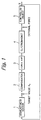
- Fig. 1 shows a structural example of such a control-type magnetic bearing apparatus in one degree of freedom.
- the magnetic bearing apparatus comprises a displacement sensor 1, a compensating device 2, a power amplifier 3 and an electromagnet 4.
- Power amplifier 3 supplies a control current to a coil wound around electromagnet 4 to generate a magnetic force, which magnetically supports a controlled object 5.
- a displacement X made by controlled object 5 is detected by displacement sensor 1 and is compared with a target value Xo.
- a deviation between X and Xo is input to power amplifier 3 through compensating device 2.
- a load to power amplifier 3 is electromagnet 4 and, thus, a delaying load.
- Power amplifier 3 drives electromagnet 4 by means of an output current which corresponds to an input signal.
- a relationship between the input signal and the output current indicates a delay characteristic.
- a loop is provided in order to feed back to the input of power amplifier 3 a coil current supplied to the coil of electromagnet 4.
- Fig. 2 shows a structural example of power amplifier 3.
- Power amplifier 3 comprises a control unit 3-1, a drive unit 3-2, a current detector 3-3 and a current signal feedback loop 3-4. From a view point of role, power amplifier 3 is generally divided into two parts, that is, control unit 3-1 and drive unit 3-2.
- Control unit 3-1 forms a signal S for controlling drive unit 3-2 on the basis of an input signal S1 received from compensating device 2 (Fig. 1) and a current feedback signal S2.
- Drive unit 3-2 supplies a coil current to the coil of electromagnet 4 on the basis of an output signal S3 of control unit 3-1.
- Control unit 3-1 is now explained, taking an example of a PWM (pulse width modulation) system, as shown in Fig. 3, widely employed today.
- Control unit 3-1 comprises signal regulators 3-3-1 and 3-1-2, a adding/subtracting device 3-1-3, a gain amplifier 3-1-4, a PWM carrier signal generator 3-1-5 and a PWM device (comparator) 3-1-6.
- Signal regulators 3-3-1 and 3-1-2, adding/subtracting device 3-1-3 and gain amplifier 3-1-4 form a signal synthesis and regulation unit designated generally by 3-1A.
- input signal S1 and current feedback signal S2 that is, a negatively fed back coil current of electromagnet 4 are fed through signal regulators 3-1-1 and 3-1-2 to gain amplifier 3-1-4 having a relatively large gain 10 - 100.
- PWM device (comparator) 3-1-6 compares the output of gain amplifier 3-1-4 with a reference carrier signal, such as a triangle wave signal, from PWM carrier signal generator 3-1-5 and produces output signal S3 that is a pulse width modulated signal. Pulse width modulated signal S3 is fed to drive unit 3-2, thereby causing a coil current I to be supplied to the coil of electromagnet 4.
- a reference carrier signal such as a triangle wave signal
- the gain equals to one (1) [A/V] if a ratio of an amount of feedback of coil current I to input signal S1 is equal to one.
- the gain is in inverse proportion to how much coil current I is fed back.
- the speed-of-response (follow-up response) is in proportion to a ratio of an amount of feedback of coil current I to input signal S1 and in proportion to a relatively large gain of gain amplifier 3-1-4.
- the present invention has been proposed in view of the above-described problems and an object of the present invention is to provide a magnetic bearing apparatus of a low cost and having a quick response.
- the present invention provides a magnetic bearing apparatus having a power amplifier for supplying a control current to a coil of an electromagnet of a control-type magnetic bearing, said apparatus characterized in that a non-linear component is provided in the rear of a stage where a control input signal of the power amplifier and a current feedback signal are added.
- the non-linear component may preferably be a comparator circuit.
- the non-linear component is disposed in the rear of the stage where the control input signal and the current feedback signal are added, it is possible to improve a speed-of-response of the power amplifier.
- a comparator capable of making a comparison with a reference potential to produce an output having a constant value of logical high or low is used as the non-linear component, it is possible to improve the speed-of-response of the power amplifier. This is because the comparator is equivalent to an amplifier having an approximately infinite gain magnification with respect to an input signal in the vicinity of the reference voltage.
- a magnetic bearing apparatus may further have a remover provided in the rear of the non-linear component for removing a displacement sensor carrier frequency signal band.
- a displacement sensor carrier frequency signal component can be removed from higher order harmonic components contained in a rectangular output signal of the non-linear component.
- a magnetic bearing apparatus may further have a remover provided in front of the non-linear component for removing a pulse width modulation (PWM) power amplifier carrier frequency signal band.
- PWM pulse width modulation
- a detection signal obtained from a coil current of the electromagnet contains more or less a PWM carrier frequency signal component.
- a signal component should be removed before feedback, but may not be removed sufficiently in some cases.
- a magnetic bearing apparatus may provide a first remover in front of the non-linear component for removing a pulse width modulation (PWM) power amplifier carrier frequency signal band and a second remover subsequently to the non-linear component for removing a displacement sensor carrier frequency signal band.
- PWM pulse width modulation
- the present invention can exhibit combined advantages brought about when the removers are positioned in front of and in the rear of the non-linear component, respectively.
- PWM pulse width modulation
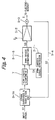
- Fig. 4 shows a structural example of a power amplifier of a magnetic bearing apparatus according to the present invention.
- the power amplifier corresponds to power amplifier 3 shown in Fig. 1.
- a non-linear component 7 is inserted between a signal synthesis and regulation unit 3-1A and a comparator circuit 3-1-6 in order to improve a speed-of-response of a power amplifier 3.
- Signal synthesis and regulation unit 3-1A has the same structure as as the one shown in Fig. 3.
- a comparator for example, is used as non-linear component 7.
- such a comparator capable of making a comparison with a reference potential to output a constant "high” or “low” value has an excellent speed-of-response and is equivalent to an amplifier having an approximately indefinite gain magnification with respect to an input signal in the vicinity of the reference voltage, which enables the speed-of-response of the power amplifier to be improved.
- Figs. 5(a) and 5(b) show examples of non-linear component 7, Fig. 5(a) showing a case where an operational amplifier 7-1 is utilized and Fig. 5(b) showing a case where a comparator having an open-collector output is utilized.
- Fig. 5(c) shows an input-output characteristic of non-linear component 7 shown in Figs. 5(a) and 5(b).
- Non-linear component 7 is equivalent to an amplifier having an approximately indefinite gain when an input is equal to zero or in the vicinity thereof. It is noted that non-linear component 7 is not limited to the structure as shown in Figs. 5(a) and 5(b) and can easily been realized by means of digital numerical arithmetic means.
- a part of signal regulator 3-1-1, a part of signal regulator 3-1-2, adding/subtracting device 3-1-3 and gain amplifier 3-1-4 in control unit 3-1 shown in Fig. 3 can be easily implemented as an analog circuit comprising an operational amplifier 107 and passive elements (resistors 101, 102 and 103, a capacitance 104 and Zener diodes 105 and 106) as shown in Fig. 6.
- a ratio of input signal S1 to current feedback signal S2 is interlocked to a gain magnification of gain amplifier 3-1-4, as described below. Consequently, the main purpose is to determine the ratio of input signal S1 to current feedback signal S2, and the gain magnification is preferably set to a relatively small value (1 - 10 times or around) in order to avoid internal saturation of operational amplifier 107.
- the ratio of input signal S1 to current feedback signal S2 is determined by resistance values R1 and R2 of resistors 101 and 102, respectively.
- the gain magnification is determined by R3/R1 and R3/R2.
- R3 is a resistance value of resistor 103. Consequently, input signal S1 and current feedback signal S2 are in inverse proportion to resistance values R1 and R2.
- Capacitance 104 is provided for the purpose of avoiding internal oscillation of operational amplifier 107.
- Zener diodes 105 and 106 are provided for the purpose of limiting a maximum amplitude of an output voltage. The purpose of such a limiting process is to maintain the output voltage less than the amplitude of a reference carrier signal S4 fed from a PWM carrier signal generator 3-1-5.
- a remover 8 is preferably provided at an output side of non-liner component 7 for removing a displacement sensor carrier frequency signal component (Fig. 1) so as to protect displacement sensor 1 (shown in Fig. 1).
- the output of non-linear component 7 is a rectangular-wave signal. If the displacement sensor carrier frequency signal component is contained in higher-order harmonics of the rectangular-wave signal, the carrier frequency signal may deteriorate the function of the displacement sensor (Please refer to Japanese Patent Laid-open No. 46296/98).
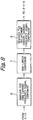
- a remover 9 is preferably provided in front of non-linear component 7 for removing a PWM carrier frequency signal component, as shown in Fig. 8.
- An output signal of a current detector 3-3 (Fig. 4) for detecting a coil current I of electromagnet 4 contains more or less the PWM carrier frequency signal component.
- the contained PWM carrier frequency signal component should be removed before feedback, but it may happen that such a signal component cannot be removed sufficiently.
- Remover 9 for removing the PWM carrier frequency signal component is preferably positioned in front of non-liner component 7, since gain amplifier 3-1-4 in signal synthesis and regulation unit 3-1A operates to amplify a signal from adding/subtracting device 3-1-3.
- non-liner component 7 is, as shown in Fig. 4, inserted between signal synthesis and regulation unit 3-1A and comparator circuit 3-1-6 in order to improve a speed-of-response of the gain amplifier.
- Remover 8 is provided at an output side of non-linear component 7 for removing a displacement sensor carrier frequency signal component and remover 9 is provided in front of non-liner component for removing a PWM carrier frequency signal component.
- Figs. 9(a) - 9(c) are used to explain removers 8 and 9.
- Fig. 9(a) shows a remover 110, an input signal Sin and an output signal Sout
- LPF lowpass filter
- BEF band-elimination filter
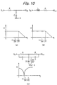
- Figs. 10(a) and 10(b) show structural examples of an LPF as a passive remover and a characteristic thereof.
- R denotes a resistor
- C a capacitance
- L an inductance
- E ground reference voltage
- f a frequency
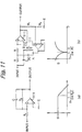
- Figs. 11(a) and 11(b) show structural examples of an LPF as an active remover and a characteristic thereof.
- R denotes a resistor
- C a capacitance
- L an inductance
- E ground reference voltage
- f a frequency
- 111 an operational amplifier.
Landscapes
- Engineering & Computer Science (AREA)
- General Engineering & Computer Science (AREA)
- Physics & Mathematics (AREA)
- Electromagnetism (AREA)
- Mechanical Engineering (AREA)
- Magnetic Bearings And Hydrostatic Bearings (AREA)
- Connection Of Motors, Electrical Generators, Mechanical Devices, And The Like (AREA)
Abstract
Description
Claims (5)
- A magnetic bearing apparatus having a power amplifier for supplying a control current to a coil of an electromagnet of a control-type magnetic bearing, said apparatus characterized in that a non-linear component is provided in the rear of a stage where a control input signal of said power amplifier and a current feedback signal are added.
- A magnetic bearing apparatus as claimed in claim 1, characterized in that said non-linear component is a conparator circuit.
- A magnetic bearing apparatus as claimed in claim 1 or 2, characterized in that a remover is provided at an output side of said non-linear component for removing a displacement sensor carrier frequency signal band.
- A magnetic bearing apparatus as claimed in claim 1 or 2. characterized in that a remover is provided at an input side of said non-linear component for removing a pulse width modulation (PWM) power amplifier carrier frequency signal band.
- A magnetic bearing apparatus as claimed in claim 1 or 2. characterized in that a first remover is provided at an input side of said non-linear component for removing a pulse width modulation (PWM) power amplifier carrier frequency signal band and that a second remover is provided at an output side of said non-linear component for removing a displacement sensor carrier frequency signal band.
Applications Claiming Priority (2)
| Application Number | Priority Date | Filing Date | Title |
|---|---|---|---|
| JP2000276845A JP2002089559A (en) | 2000-09-12 | 2000-09-12 | Magnetic bearing device |
| JP2000276845 | 2000-09-12 |
Publications (2)
| Publication Number | Publication Date |
|---|---|
| EP1191243A2 true EP1191243A2 (en) | 2002-03-27 |
| EP1191243A3 EP1191243A3 (en) | 2004-01-07 |
Family
ID=18762256
Family Applications (1)
| Application Number | Title | Priority Date | Filing Date |
|---|---|---|---|
| EP01118168A Withdrawn EP1191243A3 (en) | 2000-09-12 | 2001-07-26 | Magnetic bearing apparatus of quick response |
Country Status (4)
| Country | Link |
|---|---|
| US (1) | US20020047405A1 (en) |
| EP (1) | EP1191243A3 (en) |
| JP (1) | JP2002089559A (en) |
| KR (1) | KR20020020990A (en) |
Cited By (1)
| Publication number | Priority date | Publication date | Assignee | Title |
|---|---|---|---|---|
| WO2011147235A1 (en) * | 2010-05-26 | 2011-12-01 | 刘建 | Device and method of fan speed regulation |
Families Citing this family (6)
| Publication number | Priority date | Publication date | Assignee | Title |
|---|---|---|---|---|
| US6921997B2 (en) * | 2002-12-23 | 2005-07-26 | National Chung Cheng University | Active magnetic bearing with improved configuration reference cited |
| US20050000452A1 (en) * | 2003-05-16 | 2005-01-06 | Kordina Olof Claes Erik | Electromagnetic rotation of platter |
| US7830056B2 (en) * | 2005-07-05 | 2010-11-09 | Ebara Corporation | Magnetic bearing device and method |
| JP5025505B2 (en) * | 2008-01-24 | 2012-09-12 | 株式会社荏原製作所 | Magnetic bearing device |
| DE102010013682B4 (en) * | 2010-04-01 | 2020-06-10 | Siemens Aktiengesellschaft | Method for adapting a resistance value of an electromagnet of a magnetic bearing and for determining the position of an object stored in a magnetic bearing without sensors, taking into account the adapted resistance value |
| CN110996455B (en) * | 2019-12-31 | 2022-01-28 | 上海晶丰明源半导体股份有限公司 | Dimming control circuit, chip comprising same and dimming control method |
Family Cites Families (6)
| Publication number | Priority date | Publication date | Assignee | Title |
|---|---|---|---|---|
| US3146038A (en) * | 1962-02-07 | 1964-08-25 | Gen Motors Corp | Three-axis magnetic suspension |
| US4983869A (en) * | 1989-08-08 | 1991-01-08 | Sundstrand Corporation | Magnetic bearing |
| US5179308A (en) * | 1992-01-14 | 1993-01-12 | Charles Stark Draper Laboratory, Inc. | High-speed, low-loss antifriction bearing assembly |
| US5666013A (en) * | 1992-12-07 | 1997-09-09 | Seiko Seiki Kabushiki Kaisha | Magnetic bearing |
| JP3478876B2 (en) * | 1994-09-06 | 2003-12-15 | 株式会社 日立インダストリイズ | Excitation controller for magnetic bearing |
| JP3701115B2 (en) * | 1998-02-12 | 2005-09-28 | 株式会社荏原製作所 | Magnetic bearing control device |
-
2000
- 2000-09-12 JP JP2000276845A patent/JP2002089559A/en active Pending
-
2001
- 2001-07-26 EP EP01118168A patent/EP1191243A3/en not_active Withdrawn
- 2001-07-26 US US09/912,332 patent/US20020047405A1/en not_active Abandoned
- 2001-07-27 KR KR1020010045407A patent/KR20020020990A/en not_active Withdrawn
Cited By (1)
| Publication number | Priority date | Publication date | Assignee | Title |
|---|---|---|---|---|
| WO2011147235A1 (en) * | 2010-05-26 | 2011-12-01 | 刘建 | Device and method of fan speed regulation |
Also Published As
| Publication number | Publication date |
|---|---|
| JP2002089559A (en) | 2002-03-27 |
| KR20020020990A (en) | 2002-03-18 |
| US20020047405A1 (en) | 2002-04-25 |
| EP1191243A3 (en) | 2004-01-07 |
Similar Documents
| Publication | Publication Date | Title |
|---|---|---|
| JP4746619B2 (en) | Magnetic bearing device and magnetic bearing method | |
| JP3701115B2 (en) | Magnetic bearing control device | |
| JP2001177919A (en) | Magnetically levitated control apparatus | |
| US11015609B2 (en) | Magnetic levitation control device and vacuum pump | |
| US20020047405A1 (en) | Magnetic bearing apparatus of quick response | |
| CN1199502C (en) | Temperature Compensation Circuit for Automatic Gain Control Circuit | |
| US5666463A (en) | Reduction of electric motor surge current by non-linear limiting of rate of change of angular velocity | |
| WO2004057754A1 (en) | Method and apparatus for efficient amplification | |
| JP3070355B2 (en) | Solenoid drive control device for automatic transmission | |
| CN113474567B (en) | Control device and vacuum pump equipped with the control device | |
| JP3306893B2 (en) | Magnetic bearing device | |
| JPH0659604B2 (en) | Ultrasonic processing equipment | |
| JP2900677B2 (en) | Power amplifier | |
| JP3257033B2 (en) | Automatic gain control amplifier | |
| JP3087771B2 (en) | Current control device | |
| JPH08149876A (en) | Motor drive | |
| KR100254453B1 (en) | A detecting device for driving voltage feedback of a solenoid | |
| JP3218653B2 (en) | Magnetic bearing control device | |
| JPS61286609A (en) | Control device of control type radial magnetic bearing | |
| JP2001290504A (en) | Control device | |
| SU1672583A1 (en) | Correcting amplifier of scan signal of electron beam | |
| JPH1187136A (en) | Magnetic levitation system | |
| JPH0458309A (en) | High frequency power source | |
| JPH07114420A (en) | Vibration control device and method | |
| JPH08202460A (en) | Control circuit |
Legal Events
| Date | Code | Title | Description |
|---|---|---|---|
| PUAI | Public reference made under article 153(3) epc to a published international application that has entered the european phase |
Free format text: ORIGINAL CODE: 0009012 |
|
| AK | Designated contracting states |
Kind code of ref document: A2 Designated state(s): AT BE CH CY DE DK ES FI FR GB GR IE IT LI LU MC NL PT SE TR |
|
| AX | Request for extension of the european patent |
Free format text: AL;LT;LV;MK;RO;SI |
|
| PUAL | Search report despatched |
Free format text: ORIGINAL CODE: 0009013 |
|
| AK | Designated contracting states |
Kind code of ref document: A3 Designated state(s): AT BE CH CY DE DK ES FI FR GB GR IE IT LI LU MC NL PT SE TR |
|
| AX | Request for extension of the european patent |
Extension state: AL LT LV MK RO SI |
|
| AKX | Designation fees paid | ||
| REG | Reference to a national code |
Ref country code: DE Ref legal event code: 8566 |
|
| STAA | Information on the status of an ep patent application or granted ep patent |
Free format text: STATUS: THE APPLICATION IS DEEMED TO BE WITHDRAWN |
|
| 18D | Application deemed to be withdrawn |
Effective date: 20040708 |