EP1191221A1 - Pressure regulator - Google Patents
Pressure regulator Download PDFInfo
- Publication number
- EP1191221A1 EP1191221A1 EP01308107A EP01308107A EP1191221A1 EP 1191221 A1 EP1191221 A1 EP 1191221A1 EP 01308107 A EP01308107 A EP 01308107A EP 01308107 A EP01308107 A EP 01308107A EP 1191221 A1 EP1191221 A1 EP 1191221A1
- Authority
- EP
- European Patent Office
- Prior art keywords
- pressure
- piston member
- fuel
- pressure regulator
- pump
- Prior art date
- Legal status (The legal status is an assumption and is not a legal conclusion. Google has not performed a legal analysis and makes no representation as to the accuracy of the status listed.)
- Granted
Links
Images


Classifications
-
- G—PHYSICS
- G05—CONTROLLING; REGULATING
- G05D—SYSTEMS FOR CONTROLLING OR REGULATING NON-ELECTRIC VARIABLES
- G05D16/00—Control of fluid pressure
- G05D16/04—Control of fluid pressure without auxiliary power
- G05D16/10—Control of fluid pressure without auxiliary power the sensing element being a piston or plunger
- G05D16/103—Control of fluid pressure without auxiliary power the sensing element being a piston or plunger the sensing element placed between the inlet and outlet
-
- F—MECHANICAL ENGINEERING; LIGHTING; HEATING; WEAPONS; BLASTING
- F02—COMBUSTION ENGINES; HOT-GAS OR COMBUSTION-PRODUCT ENGINE PLANTS
- F02M—SUPPLYING COMBUSTION ENGINES IN GENERAL WITH COMBUSTIBLE MIXTURES OR CONSTITUENTS THEREOF
- F02M37/00—Apparatus or systems for feeding liquid fuel from storage containers to carburettors or fuel-injection apparatus; Arrangements for purifying liquid fuel specially adapted for, or arranged on, internal-combustion engines
- F02M37/0011—Constructional details; Manufacturing or assembly of elements of fuel systems; Materials therefor
- F02M37/0023—Valves in the fuel supply and return system
- F02M37/0029—Pressure regulator in the low pressure fuel system
-
- F—MECHANICAL ENGINEERING; LIGHTING; HEATING; WEAPONS; BLASTING
- F02—COMBUSTION ENGINES; HOT-GAS OR COMBUSTION-PRODUCT ENGINE PLANTS
- F02M—SUPPLYING COMBUSTION ENGINES IN GENERAL WITH COMBUSTIBLE MIXTURES OR CONSTITUENTS THEREOF
- F02M37/00—Apparatus or systems for feeding liquid fuel from storage containers to carburettors or fuel-injection apparatus; Arrangements for purifying liquid fuel specially adapted for, or arranged on, internal-combustion engines
- F02M37/0047—Layout or arrangement of systems for feeding fuel
- F02M37/0052—Details on the fuel return circuit; Arrangement of pressure regulators
- F02M37/0058—Returnless fuel systems, i.e. the fuel return lines are not entering the fuel tank
-
- G—PHYSICS
- G05—CONTROLLING; REGULATING
- G05D—SYSTEMS FOR CONTROLLING OR REGULATING NON-ELECTRIC VARIABLES
- G05D16/00—Control of fluid pressure
- G05D16/024—Controlling the inlet pressure, e.g. back-pressure regulator
-
- Y—GENERAL TAGGING OF NEW TECHNOLOGICAL DEVELOPMENTS; GENERAL TAGGING OF CROSS-SECTIONAL TECHNOLOGIES SPANNING OVER SEVERAL SECTIONS OF THE IPC; TECHNICAL SUBJECTS COVERED BY FORMER USPC CROSS-REFERENCE ART COLLECTIONS [XRACs] AND DIGESTS
- Y10—TECHNICAL SUBJECTS COVERED BY FORMER USPC
- Y10T—TECHNICAL SUBJECTS COVERED BY FORMER US CLASSIFICATION
- Y10T137/00—Fluid handling
- Y10T137/7722—Line condition change responsive valves
- Y10T137/7837—Direct response valves [i.e., check valve type]
- Y10T137/785—With retarder or dashpot
- Y10T137/7852—End of valve moves inside dashpot chamber
Definitions
- This invention relates to a pressure regulator suitable for use in regulating the outlet pressure of a low pressure, transfer pump of a fuel system for a compression ignition internal combustion engine.
- the vane pump may be provided with a regulator of the type illustrated in Figure 1, comprising a sleeve 10 within which a piston member 12 is slidable.
- the piston member 12 is biased by means of a spring 14 and is moveable under the action of the fuel pressure at the outlet of the transfer pump.
- the piston member 12 closes an outlet 16 defined within the sleeve 10 to prevent fuel flowing through the outlet 16 to the inlet side of the transfer pump.
- the piston member 12 is moveable within the sleeve 10 to a position in which the outlet 16 is open to allow fuel to return to the inlet side of the transfer pump.
- the degree to which the outlet 16 is opened depends upon the magnitude of the pressure applied to the piston member 12.
- the regulator can be set in such a manner that the outlet pressure of the transfer pump, as regulated by the pressure regulator, is related to the engine and pump speed in a desired manner.
- the pressure at the outlet of the transfer pump is used to control various aspects of fuel system operation.
- the pressure at the outlet of the transfer pump is used to adjust the maximum fuelling level of a high pressure fuel pump with which the transfer pump is associated.
- setting of such transfer pumps is difficult as the relationship between the outlet pressure and speed varies from pump to pump as a result of production variations.
- CH 690 191 A5 describes a pressure relief valve for relieving fluid pressure within a load chamber.
- the pressure relief valve is of the type having a valve needle biased towards a valve seating by means of a spring load. The valve needle is caused to lift away from the valve seating in the event that fluid pressure within the load chamber exceeds a predetermined amount, thereby opening communication between the load chamber and a low pressure drain.
- the pressure relief valve also includes a piston which is exposed to fluid pressure within a control chamber and which is engageable with a movable piece to alter the spring load acting on the valve needle. By varying fluid pressure within the control chamber, the fluid pressure at which the valve needle is caused to lift from its seating can be varied.
- the pressure relief valve is of the "plug-in-hole" type in which the valve needle extends into an opening in an insert which defines the valve seating. If fluid pressure within the load chamber is less than the predetermined relief pressure, the pressure relief valve is in a plugged position in which the valve needle extends into the opening and seats against the valve seating to completely close the opening, closing communication between the load chamber and the low pressure drain. If fluid pressure within the load chamber exceeds the predetermined relief pressure, the pressure relief valve is opened and the valve needle lifts off the valve seating to relieve pressure in the load chamber.
- a pressure regulator for use in regulating the outlet pressure of a pump for use in an engine, the pressure regulator comprising a piston member which is moveable within a bore provided in a regulator housing with respect to an outlet opening under the influence of fluid pressure acting on the piston member to control the degree by which the outlet opening is obscured, the pressure regulator comprising a biasing arrangement for applying a biasing force to the piston member which opposes the pressure of fluid acting on the piston member, wherein the biasing arrangement comprises a moveable abutment member which is cooperable with a stop member so as to terminate movement of the abutment member when the abutment member moves into engagement with the stop member, in use, thereby to vary the rate at which the displacement of the piston member varies with fluid pressure acting on the piston member, the stop member having a pre-set fixed position relative to the regulator housing.
- the biasing arrangement comprises a spring assembly comprising first and second spring means.
- first and second spring means take the form of first and second compression springs.
- the regulator housing preferably takes the form of a sleeve. It will be appreciated that the regulator housing may include two or more housing parts secured together, or may be a unitary part.
- the position of the stop member relative to the regulator housing is adjustable to permit adjustment of a pre-set fluid pressure at which the abutment member is caused to move into engagement with the stop member.
- the piston member When fluid pressure acting on the piston member exceeds the pre-set fluid pressure, the piston member is moved, against the biasing force due to the biasing arrangement, through a sufficient distance to cause the abutment member to engage the stop member.
- the rate at which displacement of the piston member varies with fluid pressure applied to the piston member is determined by the characteristics of both the first and second spring means.
- the second spring means When the moveable abutment member moves into engagement with the stop member movement of the abutment member is terminated, the second spring means is disabled and the rate at which displacement of the piston member varies with fluid pressure is altered.
- the rate at which displacement of the piston member varies with fluid pressure applied to the piston member is determined by the characteristic of only the first spring means.
- the predetermined fluid pressure at which the moveable abutment member moves into engagement with the stop member can be adjusted by adjusting the position of the stop member relative to the regulator housing.
- the speed of the associated engine is related to the pressure of fuel acting on the piston member.
- the pressure regulator can therefore be adjusted to give the required transfer pressure-engine speed characteristic.
- the invention provides the advantage that, as the pressure-speed characteristic of the pump can be adjusted, pump to pump variations can be compensated for.
- the pressure-speed characteristic of the pump can also be selected so as to match the requirements of the particular engine.
- the stop member takes the form of an adjustment screw.
- the pressure regulator preferably comprises an adjustment member for adjusting the pre-load of the biasing arrangement.
- the adjustment member takes the form of a further adjustment screw.
- At least a part of the stop member extends through a further bore provided in the adjustment member.
- the moveable abutment member conveniently includes an annular region defining first and second abutment surfaces, the abutment member being arranged such that the first abutment surface is in abutment with one end of the first spring means and the second abutment surface is in abutment with one end of the second spring means.
- the piston member itself is arranged to obscure the outlet opening, rather than any component carried by or otherwise coupled to the piston member.
- the piston member shaped to cooperate with the outlet opening so as to vary the extent to which the outlet opening is obscured, thereby to provide progressive opening of the outlet opening depending upon the extent to which the piston member is displaced.
- the piston member is of generally cylindrical form and has a generally cylindrical outer surface which cooperates with the outlet opening to vary the extent to which the outlet opening is obscured, depending on the position of the piston member within the bore.
- the diameter of the piston member and the diameter of the bore are preferably selected to ensure movement of the piston member within the bore is guided.
- the piston member is exposed to fuel pressure within an inlet chamber defined by the bore within which the piston moves.
- the piston member is arranged such that it can completely obscure the outlet opening to prevent fuel flow from the inlet chamber through the outlet opening.
- the pressure regulator provides a continuous pressure regulating function as the piston is urged to move against the spring load upon increasing fuel pressure within the inlet chamber.
- a transfer pump for use in supplying fuel to a high pressure pump for an engine comprises a pump outlet through which fuel is supplied at a pressure dependent upon engine speed to the high pressure pump, the transfer pump comprising a pressure regulator as herein described which is arranged to regulate the pressure of fuel delivered by the transfer pump to the high pressure pump, in use.
- the pressure regulator of the transfer pump comprises an inlet region defined by the bore within which the piston member of the pressure regulator moves to vary the extent to which the outlet opening is obscured, the pump outlet being arranged to deliver fuel to the inlet region at a pressure dependent upon the engine speed.
- the second aspect of the invention may include any one or more of the preferred or optional features of the first aspect of the invention.
- a fuel system for supplying fuel to an engine comprises a transfer pump for delivering fuel at relatively low, regulated pressure to a high pressure fuel pump, the high pressure fuel pump being arranged to deliver fuel to the engine, wherein the fuel system comprises a pressure regulator as herein described which is arranged to regulate the pressure of fuel delivered by the transfer pump to the high pressure pump, in use.
- Figure 2 illustrates a pressure regulator for use in regulating the outlet pressure of a transfer pump 21 which is used to supply fuel to an inlet of a high pressure fuel pump (not shown) for supplying fuel to a common rail or a distributed pumping system.
- the transfer pump 21 is arranged to draw fuel from a fuel reservoir 23 and supplies fuel at a relatively low pressure to the high pressure fuel pump.
- the pressure regulator comprises a sleeve or regulator housing 20 provided with a bore 22 within which a piston member 24 is moveable.
- the piston member 24 is of generally cylindrical form, the diameter of the piston member 24 and the diameter of the bore 22 being selected to ensure movement of the piston member 24 within the bore 22 is guided.
- the sleeve 20 is provided with an outlet opening 36 positioned such that, depending upon the position of the piston member 24 within the bore 22, the outlet opening 36 is either fully obscured by the cylindrical outer surface of the piston member 24, is partially obscured by the outer surface of the piston member 24 or is fully open.
- the outlet opening 36 communicates with the fuel reservoir 23 so as to regulate the outlet pressure of the pump 21.
- One end of the piston member 24 defines a surface 24 a which is exposed to fuel pressure at the outlet of the transfer pump 21 in an inlet region or inlet chamber 31 defined by the bore 22.
- the pressure of fuel in the inlet region 31 determines the position of the piston member 24 within the bore 22 and, hence, determines the rate of flow of fuel through the outlet opening 36.
- the piston member 24 gradually opens the outlet opening 36 depending on fuel pressure within the inlet region 31, as described in further detail below.
- the pressure regulator also includes a spring assembly 25 including first and second springs 26, 30, the spring assembly 25 being arranged to apply a biasing force to the piston member 24 which opposes the force due to fuel pressure acting on the piston member 24.
- the spring assembly 25 also includes an abutment member 28 which is moveable within the bore 22 and is engageable with a first adjustment member 34 in the form of a stop member upon movement of the abutment member 28 beyond a predetermined amount, as will be described in further detail hereinafter.
- the moveable abutment member 28 includes an annular region 28 a and is arranged between the first and second springs 26, 30 such that one end of the first spring 26 is in abutment with a first abutment surface defined by the annular region 28 a of the abutment member 28 and one end of the second spring 30 is in abutment with an opposing abutment surface defined by the annular region 28 a of the abutment member 28.
- the end of the second spring 30 remote from the abutment member 28 is in engagement with a further adjustment member 32 provided with a through bore through which the stop 34 extends, the adjustment member 32 being in screw threaded engagement with the sleeve 20 so as to permit the position of the adjustment member 32 relative to the sleeve 20 to be varied.
- the pre-load of the spring assembly 25 can be adjusted by adjusting the position of the adjustment member 32 relative to the sleeve 20.
- the stop 34 and the adjustment member 32 take the form of adjustment screws.
- the abutment member 28 is provided with a first drilling 27 in communication with a second drilling 29 provided in the stop 34.
- the provision of the drillings 27, 29 permits the region of the bore 22 within which the first spring 26 is arranged to be vented, thereby preventing the piston member 24 becoming hydraulically locked within the sleeve 20.
- the provision of the drillings 27, 29 allows the effects of viscosity on the operation of the pump to be compensated for ("viscosity compensation"). It will be appreciated that, although a relatively narrow clearance is defined between the piston member 24 and the bore 22, the dimensions of the clearance are such that movement of the piston member 24 within the bore 22 is guided.
- the abutment member 28 occupies a position in which it is spaced away from the surface 34 a of the stop 34, the position of the adjustment member 32 relative to the sleeve 20 being selected so as to provide the desired pre-load of the spring assembly 25.
- fuel pressure at the outlet of the transfer pump 21, and hence fuel pressure in the inlet region 31 is also increased, thereby causing the force applied to the surface 24 a of the piston member 24 to be increased.
- the outlet opening 36 will be opened progressively from a fully obscured state, in which the outer surface of the piston member 24 breaks communication completely (except for minimal fuel leakage) between the inlet region 31 and the outlet opening 36, and a partially obscured state in which the outer surface of the piston member 24 partially obscures the outlet opening 36.
- the extent to which the outlet opening 36 is obscured will also vary progressively with increasing fuel pressure within the inlet region 31 from a state in which the outlet opening 36 is partially obscured and a state in which the outlet opening 36 is opened to a maximum extent. It will therefore be appreciated that during both the first stage of operation, when both the first and second spring forces act on the piston member 24, and the second stage of operation, when only the first spring force acts on the piston member 24, the extent to which the outlet opening 36 is uncovered by the piston member 24 will vary progressively as fuel pressure in the inlet region 31 increases, even though the rate of displacement of the piston member 24 with fluid pressure will be different during the first and second stages.
- the pressure regulator is configured such that, during both the first and second stages of operation, there is an approximately linear relationship between the uncovered flow area presented by the outlet opening 36 and fuel pressure in the inlet region 31.
- the characteristics of the first and second springs are preferably selected to ensure that, when fuel pressure within the inlet region 31 reaches a maximum value for the particular pump/engine application and the outlet opening 36 is opened to the maximum extent by the piston member 24 (i.e. the second stage of operation), the piston member 24 is in a position in which the outlet opening 36 is only partially obscured by the outer surface of the piston member 24.
- Figure 3 shows the relationship between the regulated pump outlet pressure (i.e. in the inlet region 31) and engine speed.
- the force due to fuel at the outlet of the pump acting on the surface 24 a of the piston member 24 is sufficient to cause the abutment member 28 to move into engagement with the stop 34, thereby terminating movement of the abutment member 28 and disabling the second spring 30.
- the relationship between pump outlet pressure and engine speed is therefore governed only by the spring characteristic of the first spring 26.
- the engine speed C at which the second spring 30 becomes disabled is determined by the pre-set, fixed position of the stop 34 within the bore 22.
- the required fuel pressure at which the second spring 30 becomes disabled can be pre-set to the desired value.
- the engine speed C at which the pressure-engine speed characteristic changes is therefore selected by adjusting the position of the stop 34 within the bore 22 prior to use of the pump.
- the present invention provides the advantage that the pressure-engine speed characteristic of the pump can be adjusted by adjusting the position of the stop 34 and the adjustment member 32, thereby allowing pump to pump variations to be compensated for.
- the invention also provides the advantage that the pressure-engine speed characteristic of the pump can be tailored so as to ensure the required transfer pressure is achieved at the two speeds (e.g. speeds D and E in Figure 3) at which emission levels are measured for the purposes of regulatory approval.
- the rate of variation of transfer pressure with engine speed is substantially linear and so it is only possible to ensure the desired transfer pressure is achieved at one of the critical emissions speeds.
- the present invention is also advantageous in that the adjustable pressure regulator occupies a relatively small volume of space.
Landscapes
- Engineering & Computer Science (AREA)
- Physics & Mathematics (AREA)
- Chemical & Material Sciences (AREA)
- Combustion & Propulsion (AREA)
- Mechanical Engineering (AREA)
- General Engineering & Computer Science (AREA)
- Fluid Mechanics (AREA)
- General Physics & Mathematics (AREA)
- Automation & Control Theory (AREA)
- Fuel-Injection Apparatus (AREA)
- Control Of Fluid Pressure (AREA)
Abstract
Description
- This invention relates to a pressure regulator suitable for use in regulating the outlet pressure of a low pressure, transfer pump of a fuel system for a compression ignition internal combustion engine.
- It is known to use, as the transfer pump for use in a fuel system, a vane pump which is arranged to operate at a speed associated with engine speed. The vane pump may be provided with a regulator of the type illustrated in Figure 1, comprising a
sleeve 10 within which apiston member 12 is slidable. Thepiston member 12 is biased by means of aspring 14 and is moveable under the action of the fuel pressure at the outlet of the transfer pump. When thepiston member 12 is in the position shown in Figure 1, thepiston member 12 closes anoutlet 16 defined within thesleeve 10 to prevent fuel flowing through theoutlet 16 to the inlet side of the transfer pump. Thepiston member 12 is moveable within thesleeve 10 to a position in which theoutlet 16 is open to allow fuel to return to the inlet side of the transfer pump. - The degree to which the
outlet 16 is opened depends upon the magnitude of the pressure applied to thepiston member 12. By appropriate selection of the size of thepiston member 12 and thespring 14, the regulator can be set in such a manner that the outlet pressure of the transfer pump, as regulated by the pressure regulator, is related to the engine and pump speed in a desired manner. - The pressure at the outlet of the transfer pump, as modified by the pressure regulator, is used to control various aspects of fuel system operation. For example, in some arrangements the pressure at the outlet of the transfer pump, as modified by the pressure regulator, is used to adjust the maximum fuelling level of a high pressure fuel pump with which the transfer pump is associated. However, it has been found that setting of such transfer pumps is difficult as the relationship between the outlet pressure and speed varies from pump to pump as a result of production variations.
- It is an object of the present invention to remove or alleviate this problem.
- By way of background to the present invention, CH 690 191 A5 describes a pressure relief valve for relieving fluid pressure within a load chamber. The pressure relief valve is of the type having a valve needle biased towards a valve seating by means of a spring load. The valve needle is caused to lift away from the valve seating in the event that fluid pressure within the load chamber exceeds a predetermined amount, thereby opening communication between the load chamber and a low pressure drain. The pressure relief valve also includes a piston which is exposed to fluid pressure within a control chamber and which is engageable with a movable piece to alter the spring load acting on the valve needle. By varying fluid pressure within the control chamber, the fluid pressure at which the valve needle is caused to lift from its seating can be varied. The pressure relief valve is of the "plug-in-hole" type in which the valve needle extends into an opening in an insert which defines the valve seating. If fluid pressure within the load chamber is less than the predetermined relief pressure, the pressure relief valve is in a plugged position in which the valve needle extends into the opening and seats against the valve seating to completely close the opening, closing communication between the load chamber and the low pressure drain. If fluid pressure within the load chamber exceeds the predetermined relief pressure, the pressure relief valve is opened and the valve needle lifts off the valve seating to relieve pressure in the load chamber.
- According to a first aspect of the present invention, there is provided a pressure regulator for use in regulating the outlet pressure of a pump for use in an engine, the pressure regulator comprising a piston member which is moveable within a bore provided in a regulator housing with respect to an outlet opening under the influence of fluid pressure acting on the piston member to control the degree by which the outlet opening is obscured, the pressure regulator comprising a biasing arrangement for applying a biasing force to the piston member which opposes the pressure of fluid acting on the piston member, wherein the biasing arrangement comprises a moveable abutment member which is cooperable with a stop member so as to terminate movement of the abutment member when the abutment member moves into engagement with the stop member, in use, thereby to vary the rate at which the displacement of the piston member varies with fluid pressure acting on the piston member, the stop member having a pre-set fixed position relative to the regulator housing.
- Preferably, the biasing arrangement comprises a spring assembly comprising first and second spring means.
- Conveniently, the first and second spring means take the form of first and second compression springs.
- The regulator housing preferably takes the form of a sleeve. It will be appreciated that the regulator housing may include two or more housing parts secured together, or may be a unitary part.
- Preferably, the position of the stop member relative to the regulator housing is adjustable to permit adjustment of a pre-set fluid pressure at which the abutment member is caused to move into engagement with the stop member.
- When fluid pressure acting on the piston member exceeds the pre-set fluid pressure, the piston member is moved, against the biasing force due to the biasing arrangement, through a sufficient distance to cause the abutment member to engage the stop member. During this stage of operation, the rate at which displacement of the piston member varies with fluid pressure applied to the piston member is determined by the characteristics of both the first and second spring means. When the moveable abutment member moves into engagement with the stop member movement of the abutment member is terminated, the second spring means is disabled and the rate at which displacement of the piston member varies with fluid pressure is altered. During this stage of operation, the rate at which displacement of the piston member varies with fluid pressure applied to the piston member is determined by the characteristic of only the first spring means.
- The predetermined fluid pressure at which the moveable abutment member moves into engagement with the stop member can be adjusted by adjusting the position of the stop member relative to the regulator housing.
- When the pressure regulator is used in regulating the outlet pressure of a transfer pump for use in a fuel system, the speed of the associated engine is related to the pressure of fuel acting on the piston member. Hence, by adjusting the position of the stop member, the engine speed at which the moveable abutment member is caused to move into engagement with the stop member can be adjusted. The pressure regulator can therefore be adjusted to give the required transfer pressure-engine speed characteristic.
- The invention provides the advantage that, as the pressure-speed characteristic of the pump can be adjusted, pump to pump variations can be compensated for. The pressure-speed characteristic of the pump can also be selected so as to match the requirements of the particular engine.
- Preferably, the stop member takes the form of an adjustment screw.
- The pressure regulator preferably comprises an adjustment member for adjusting the pre-load of the biasing arrangement. Preferably, the adjustment member takes the form of a further adjustment screw.
- Conveniently, at least a part of the stop member extends through a further bore provided in the adjustment member.
- The moveable abutment member conveniently includes an annular region defining first and second abutment surfaces, the abutment member being arranged such that the first abutment surface is in abutment with one end of the first spring means and the second abutment surface is in abutment with one end of the second spring means.
- Preferably, the piston member itself is arranged to obscure the outlet opening, rather than any component carried by or otherwise coupled to the piston member.
- Preferably, the piston member shaped to cooperate with the outlet opening so as to vary the extent to which the outlet opening is obscured, thereby to provide progressive opening of the outlet opening depending upon the extent to which the piston member is displaced.
- Preferably, the piston member is of generally cylindrical form and has a generally cylindrical outer surface which cooperates with the outlet opening to vary the extent to which the outlet opening is obscured, depending on the position of the piston member within the bore.
- The diameter of the piston member and the diameter of the bore are preferably selected to ensure movement of the piston member within the bore is guided.
- In a preferred embodiment, the piston member is exposed to fuel pressure within an inlet chamber defined by the bore within which the piston moves.
- In a further preferred embodiment, the piston member is arranged such that it can completely obscure the outlet opening to prevent fuel flow from the inlet chamber through the outlet opening.
- The pressure regulator provides a continuous pressure regulating function as the piston is urged to move against the spring load upon increasing fuel pressure within the inlet chamber.
- According to a second aspect of the present invention, a transfer pump for use in supplying fuel to a high pressure pump for an engine comprises a pump outlet through which fuel is supplied at a pressure dependent upon engine speed to the high pressure pump, the transfer pump comprising a pressure regulator as herein described which is arranged to regulate the pressure of fuel delivered by the transfer pump to the high pressure pump, in use.
- In a preferred embodiment, the pressure regulator of the transfer pump comprises an inlet region defined by the bore within which the piston member of the pressure regulator moves to vary the extent to which the outlet opening is obscured, the pump outlet being arranged to deliver fuel to the inlet region at a pressure dependent upon the engine speed.
- It will be appreciated that the second aspect of the invention may include any one or more of the preferred or optional features of the first aspect of the invention.
- According to a further aspect of the present invention, a fuel system for supplying fuel to an engine comprises a transfer pump for delivering fuel at relatively low, regulated pressure to a high pressure fuel pump, the high pressure fuel pump being arranged to deliver fuel to the engine, wherein the fuel system comprises a pressure regulator as herein described which is arranged to regulate the pressure of fuel delivered by the transfer pump to the high pressure pump, in use.
- It will be appreciated that the further aspect of the invention may include any one or more of the preferred or optional features of the first aspect of the invention.
- The invention will now be described, by way of example only, with reference to the accompanying drawings in which;
- Figure 1 is a sectional view illustrating part of a fuel pump including a conventional pressure regulator;
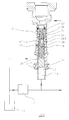
- Figure 2 is a sectional view of a pressure regulator in accordance with an embodiment of the present invention; and
- Figure 3 is a graph to illustrate pressure against engine speed for the pressure regulator shown in Figure 2 when employed in a fuel pump for use in an engine.
-
- Figure 2 illustrates a pressure regulator for use in regulating the outlet pressure of a
transfer pump 21 which is used to supply fuel to an inlet of a high pressure fuel pump (not shown) for supplying fuel to a common rail or a distributed pumping system. Thetransfer pump 21 is arranged to draw fuel from afuel reservoir 23 and supplies fuel at a relatively low pressure to the high pressure fuel pump. - The pressure regulator comprises a sleeve or
regulator housing 20 provided with abore 22 within which apiston member 24 is moveable. Thepiston member 24 is of generally cylindrical form, the diameter of thepiston member 24 and the diameter of thebore 22 being selected to ensure movement of thepiston member 24 within thebore 22 is guided. Thesleeve 20 is provided with an outlet opening 36 positioned such that, depending upon the position of thepiston member 24 within thebore 22, the outlet opening 36 is either fully obscured by the cylindrical outer surface of thepiston member 24, is partially obscured by the outer surface of thepiston member 24 or is fully open. The outlet opening 36 communicates with thefuel reservoir 23 so as to regulate the outlet pressure of thepump 21. - One end of the
piston member 24 defines a surface 24a which is exposed to fuel pressure at the outlet of thetransfer pump 21 in an inlet region orinlet chamber 31 defined by thebore 22. The pressure of fuel in theinlet region 31 determines the position of thepiston member 24 within thebore 22 and, hence, determines the rate of flow of fuel through the outlet opening 36. As fuel pressure within theinlet region 31 increases, thepiston member 24 gradually opens theoutlet opening 36 depending on fuel pressure within theinlet region 31, as described in further detail below. - The pressure regulator also includes a
spring assembly 25 including first andsecond springs spring assembly 25 being arranged to apply a biasing force to thepiston member 24 which opposes the force due to fuel pressure acting on thepiston member 24. Thespring assembly 25 also includes anabutment member 28 which is moveable within thebore 22 and is engageable with afirst adjustment member 34 in the form of a stop member upon movement of theabutment member 28 beyond a predetermined amount, as will be described in further detail hereinafter. Themoveable abutment member 28 includes an annular region 28a and is arranged between the first andsecond springs first spring 26 is in abutment with a first abutment surface defined by the annular region 28a of theabutment member 28 and one end of thesecond spring 30 is in abutment with an opposing abutment surface defined by the annular region 28a of theabutment member 28. The end of thesecond spring 30 remote from theabutment member 28 is in engagement with afurther adjustment member 32 provided with a through bore through which thestop 34 extends, theadjustment member 32 being in screw threaded engagement with thesleeve 20 so as to permit the position of theadjustment member 32 relative to thesleeve 20 to be varied. It will be appreciated that the pre-load of thespring assembly 25 can be adjusted by adjusting the position of theadjustment member 32 relative to thesleeve 20. Typically, thestop 34 and theadjustment member 32 take the form of adjustment screws. - The
abutment member 28 is provided with afirst drilling 27 in communication with asecond drilling 29 provided in thestop 34. The provision of thedrillings bore 22 within which thefirst spring 26 is arranged to be vented, thereby preventing thepiston member 24 becoming hydraulically locked within thesleeve 20. In addition, as a restricted flow of fuel is permitted through a relatively narrow clearance defined by thepiston member 24 and thebore 22, the provision of thedrillings piston member 24 and thebore 22, the dimensions of the clearance are such that movement of thepiston member 24 within thebore 22 is guided. - In use, prior to engine start up, the
abutment member 28 occupies a position in which it is spaced away from the surface 34a of thestop 34, the position of theadjustment member 32 relative to thesleeve 20 being selected so as to provide the desired pre-load of thespring assembly 25. Upon engine start up, as engine speed is increased, fuel pressure at the outlet of thetransfer pump 21, and hence fuel pressure in theinlet region 31, is also increased, thereby causing the force applied to the surface 24a of thepiston member 24 to be increased. During this first stage of operation, a point will be reached at which the force due to fuel pressure acting on the surface 24a of thepiston member 24 is sufficient to overcome the biasing force of thespring assembly 25 such that thepiston member 24 is caused to move so as to open, partially, theoutlet opening 36. Theoutlet opening 36 communicates with thefuel reservoir 23 such that fuel pressure at the outlet of thepump 21 is regulated, depending on the extent to which theoutlet opening 36 is uncovered by thepiston member 24. During this stage of operation, the amount by which thepiston member 24 is displaced as fuel pressure within theinlet region 31 increases will be determined by the spring characteristics of the first andsecond springs inlet region 31 increases, theoutlet opening 36 will be opened progressively from a fully obscured state, in which the outer surface of thepiston member 24 breaks communication completely (except for minimal fuel leakage) between theinlet region 31 and theoutlet opening 36, and a partially obscured state in which the outer surface of thepiston member 24 partially obscures theoutlet opening 36. - As engine speed increases further, fuel pressure at the outlet of the
pump 21 continues to increase. When fuel pressure within theinlet region 31 exceeds a predetermined amount, theabutment member 28 is urged into engagement with thestop 34. Upon engagement between theabutment member 28 and thestop 34, movement of theabutment member 28 is terminated and thesecond spring 30 becomes disabled such that, for a further increase in fuel pressure within theinlet region 31, only the spring characteristic of thefirst spring 26 will determine the rate at which displacement of thepiston member 24 varies with fuel pressure. It will therefore be appreciated that the rate at which displacement of thepiston member 24 varies with fuel pressure depends on whether theabutment member 28 is in engagement with thestop 34. Thus, at higher engine speeds, when fuel pressure at the outlet of thepump 21 is relatively high, the pressure regulator has a different pressure-speed regulating characteristic compared with that at lower engine speeds. - During the second stage of operation when the
second spring 30 is disabled, the extent to which theoutlet opening 36 is obscured will also vary progressively with increasing fuel pressure within theinlet region 31 from a state in which theoutlet opening 36 is partially obscured and a state in which theoutlet opening 36 is opened to a maximum extent. It will therefore be appreciated that during both the first stage of operation, when both the first and second spring forces act on thepiston member 24, and the second stage of operation, when only the first spring force acts on thepiston member 24, the extent to which theoutlet opening 36 is uncovered by thepiston member 24 will vary progressively as fuel pressure in theinlet region 31 increases, even though the rate of displacement of thepiston member 24 with fluid pressure will be different during the first and second stages. The pressure regulator is configured such that, during both the first and second stages of operation, there is an approximately linear relationship between the uncovered flow area presented by theoutlet opening 36 and fuel pressure in theinlet region 31. - In order to maintain control of pressure regulation, the characteristics of the first and second springs are preferably selected to ensure that, when fuel pressure within the
inlet region 31 reaches a maximum value for the particular pump/engine application and theoutlet opening 36 is opened to the maximum extent by the piston member 24 (i.e. the second stage of operation), thepiston member 24 is in a position in which theoutlet opening 36 is only partially obscured by the outer surface of thepiston member 24. - Figure 3 shows the relationship between the regulated pump outlet pressure (i.e. in the inlet region 31) and engine speed. Upon engine start up (engine speed A) to the point at which the engine reaches engine speed B, the force acting on the surface 24a of the
piston member 24 is insufficient to overcome the biasing force due to thespring assembly 25 such that the outlet opening 36 remains closed by thepiston member 24. Once the engine reaches engine speed B, the pressure of fuel at the outlet of thepump 21 is increased sufficiently to cause thepiston member 24 to move within thebore 22 so as to compress the first andsecond springs piston member 24 causing the outlet opening 36 to be partially opened, until the engine speed increases to engine speed C. The rate at which the pump outlet pressure increases with engine speed (i.e. the slope of the pressure-speed characteristic) between engine speeds B and C is governed by the spring characteristics of both the first andsecond springs - Once the engine speed is increased beyond engine speed C, the force due to fuel at the outlet of the pump acting on the surface 24a of the
piston member 24 is sufficient to cause theabutment member 28 to move into engagement with thestop 34, thereby terminating movement of theabutment member 28 and disabling thesecond spring 30. For engine speeds in excess of engine speed C, the relationship between pump outlet pressure and engine speed is therefore governed only by the spring characteristic of thefirst spring 26. - It will be appreciated that the engine speed C at which the
second spring 30 becomes disabled, and hence the engine speed C at which the slope of the pressure-engine speed characteristic of the pump is altered, is determined by the pre-set, fixed position of thestop 34 within thebore 22. Thus, by adjusting the position of thestop 34 relative to thebore 22 in thesleeve 20 prior to use of the pump, the required fuel pressure at which thesecond spring 30 becomes disabled can be pre-set to the desired value. The engine speed C at which the pressure-engine speed characteristic changes is therefore selected by adjusting the position of thestop 34 within thebore 22 prior to use of the pump. - The present invention provides the advantage that the pressure-engine speed characteristic of the pump can be adjusted by adjusting the position of the
stop 34 and theadjustment member 32, thereby allowing pump to pump variations to be compensated for. - The invention also provides the advantage that the pressure-engine speed characteristic of the pump can be tailored so as to ensure the required transfer pressure is achieved at the two speeds (e.g. speeds D and E in Figure 3) at which emission levels are measured for the purposes of regulatory approval. For a conventional pressure regulator, the rate of variation of transfer pressure with engine speed is substantially linear and so it is only possible to ensure the desired transfer pressure is achieved at one of the critical emissions speeds.
- The present invention is also advantageous in that the adjustable pressure regulator occupies a relatively small volume of space.
Claims (16)
- A pressure regulator for use in regulating the outlet pressure of a pump for use in an engine, the pressure regulator comprising a piston member (24) which is moveable within a bore (22) provided in a regulator housing (20) with respect to an outlet opening (36) under the influence of fluid pressure acting on the piston member (24) to control the degree by which the outlet opening (36) is obscured, and a biasing arrangement (25, 26, 28, 30) for applying a biasing force to the piston member (24) which opposes the pressure of fluid acting on the piston member (24), the biasing arrangement comprising a moveable abutment member (28) which is cooperable with a stop member (34) so as to terminate movement of the abutment member (28) when the abutment member moves into engagement with the stop member (34), in use, thereby to vary the rate at which the displacement of the piston member (24) varies with fluid pressure acting on the piston member (24), the stop member (34) having a pre-set fixed position relative to the regulator housing (22).
- The pressure regulator as claimed in Claim 1, wherein the stop member (34) takes the form of an adjustment screw.
- The pressure regulator as claimed in Claim 1 or Claim 2, wherein the biasing arrangement comprises first and second spring means (26, 30).
- The pressure regulator as claimed in Claim 3, wherein the first and second spring means take the form of compression springs (26, 30).
- The pressure regulator as claimed in Claim 4, wherein the moveable abutment member (28) includes an annular region (28a) defining first and second opposing abutment surfaces, the abutment member (28) being arranged such that one end of the first compression spring (26) is in abutment with the first abutment surface and one end of the second compression spring (30) is in abutment with the second abutment surface.
- The pressure regulator as claimed in any of Claims 1 to 5, wherein the stop member takes the form of an adjustment screw (34).
- The pressure regulator as claimed in any of Claims 1 to 6, further comprising an adjustment member (32) for adjusting the pre-load of the biasing arrangement.
- The pressure regulator as claimed in Claim 7, wherein the adjustment member (32) takes the form of a further adjustment screw having a position relative to the regulator housing (20) which is adjustable prior to use of the regulator to adjust the pre-load of the biasing arrangement.
- The pressure regulator as claimed in Claim 7 or Claim 8, wherein at least a part of the stop member (34) extends through a bore provided in the adjustment member (32).
- The pressure regulator as claimed in any of Claims 1 to 9, wherein the outlet (36) is provided in a side wall of the regulator housing (20).
- The pressure regulator as claimed in any of Claims 1 to 10, wherein the piston member (24) is shaped to cooperate with the outlet opening (36) to progressively open the outlet opening (36) depending upon the extent to which the piston member (24) is displaced.
- The pressure regulator as claimed in Claim 11, wherein the piston member (24) is of generally cylindrical form and has a generally cylindrical outer surface which cooperates with the outlet opening (36) to progressively vary the extent to which the outlet opening (36) is obscured, depending on the position of the piston member (24) within the bore (22).
- The pressure regulator as claimed in Claim 12, wherein the diameter of the piston member (24) and the diameter of the bore (22) are selected to ensure movement of the piston member (24) within the bore (22) is guided.
- A transfer pump (21) for use in supplying fuel to a high pressure pump for an engine, the transfer pump (21) comprising a pump outlet through which fuel is supplied at a pressure dependent upon engine speed to the high pressure pump, the transfer pump further comprising a pressure regulator as claimed in any of Claims 1 to 13 which is arranged to regulate the pressure of fuel delivered by the transfer pump, in use.
- The transfer pump as claimed in Claim 14, wherein the pressure regulator (21) of the transfer pump (21) comprises an inlet region (31) defined by the bore (22) within which the piston member (24) of the pressure regulator moves to vary the extent to which the outlet opening (36) is obscured, the pump outlet being arranged to deliver fuel to the inlet region (31) at a pressure dependent upon the engine speed.
- A fuel system for supplying fuel to an engine, the fuel system comprising a transfer pump (21) for delivering fuel at relatively low pressure to a high pressure fuel, the high pressure fuel pump being arranged to deliver fuel to the engine, the fuel system further comprising a pressure regulator as claimed in any of Claims 1 to 13 which is arranged to regulate the pressure of fuel delivered by the transfer pump to the high pressure pump, in use.
Applications Claiming Priority (2)
| Application Number | Priority Date | Filing Date | Title |
|---|---|---|---|
| GB0023242 | 2000-09-22 | ||
| GBGB0023242.1A GB0023242D0 (en) | 2000-09-22 | 2000-09-22 | Pressure regulator |
Publications (2)
| Publication Number | Publication Date |
|---|---|
| EP1191221A1 true EP1191221A1 (en) | 2002-03-27 |
| EP1191221B1 EP1191221B1 (en) | 2004-02-18 |
Family
ID=9899913
Family Applications (1)
| Application Number | Title | Priority Date | Filing Date |
|---|---|---|---|
| EP01308107A Expired - Lifetime EP1191221B1 (en) | 2000-09-22 | 2001-09-24 | Pressure regulator |
Country Status (4)
| Country | Link |
|---|---|
| US (2) | US6546913B2 (en) |
| EP (1) | EP1191221B1 (en) |
| DE (1) | DE60102048T2 (en) |
| GB (1) | GB0023242D0 (en) |
Cited By (1)
| Publication number | Priority date | Publication date | Assignee | Title |
|---|---|---|---|---|
| DE102007000104B4 (en) * | 2006-02-23 | 2011-06-09 | Denso Corporation, Kariya-City | regulator |
Families Citing this family (5)
| Publication number | Priority date | Publication date | Assignee | Title |
|---|---|---|---|---|
| GB0023242D0 (en) | 2000-09-22 | 2000-11-01 | Delphi Tech Inc | Pressure regulator |
| US7883073B2 (en) | 2008-01-15 | 2011-02-08 | Emerson Process Management Power And Water Solutions, Inc. | Methods and apparatus for adjusting a spring load in an actuator |
| US8517000B2 (en) * | 2008-09-18 | 2013-08-27 | Wayne Rowland | Fuel treatment device using heat and magnetic field |
| US8240291B2 (en) * | 2009-10-23 | 2012-08-14 | Caterpillar Inc. | Pressure relief valve |
| US8522751B2 (en) * | 2010-09-01 | 2013-09-03 | Honda Motor Co., Ltd. | Fuel pressure regulator for a motor vehicle |
Citations (7)
| Publication number | Priority date | Publication date | Assignee | Title |
|---|---|---|---|---|
| US4178137A (en) * | 1977-01-04 | 1979-12-11 | Lucas Industries Limited | Pressure regulator for a fluid pump |
| US4282843A (en) * | 1978-03-22 | 1981-08-11 | Lucas Industries Limited | Liquid fuel injection pump |
| US4393844A (en) * | 1979-07-06 | 1983-07-19 | Lucas Industries Limited | Liquid fuel pumping apparatus |
| US4421084A (en) * | 1978-02-21 | 1983-12-20 | Lucas Industries Limited | Fuel injection pumping apparatus |
| US4455126A (en) * | 1981-04-23 | 1984-06-19 | Lucas Industries Plc | Fuel pumping apparatus |
| WO1999030020A1 (en) * | 1997-12-12 | 1999-06-17 | Alliedsignal Inc. | Force balanced proportional bypass valve |
| CH690191A5 (en) | 1998-07-29 | 2000-05-31 | Beringer Hydraulik Ag | Hydraulic pressure limitation/safety valve has return spring of primary and counter spring parts, and hydraulic control piston between parts, pressed against captive spring when set control pressure is exceeded |
Family Cites Families (18)
| Publication number | Priority date | Publication date | Assignee | Title |
|---|---|---|---|---|
| US2518387A (en) * | 1944-11-03 | 1950-08-08 | Eaton Mfg Co | Relief valve |
| US2644480A (en) * | 1948-10-27 | 1953-07-07 | Clarence E Earle | Fluid valve |
| US3207140A (en) * | 1962-09-10 | 1965-09-21 | Hartford Machine Screw Co | Fuel pump |
| GB1026790A (en) * | 1964-01-09 | 1966-04-20 | Cav Ltd | Liquid fuel injection pumping apparatus for internal combustion engines |
| SE379843B (en) | 1973-08-28 | 1975-10-20 | L G Berg | |
| US4419054A (en) * | 1980-07-02 | 1983-12-06 | Lucas Industries Limited | Liquid fuel injection pumping apparatus |
| JPS58186165U (en) * | 1982-06-04 | 1983-12-10 | 日産自動車株式会社 | distribution type fuel injection pump |
| GB8300638D0 (en) * | 1983-01-11 | 1983-02-09 | Lucas Ind Plc | Fuel injection pumps |
| GB8332110D0 (en) * | 1983-12-01 | 1984-01-11 | Lucas Ind Plc | Fuel injection pumping apparatus |
| GB8406270D0 (en) * | 1984-03-09 | 1984-04-11 | Lucas Ind Plc | Fuel system |
| US5050637A (en) * | 1990-05-23 | 1991-09-24 | Kawasaki Jukogyo Kabushiki Kaisha | Relief valve |
| US5577533A (en) * | 1994-09-13 | 1996-11-26 | Cook, Jr.; Joseph S. | Flexured shaft poppet |
| US6125822A (en) * | 2000-02-04 | 2000-10-03 | Stanadyne Automotive Corp. | Two stage pressure relief valve |
| US6562502B2 (en) * | 2000-05-01 | 2003-05-13 | Delphi Technologies, Inc. | Fuel cell hot zone pressure regulator |
| GB0023242D0 (en) | 2000-09-22 | 2000-11-01 | Delphi Tech Inc | Pressure regulator |
| US6481418B1 (en) * | 2000-10-23 | 2002-11-19 | Delphi Technologies, Inc. | Fuel pressure regulator |
| US6382183B1 (en) * | 2000-11-09 | 2002-05-07 | Delphi Technologies, Inc. | Fuel system pressure regulator |
| US6422265B1 (en) * | 2000-12-15 | 2002-07-23 | Delphi Technologies, Inc. | Valve seat for fuel pressure regulator |
-
2000
- 2000-09-22 GB GBGB0023242.1A patent/GB0023242D0/en not_active Ceased
-
2001
- 2001-09-21 US US09/957,721 patent/US6546913B2/en not_active Expired - Lifetime
- 2001-09-24 DE DE60102048T patent/DE60102048T2/en not_active Expired - Lifetime
- 2001-09-24 EP EP01308107A patent/EP1191221B1/en not_active Expired - Lifetime
-
2002
- 2002-07-23 US US10/201,149 patent/US6892709B2/en not_active Expired - Fee Related
Patent Citations (7)
| Publication number | Priority date | Publication date | Assignee | Title |
|---|---|---|---|---|
| US4178137A (en) * | 1977-01-04 | 1979-12-11 | Lucas Industries Limited | Pressure regulator for a fluid pump |
| US4421084A (en) * | 1978-02-21 | 1983-12-20 | Lucas Industries Limited | Fuel injection pumping apparatus |
| US4282843A (en) * | 1978-03-22 | 1981-08-11 | Lucas Industries Limited | Liquid fuel injection pump |
| US4393844A (en) * | 1979-07-06 | 1983-07-19 | Lucas Industries Limited | Liquid fuel pumping apparatus |
| US4455126A (en) * | 1981-04-23 | 1984-06-19 | Lucas Industries Plc | Fuel pumping apparatus |
| WO1999030020A1 (en) * | 1997-12-12 | 1999-06-17 | Alliedsignal Inc. | Force balanced proportional bypass valve |
| CH690191A5 (en) | 1998-07-29 | 2000-05-31 | Beringer Hydraulik Ag | Hydraulic pressure limitation/safety valve has return spring of primary and counter spring parts, and hydraulic control piston between parts, pressed against captive spring when set control pressure is exceeded |
Cited By (1)
| Publication number | Priority date | Publication date | Assignee | Title |
|---|---|---|---|---|
| DE102007000104B4 (en) * | 2006-02-23 | 2011-06-09 | Denso Corporation, Kariya-City | regulator |
Also Published As
| Publication number | Publication date |
|---|---|
| US20020179064A1 (en) | 2002-12-05 |
| DE60102048T2 (en) | 2004-10-21 |
| US6892709B2 (en) | 2005-05-17 |
| US20020035985A1 (en) | 2002-03-28 |
| GB0023242D0 (en) | 2000-11-01 |
| DE60102048D1 (en) | 2004-03-25 |
| US6546913B2 (en) | 2003-04-15 |
| EP1191221B1 (en) | 2004-02-18 |
Similar Documents
| Publication | Publication Date | Title |
|---|---|---|
| EP1701074B1 (en) | Soft ventable relief valve | |
| US6220528B1 (en) | Fuel injector including an outer valve needle, and inner valve needle slidable within a bore formed in the outer valve needle | |
| US4530337A (en) | Fuel injection pump | |
| CN1089855C (en) | Fuel injection valve | |
| US5538187A (en) | Fuel injection device for internal combustion engines | |
| US20020014540A1 (en) | Fuel injector | |
| EP0943797A1 (en) | Fuel injector | |
| EP0890736B1 (en) | Injector | |
| US4201522A (en) | Boost-retarding device for electromagnetic plunger pump and the like | |
| GB2086473A (en) | Fuel injection valve for compression ignition engines | |
| JP2005532501A (en) | Relief valve | |
| US6546913B2 (en) | Pressure regulator | |
| US3945360A (en) | RPM Regulator for fuel injection pumps | |
| GB2318152A (en) | I.c. engine fuel-injection valve with controllable two-stage opening stroke | |
| US6053425A (en) | Injector | |
| US6269795B1 (en) | Fuel injection valve for internal combustion engines | |
| US4534332A (en) | Fuel injection pump for internal combustion engines with an adjustment of the instant of injection | |
| US4917306A (en) | Fuel injection nozzle | |
| GB2203795A (en) | I.C. engine fuel injection nozzle | |
| JPH07217552A (en) | Relief pressure regulator | |
| US6419164B1 (en) | Fuel injection valve for internal combustion engines | |
| GB2345518A (en) | Common rail pre-supply pump system with lubricating flow valve | |
| US5462252A (en) | Spill valve for a fuel pump | |
| EP1063418B1 (en) | Fuel injector | |
| GB2140081A (en) | Fuel injection nozzle |
Legal Events
| Date | Code | Title | Description |
|---|---|---|---|
| PUAI | Public reference made under article 153(3) epc to a published international application that has entered the european phase |
Free format text: ORIGINAL CODE: 0009012 |
|
| AK | Designated contracting states |
Kind code of ref document: A1 Designated state(s): AT BE CH CY DE DK ES FI FR GB GR IE IT LI LU MC NL PT SE TR |
|
| AX | Request for extension of the european patent |
Free format text: AL;LT;LV;MK;RO;SI |
|
| 17P | Request for examination filed |
Effective date: 20020715 |
|
| 17Q | First examination report despatched |
Effective date: 20020920 |
|
| AKX | Designation fees paid |
Free format text: DE ES FR GB IT |
|
| GRAP | Despatch of communication of intention to grant a patent |
Free format text: ORIGINAL CODE: EPIDOSNIGR1 |
|
| GRAS | Grant fee paid |
Free format text: ORIGINAL CODE: EPIDOSNIGR3 |
|
| GRAA | (expected) grant |
Free format text: ORIGINAL CODE: 0009210 |
|
| AK | Designated contracting states |
Kind code of ref document: B1 Designated state(s): DE ES FR GB IT |
|
| PG25 | Lapsed in a contracting state [announced via postgrant information from national office to epo] |
Ref country code: IT Free format text: LAPSE BECAUSE OF FAILURE TO SUBMIT A TRANSLATION OF THE DESCRIPTION OR TO PAY THE FEE WITHIN THE PRE;WARNING: LAPSES OF ITALIAN PATENTS WITH EFFECTIVE DATE BEFORE 2007 MAY HAVE OCCURRED AT ANY TIME BEFORE 2007. THE CORRECT EFFECTIVE DATE MAY BE DIFFERENT FROM THE ONE RECORDED.SCRIBED TIME-LIMIT Effective date: 20040218 |
|
| REG | Reference to a national code |
Ref country code: GB Ref legal event code: FG4D |
|
| REG | Reference to a national code |
Ref country code: IE Ref legal event code: FG4D |
|
| REF | Corresponds to: |
Ref document number: 60102048 Country of ref document: DE Date of ref document: 20040325 Kind code of ref document: P |
|
| PG25 | Lapsed in a contracting state [announced via postgrant information from national office to epo] |
Ref country code: ES Free format text: LAPSE BECAUSE OF FAILURE TO SUBMIT A TRANSLATION OF THE DESCRIPTION OR TO PAY THE FEE WITHIN THE PRESCRIBED TIME-LIMIT Effective date: 20040529 |
|
| ET | Fr: translation filed | ||
| PLBE | No opposition filed within time limit |
Free format text: ORIGINAL CODE: 0009261 |
|
| STAA | Information on the status of an ep patent application or granted ep patent |
Free format text: STATUS: NO OPPOSITION FILED WITHIN TIME LIMIT |
|
| 26N | No opposition filed |
Effective date: 20041119 |
|
| REG | Reference to a national code |
Ref country code: IE Ref legal event code: MM4A |
|
| PG25 | Lapsed in a contracting state [announced via postgrant information from national office to epo] |
Ref country code: GB Free format text: LAPSE BECAUSE OF NON-PAYMENT OF DUE FEES Effective date: 20050924 |
|
| GBPC | Gb: european patent ceased through non-payment of renewal fee |
Effective date: 20050924 |
|
| REG | Reference to a national code |
Ref country code: FR Ref legal event code: TP |
|
| REG | Reference to a national code |
Ref country code: FR Ref legal event code: TP Owner name: DELPHI INTERNATIONAL OPERATIONS LUXEMBOURG S.A, LU Effective date: 20140516 |
|
| REG | Reference to a national code |
Ref country code: DE Ref legal event code: R082 Ref document number: 60102048 Country of ref document: DE Representative=s name: MANITZ, FINSTERWALD & PARTNER GBR, DE |
|
| REG | Reference to a national code |
Ref country code: DE Ref legal event code: R082 Ref document number: 60102048 Country of ref document: DE Representative=s name: MANITZ, FINSTERWALD & PARTNER GBR, DE Effective date: 20140702 Ref country code: DE Ref legal event code: R081 Ref document number: 60102048 Country of ref document: DE Owner name: DELPHI INTERNATIONAL OPERATIONS LUXEMBOURG S.A, LU Free format text: FORMER OWNER: DELPHI TECHNOLOGIES HOLDING S.A.R.L., BASCHARAGE, LU Effective date: 20140702 |
|
| PGFP | Annual fee paid to national office [announced via postgrant information from national office to epo] |
Ref country code: FR Payment date: 20140917 Year of fee payment: 14 |
|
| PGFP | Annual fee paid to national office [announced via postgrant information from national office to epo] |
Ref country code: DE Payment date: 20140929 Year of fee payment: 14 |
|
| REG | Reference to a national code |
Ref country code: DE Ref legal event code: R119 Ref document number: 60102048 Country of ref document: DE |
|
| REG | Reference to a national code |
Ref country code: FR Ref legal event code: ST Effective date: 20160531 |
|
| PG25 | Lapsed in a contracting state [announced via postgrant information from national office to epo] |
Ref country code: DE Free format text: LAPSE BECAUSE OF NON-PAYMENT OF DUE FEES Effective date: 20160401 |
|
| PG25 | Lapsed in a contracting state [announced via postgrant information from national office to epo] |
Ref country code: FR Free format text: LAPSE BECAUSE OF NON-PAYMENT OF DUE FEES Effective date: 20150930 |