EP1191220A1 - A fuel injection valve - Google Patents
A fuel injection valve Download PDFInfo
- Publication number
- EP1191220A1 EP1191220A1 EP00120143A EP00120143A EP1191220A1 EP 1191220 A1 EP1191220 A1 EP 1191220A1 EP 00120143 A EP00120143 A EP 00120143A EP 00120143 A EP00120143 A EP 00120143A EP 1191220 A1 EP1191220 A1 EP 1191220A1
- Authority
- EP
- European Patent Office
- Prior art keywords
- valve
- sleeve
- fuel injection
- core
- injection valve
- Prior art date
- Legal status (The legal status is an assumption and is not a legal conclusion. Google has not performed a legal analysis and makes no representation as to the accuracy of the status listed.)
- Ceased
Links
Images



Classifications
-
- F—MECHANICAL ENGINEERING; LIGHTING; HEATING; WEAPONS; BLASTING
- F02—COMBUSTION ENGINES; HOT-GAS OR COMBUSTION-PRODUCT ENGINE PLANTS
- F02M—SUPPLYING COMBUSTION ENGINES IN GENERAL WITH COMBUSTIBLE MIXTURES OR CONSTITUENTS THEREOF
- F02M51/00—Fuel-injection apparatus characterised by being operated electrically
- F02M51/06—Injectors peculiar thereto with means directly operating the valve needle
- F02M51/061—Injectors peculiar thereto with means directly operating the valve needle using electromagnetic operating means
- F02M51/0625—Injectors peculiar thereto with means directly operating the valve needle using electromagnetic operating means characterised by arrangement of mobile armatures
- F02M51/0664—Injectors peculiar thereto with means directly operating the valve needle using electromagnetic operating means characterised by arrangement of mobile armatures having a cylindrically or partly cylindrically shaped armature, e.g. entering the winding; having a plate-shaped or undulated armature entering the winding
- F02M51/0671—Injectors peculiar thereto with means directly operating the valve needle using electromagnetic operating means characterised by arrangement of mobile armatures having a cylindrically or partly cylindrically shaped armature, e.g. entering the winding; having a plate-shaped or undulated armature entering the winding the armature having an elongated valve body attached thereto
-
- F—MECHANICAL ENGINEERING; LIGHTING; HEATING; WEAPONS; BLASTING
- F02—COMBUSTION ENGINES; HOT-GAS OR COMBUSTION-PRODUCT ENGINE PLANTS
- F02M—SUPPLYING COMBUSTION ENGINES IN GENERAL WITH COMBUSTIBLE MIXTURES OR CONSTITUENTS THEREOF
- F02M51/00—Fuel-injection apparatus characterised by being operated electrically
- F02M51/06—Injectors peculiar thereto with means directly operating the valve needle
- F02M51/061—Injectors peculiar thereto with means directly operating the valve needle using electromagnetic operating means
-
- F—MECHANICAL ENGINEERING; LIGHTING; HEATING; WEAPONS; BLASTING
- F02—COMBUSTION ENGINES; HOT-GAS OR COMBUSTION-PRODUCT ENGINE PLANTS
- F02M—SUPPLYING COMBUSTION ENGINES IN GENERAL WITH COMBUSTIBLE MIXTURES OR CONSTITUENTS THEREOF
- F02M51/00—Fuel-injection apparatus characterised by being operated electrically
- F02M51/06—Injectors peculiar thereto with means directly operating the valve needle
- F02M51/061—Injectors peculiar thereto with means directly operating the valve needle using electromagnetic operating means
- F02M51/0614—Injectors peculiar thereto with means directly operating the valve needle using electromagnetic operating means characterised by arrangement of electromagnets or fixed armature
-
- F—MECHANICAL ENGINEERING; LIGHTING; HEATING; WEAPONS; BLASTING
- F02—COMBUSTION ENGINES; HOT-GAS OR COMBUSTION-PRODUCT ENGINE PLANTS
- F02M—SUPPLYING COMBUSTION ENGINES IN GENERAL WITH COMBUSTIBLE MIXTURES OR CONSTITUENTS THEREOF
- F02M61/00—Fuel-injectors not provided for in groups F02M39/00 - F02M57/00 or F02M67/00
- F02M61/16—Details not provided for in, or of interest apart from, the apparatus of groups F02M61/02 - F02M61/14
- F02M61/168—Assembling; Disassembling; Manufacturing; Adjusting
Definitions
- This invention relates to a fuel injection valve mainly used in an engine for vehicle.
- Fig. 7 is a sectional side view showing a conventional fuel injection valve disclosed in, for example, the Unexamined Japanese Patent Application Publication No. Hei 9-324722.
- numeral 31 is a body
- numeral 32 is a hollow cylindrical-shaped sleeve welded after a press fit in the top end of the body 31, and in the upper half of the sleeve 32, the bottom of a tubular core 33 made of magnetic materials is welded after a press fit.
- Numeral 34 is a bobbin
- numeral 35 is a solenoid coil wound on the bobbin 34
- numeral 36 is a shaft-shaped valve
- numeral 37 is an armature.
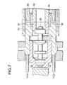
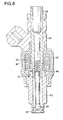
- Fig. 8 is a sectional side view showing a conventional injection valve disclosed in the Japanese Patent No. 2774153.
- numeral 38 is a core
- numeral 39 is an electromagnetic coil
- numeral 40 is a case
- numeral 41 is an armature
- numerals 42 and 43 are valve bodies
- numeral 44 is a valve seat
- numeral 45 is a valve element
- numeral 46 is a sleeve which has a cylinder portion formed in two steps and is a structure in which a stopper is not placed, and the sleeve 46 is formed in double cylinder shape.
- a sectional area of a portion along the core of the sleeve was not controlled and a section thickness of the sleeve was determined in consideration of only the structural strength of the sleeve. Also, the sectional area of the portion along the core of the sleeve is obviously more than or equal to 1/2 of the sectional area of the core.
- the sleeve was manufactured by cutting.
- the conventional fuel injection valves are constructed as described above and in the example shown in the Unexamined Japanese Patent Application Publication No. Hei 9-324722, the sleeve is formed in a hollow cylindrical shape, so that an axial length of the armature becomes long and the armature weight becomes heavy.
- the armature operates under high fuel pressure, so that a large electromagnetic attraction force is required and a side area of the armature needs to be increased, but a length of the armature needs to be lengthened in the case that sleeve is a hollow cylindrical shape, so that the armature weight becomes heavier.
- An increase in the armature weight reduces a response of a needle valve and it becomes difficult to ensure a wide flow control range necessary to the fuel injection valve for cylinder injection.
- an increase in the needle valve weight increases the occurrence of sound caused by a collision between the end surface of the armature and the end surface of the core and between the top end of the needle valve and the valve seat in the case of opening and closing the needle valve, and this adversely affects noise of a car.
- the sleeve 46 with the cylinder portion formed in two steps has not such a problem described above, but a large inner diameter portion of the sleeve 46 is in contact with an outer diameter portion of the valve body 43, so that a magnetic path detours and the energy loss due to an increase in reluctance occurs. Also, in the lower side of Fig. 8 from the large inner diameter portion of the sleeve 46, the case 40 is constructed so as to make contact with the outside of the valve body 42, so that the outer diameter of this portion increases.
- an air gap which is a gap between the core and the armature cannot be adjusted, and open time and close time of a solenoid valve cannot be properly adjusted.
- the amount equivalent to this air gap is adjusted by a film thickness of surface treatment of the core and the armature, but a thickness setting range of the film thickness is narrow, and the film thickness changes with time due to wear caused by the collision between the core and the armature.
- the inclination becomes large according to squareness of the core end surface, so that a flow passage sectional area between the valve seat and the top end of the needle valve becomes non-uniform, with the result that spray shapes of fuel vary with products.
- the sleeve is conventionally manufactured by cutting processing, there was a problem that it is difficult to make the section thickness to 0.5 mm or less in case that deformation in the processing intends to be not caused and the section thickness becomes thick and thus an outer diameter of a product increases.
- the invention is implemented to solve such problems, and it is an object of the invention to reduce a weight of a valve by shortening a length of an armature and increase control accuracy and a control range of a fuel flow by an improvement in response and further decrease operating noise.
- a fuel injection valve comprises a valve body coupled to a valve holder, a valve seat which is provided in this valve body and has an orifice, a valve element for separably contacting with this valve seat to open or close the orifice, an armature integrally formed with this valve element, and a coil for forming a magnetic circuit by this armature, a core and a yoke, and further step portions are provided in the core and the valve holder and an L-shaped sleeve fitted in these step portions is provided.
- a stopper is provided between the valve holder and the valve body.
- a sectional area of a portion along the core of the sleeve is less than or equal to 1/2 of a sectional area of the core.
- a rib for structural reinforcement is provided in a corner portion of the L shape of the sleeve.
- the sleeve is formed of a non-magnetic material with an electrical resistivity of 70 ⁇ ⁇ ⁇ cm or more and a permeability of 20 ⁇ 10 -7 h/m or less at 23 °C.
- the sleeve is manufactured of a plate material by plastic deformation.
- the sleeve is manufactured by metal injection molding.
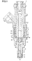
- Fig. 1 is a sectional side view showing a fuel injection valve according to a first embodiment of the invention.
- numeral 1 is a fuel injection valve for cylinder injection
- numeral 2 is a solenoid
- numeral 3 is a yoke
- numeral 4 is a core
- numeral 5 is a coil assembly
- numeral 6 is a coil
- numeral 7 is a bobbin
- numeral 8 is an armature
- numeral 9 is a valve unit and this valve unit 9 is coupled to one end of a valve holder 10 by means such as welding.
- the valve unit 9 comprises a hollow cylindrical-shaped valve body 11 with an outer diameter portion formed in two steps, a valve seat 13 which is fixed in the top of a center hole within the valve body 11 and has an orifice 12, a swirler 14 which is placed between the valve seat 13 and the valve body 11 and applies a swing flow to injection fuel, and a needle valve (valve element) 15 which is a valve mechanism for separably contacting with the valve seat 13 by the solenoid 2 to open or close the orifice 12.
- a sleeve 16 made of metal is placed between the core 4 and the valve holder 10, and the sleeve 16 is respectively coupled to the core 4 and the valve holder 10 by means such as welding, and this coupling means functions as sealing of internal fuel.
- the sleeve 16 is axially connected to the core 4 at a step portion 4A of a large diameter portion 4b and a small diameter portion 4c of the core 4, and an axial position of the core 4 is determined.
- a sectional shape of the sleeve 16 is formed in an L shape, and when an area in which the armature 8 is opposite to an inner circumference of the valve holder 10 intends to be secured, a portion in which an outer circumference of the armature 8 is opposite to an inner circumference of the sleeve 16 is axially short, so that a length of the armature 8 can be relatively shortened.
- an area of a magnetic path 4Q of the inner diameter side of the coil 6 which is the most convergence portion of the magnetic flux can be increased and a large electromagnetic attraction force is obtained.
- Fig. 3 is a sectional side view showing a fuel injection valve according to a second embodiment of the invention.
- a stopper 17 is disposed between the valve holder 10 and the valve body 11.
- a step portion 15A of the needle valve 15 makes contact with the stopper 17 and an angle of inclination in an opening state of the needle valve 15 can be determined, so that the inclined angle of the needle valve 15 to the valve seat 13 is small and variations in spray shape with products decreases.
- an adjustment margin of a distance (air gap) between a core end surface 4B and an armature end surface 8A in the case of opening the valve can be largely provided, so that a response of the needle valve 15 can be optimally adjusted and even in case of changing use conditions of the fuel injection valve (for example, fuel pressure), provisions can be made by only changing a design value of the air gap without a change in structure.
- the air gap (between 8A and 4B) could be adjusted, and the optimal setting of time for opening and closing the valve could be made. Accordingly, the control range of the injection fuel quantity could be easily increased.
- a sectional area of a portion along the core 4 of the sleeve 16 is less than or equal to 1/2 of a sectional area of the core 4.
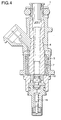
- Fig. 4 is a sectional side view showing a fuel injection valve according to a fourth embodiment of the invention.
- the sleeve 16 may be processed and manufactured of a plate material by plastic deformation. As a result of this, manufacturing costs of the sleeve 16 is reduced, and further the plate material is used, so that a section thickness can be made thinner than that of a cut product as shown in Fig. 4, and the ratio of the sectional area of the sleeve 16 to the sectional area of the core 4 can be decreased, so that the response of the needle valve 15 can be sped up.
- Fig. 5 is a sectional side view showing a fuel injection valve according to a fifth embodiment of the invention, and in the embodiment, the sleeve 16 is processed and manufactured of a plate material by plastic deformation and further a rib (stepped portion) 16a for structural reinforcement is provided in a corner portion of the L-shaped sleeve 16. Then, the rib 16a is provided in only all the circumference or a partially circumferential range of the sleeve 16. An example of providing the rib 16a in only the partially circumferential range is shown in Fig. 5. By the formation of such a shape, a strength (stiffness) increases compared with the L-shaped sleeve 16.
- the rib 16a for structural reinforcement is provided in a portion of the sleeve 16 of sheet metal, so that structural stability of the sleeve 16 was improved, and a margin (reliability) for preventing poor fuel sealing due to a change in performance and breakage of coupled portions was improved in relation to deformation in the case of using high fuel pressure or deformation in the case of manufacturing by assembly.
- Fig. 6 is a sectional side view showing a fuel injection valve according to a sixth embodiment of the invention, and it is constructed so that a step portion 4B is provided in the core 4 and a core outer diameter d 4 of this portion is made smaller than C 4 and a distance L between a terminal 18 and a shaft center of the fuel injection valve is reduced compared with the embodiments described above.
- a yoke inner diameter D 3 also becomes small, so that a yoke outer diameter C 3 also becomes small and a size of the fuel injection valve can be reduced.
- a winding position moves to the shaft center side of the fuel injection valve by thinning a section thickness of the sleeve 16 compared with the first to fourth embodiments, so that provisions can be made for a reduction in the yoke inner diameter D 3 .
- a gap 4C occurs and a magnetic path by the core 4 decreases . That is, a problem that a magnetic path sectional area of a core neck portion 4D becomes smaller than that of an air gap portion to reduce the number of magnetic fluxes arises.
- a rod 19 of a magnetic material the magnetic path sectional area is ensured using the rod 19 as a parallel magnetic path and a magnetic performance reduction can be avoided,
- a non-magnetic material with an electrical resistivity of 70 ⁇ ⁇ ⁇ cm or more and a permeability of 20 ⁇ 10 -7 h/m or less at a sleeve temperature of 23 °C may be used as material of the sleeve 16.
- the response delay of magnetism due to the eddy current occurring in the sleeve 16 can be made within tolerance limits, and response time of the needle valve 15 becomes fast and the control range of the injection fuel quantity can be increased.
- the sleeve 16 by metal injection molding, cost reduction and accuracy securement can be implemented.
- the fuel injection valve comprises a valve body coupled to a valve holder, a valve seat which is provided in this valve body and has an orifice, a valve element for separably contacting with this valve seat to open or close the orifice, an armature integrally formed with this valve element, and a coil for forming a magnetic circuit by this armature, a core and a yoke, and further step portions are provided in the core and the valve holder and an L-shaped sleeve fitted in these step portions is provided, so that a response by weight reduction of the armature can be improved and accordingly a control range of an injection fuel quantity can be increased.
- a stopper is provided between the valve holder and the valve body, so that an air gap can be adjusted and the optimum setting of time for opening and closing a valve can be made.
- a sectional area of a portion along the core of the sleeve is less than or equal to 1/2 of a sectional area of the core, so that a magnetic delay due to an eddy current decreases and the control range of the injection fuel quantity can be increased.
- a rib for structural reinforcement is provided in a corner portion of the L shape of the sleeve, so that structural stability of the sleeve can be improved.
- the sleeve is formed of a non-magnetic material with an electrical resistivity of 70 ⁇ ⁇ ⁇ cm or more and a permeability of 20 ⁇ 10 -7 h/m or less at 23 °C, so that the magnetic delay due to the eddy current decreases and also, response time of the valve element becomes fast and the control range of the injection fuel quantity can be increased.
- the sleeve is manufactured of a plate material by plastic deformation, so that thickness thinning impossible for cutting processing is implemented and an improvement in response by a reduction in a sectional area of a magnetic path can be implemented at a low cost.
- the sleeve is manufactured by metal injection molding, so that accuracy close to the cutting processing can be ensured and manufacturing costs can be reduced.
Landscapes
- Engineering & Computer Science (AREA)
- Physics & Mathematics (AREA)
- Electromagnetism (AREA)
- Chemical & Material Sciences (AREA)
- Combustion & Propulsion (AREA)
- Mechanical Engineering (AREA)
- General Engineering & Computer Science (AREA)
- Manufacturing & Machinery (AREA)
- Fuel-Injection Apparatus (AREA)
- Magnetically Actuated Valves (AREA)
Abstract
Description
- This invention relates to a fuel injection valve mainly used in an engine for vehicle.
- Fig. 7 is a sectional side view showing a conventional fuel injection valve disclosed in, for example, the Unexamined Japanese Patent Application Publication No. Hei 9-324722. In Fig. 7,
numeral 31 is a body, andnumeral 32 is a hollow cylindrical-shaped sleeve welded after a press fit in the top end of thebody 31, and in the upper half of thesleeve 32, the bottom of atubular core 33 made of magnetic materials is welded after a press fit. Numeral 34 is a bobbin, andnumeral 35 is a solenoid coil wound on thebobbin 34, andnumeral 36 is a shaft-shaped valve, andnumeral 37 is an armature. - Further, Fig. 8 is a sectional side view showing a conventional injection valve disclosed in the Japanese Patent No. 2774153. In Fig. 8,
numeral 38 is a core, andnumeral 39 is an electromagnetic coil, andnumeral 40 is a case, andnumeral 41 is an armature, andnumerals numeral 44 is a valve seat, andnumeral 45 is a valve element, andnumeral 46 is a sleeve which has a cylinder portion formed in two steps and is a structure in which a stopper is not placed, and thesleeve 46 is formed in double cylinder shape. - In the conventional examples described above, for both the examples, a sectional area of a portion along the core of the sleeve was not controlled and a section thickness of the sleeve was determined in consideration of only the structural strength of the sleeve. Also, the sectional area of the portion along the core of the sleeve is obviously more than or equal to 1/2 of the sectional area of the core.
- Further, for both the examples, the sleeve was manufactured by cutting.
- The conventional fuel injection valves are constructed as described above and in the example shown in the Unexamined Japanese Patent Application Publication No. Hei 9-324722, the sleeve is formed in a hollow cylindrical shape, so that an axial length of the armature becomes long and the armature weight becomes heavy. Particularly in the case of a fuel injection valve for cylinder injection, the armature operates under high fuel pressure, so that a large electromagnetic attraction force is required and a side area of the armature needs to be increased, but a length of the armature needs to be lengthened in the case that sleeve is a hollow cylindrical shape, so that the armature weight becomes heavier.
- An increase in the armature weight reduces a response of a needle valve and it becomes difficult to ensure a wide flow control range necessary to the fuel injection valve for cylinder injection.
- Also, an increase in the needle valve weight increases the occurrence of sound caused by a collision between the end surface of the armature and the end surface of the core and between the top end of the needle valve and the valve seat in the case of opening and closing the needle valve, and this adversely affects noise of a car.
- Also, in the Japanese Patent No. 2774153, the
sleeve 46 with the cylinder portion formed in two steps has not such a problem described above, but a large inner diameter portion of thesleeve 46 is in contact with an outer diameter portion of thevalve body 43, so that a magnetic path detours and the energy loss due to an increase in reluctance occurs. Also, in the lower side of Fig. 8 from the large inner diameter portion of thesleeve 46, thecase 40 is constructed so as to make contact with the outside of thevalve body 42, so that the outer diameter of this portion increases. - Further, since there is no stopper, an air gap which is a gap between the core and the armature cannot be adjusted, and open time and close time of a solenoid valve cannot be properly adjusted. In a conventional method, the amount equivalent to this air gap is adjusted by a film thickness of surface treatment of the core and the armature, but a thickness setting range of the film thickness is narrow, and the film thickness changes with time due to wear caused by the collision between the core and the armature.
- Furthermore, in the needle valve when opening the valve, the inclination becomes large according to squareness of the core end surface, so that a flow passage sectional area between the valve seat and the top end of the needle valve becomes non-uniform, with the result that spray shapes of fuel vary with products.
- Also, there was a problem that a sectional area of a portion along a magnetic path of the sleeve in which an eddy current occurs is large and the occurrence of the eddy current is large and the cost increases.
- Further, since the sleeve is conventionally manufactured by cutting processing, there was a problem that it is difficult to make the section thickness to 0.5 mm or less in case that deformation in the processing intends to be not caused and the section thickness becomes thick and thus an outer diameter of a product increases.
- The invention is implemented to solve such problems, and it is an object of the invention to reduce a weight of a valve by shortening a length of an armature and increase control accuracy and a control range of a fuel flow by an improvement in response and further decrease operating noise.
- A fuel injection valve according to
aspect 1 of the invention comprises a valve body coupled to a valve holder, a valve seat which is provided in this valve body and has an orifice, a valve element for separably contacting with this valve seat to open or close the orifice, an armature integrally formed with this valve element, and a coil for forming a magnetic circuit by this armature, a core and a yoke, and further step portions are provided in the core and the valve holder and an L-shaped sleeve fitted in these step portions is provided. - In the fuel injection valve according to
aspect 2 of the invention, a stopper is provided between the valve holder and the valve body. - In the fuel injection valve according to
aspect 3 of the invention, a sectional area of a portion along the core of the sleeve is less than or equal to 1/2 of a sectional area of the core. - In the fuel injection valve according to
aspect 4 of the invention, a rib for structural reinforcement is provided in a corner portion of the L shape of the sleeve. - In the fuel injection valve according to
aspect 5 of the invention, the sleeve is formed of a non-magnetic material with an electrical resistivity of 70 µ Ω · cm or more and a permeability of 20×10-7 h/m or less at 23 °C. - In the fuel injection valve according to
aspect 6 of the invention, the sleeve is manufactured of a plate material by plastic deformation. - In the fuel injection valve according to
aspect 7 of the invention, the sleeve is manufactured by metal injection molding. -
- Fig. 1 is a sectional side view showing a fuel injection valve according to a first embodiment of this invention;
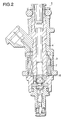
- Fig. 2 is a sectional side view illustrating the fuel injection valve according to the first embodiment of the invention;
- Fig. 3 is a sectional side view showing a fuel injection valve according to a second embodiment of the invention;
- Fig. 4 is a sectional side view showing a fuel injection valve according to a fourth embodiment of the invention;
- Fig. 5 is a sectional side view showing a fuel injection valve according to a fifth embodiment of the invention;
- Fig. 6 is a sectional side view showing a fuel injection valve according to a sixth embodiment of the invention;
- Fig. 7 is a sectional side view showing a conventional fuel injection valve; and
- Fig. 8 is a sectional side view showing a conventional fuel injection valve.
-
- Fig. 1 is a sectional side view showing a fuel injection valve according to a first embodiment of the invention. In Fig. 1,
numeral 1 is a fuel injection valve for cylinder injection, andnumeral 2 is a solenoid, andnumeral 3 is a yoke, andnumeral 4 is a core, andnumeral 5 is a coil assembly, andnumeral 6 is a coil, andnumeral 7 is a bobbin, andnumeral 8 is an armature, andnumeral 9 is a valve unit and thisvalve unit 9 is coupled to one end of avalve holder 10 by means such as welding. - The
valve unit 9 comprises a hollow cylindrical-shaped valve body 11 with an outer diameter portion formed in two steps, avalve seat 13 which is fixed in the top of a center hole within thevalve body 11 and has anorifice 12, aswirler 14 which is placed between thevalve seat 13 and thevalve body 11 and applies a swing flow to injection fuel, and a needle valve (valve element) 15 which is a valve mechanism for separably contacting with thevalve seat 13 by thesolenoid 2 to open or close theorifice 12. - In
solenoid 2, asleeve 16 made of metal is placed between thecore 4 and thevalve holder 10, and thesleeve 16 is respectively coupled to thecore 4 and thevalve holder 10 by means such as welding, and this coupling means functions as sealing of internal fuel. Thesleeve 16 is axially connected to thecore 4 at astep portion 4A of alarge diameter portion 4b and a small diameter portion 4c of thecore 4, and an axial position of thecore 4 is determined. - Next, operations will be described. When the
coil 6 is energized, a magnetic flux occurs in a magnetic circuit formed by thearmature 8, thecore 4 and theyoke 3, and thearmature 8 is attracted to the side of thecore 4, and when theneedle valve 15 integrally formed with thearmature 8 breaks contact with thevalve seat 13 to form a gap, fuel of high pressure flows from thevalve body 11 into theorifice 12 of thevalve seat 13 and is injected from the top outlet of theorifice 12 into a combustion chamber of an internal combustion engine. - In the invention, a sectional shape of the
sleeve 16 is formed in an L shape, and when an area in which thearmature 8 is opposite to an inner circumference of thevalve holder 10 intends to be secured, a portion in which an outer circumference of thearmature 8 is opposite to an inner circumference of thesleeve 16 is axially short, so that a length of thearmature 8 can be relatively shortened. - Also, by providing the
large diameter portion 4b in thecore 4, an area of amagnetic path 4Q of the inner diameter side of thecoil 6 which is the most convergence portion of the magnetic flux can be increased and a large electromagnetic attraction force is obtained. - That is, in the case of a straight shape of the small diameter portion 4c as shown in Fig. 2. without providing the large diameter portion in the
core 4, the magnetic path area of the inner diameter side of thecoil 6 becomes narrow and there is a disadvantage in an attraction force. On the contrary, it is contemplated to increase the number of windings of thecoil 6 to strengthen the attraction force by the decrease in the diameter of thecore 4, but the increase in the number of windings of the coil delays responses of a rise and a fall in the attraction force, so that a response of theneedle valve 15 is delayed. - By the construction as described above, a response by weight reduction of the
armature 8 is improved and accordingly a control range of an injection fuel quantity is increased.
Further, by the weight reduction of thearmature 8, wear in the valve is reduced and accordingly life is increased; and also operating noise is reduced and accordingly driverability of a car can be improved. - Fig. 3 is a sectional side view showing a fuel injection valve according to a second embodiment of the invention. In the embodiment, a
stopper 17 is disposed between thevalve holder 10 and thevalve body 11. When theneedle valve 15 is opened, astep portion 15A of theneedle valve 15 makes contact with thestopper 17 and an angle of inclination in an opening state of theneedle valve 15 can be determined, so that the inclined angle of theneedle valve 15 to thevalve seat 13 is small and variations in spray shape with products decreases. - Also, by properly selecting a thickness of the
stopper 17, an adjustment margin of a distance (air gap) between acore end surface 4B and anarmature end surface 8A in the case of opening the valve can be largely provided, so that a response of theneedle valve 15 can be optimally adjusted and even in case of changing use conditions of the fuel injection valve (for example, fuel pressure), provisions can be made by only changing a design value of the air gap without a change in structure. - By the construction as described above, the air gap (between 8A and 4B) could be adjusted, and the optimal setting of time for opening and closing the valve could be made. Accordingly, the control range of the injection fuel quantity could be easily increased.
- Also, an inclination in the case of opening the
needle valve 15 became small and non-uniformity in flow near the fuel outlet was decreased and accordingly, product variations in the injection fuel quantity and the spray shape were reduced. - Further, it may be constructed so that a sectional area of a portion along the
core 4 of thesleeve 16 is less than or equal to 1/2 of a sectional area of thecore 4. As a result of this, a magnetic delay due to an eddy current decreases and. response time of theneedle valve 15 can be sped up, so that the control range of the injection fuel quantity can be increased. - That is, in Fig. 3, in case where C4 is a core outer diameter and D4 is a core inner diameter and C16 is a sleeve outer diameter and D16 is a sleeve inner diameter and S4 is a core sectional area and S16 is a sleeve sectional area, S4= π/4(C4 2-D4 2) and S16=π/4 (C16 2-D16 2) and here, it is constructed so that the ratio between the sectional areas is S16/S4≦1/2.
- Fig. 4 is a sectional side view showing a fuel injection valve according to a fourth embodiment of the invention. In Fig. 4, the
sleeve 16 may be processed and manufactured of a plate material by plastic deformation. As a result of this, manufacturing costs of thesleeve 16 is reduced, and further the plate material is used, so that a section thickness can be made thinner than that of a cut product as shown in Fig. 4, and the ratio of the sectional area of thesleeve 16 to the sectional area of thecore 4 can be decreased, so that the response of theneedle valve 15 can be sped up. - Fig. 5 is a sectional side view showing a fuel injection valve according to a fifth embodiment of the invention, and in the embodiment, the
sleeve 16 is processed and manufactured of a plate material by plastic deformation and further a rib (stepped portion) 16a for structural reinforcement is provided in a corner portion of the L-shapedsleeve 16. Then, therib 16a is provided in only all the circumference or a partially circumferential range of thesleeve 16. An example of providing therib 16a in only the partially circumferential range is shown in Fig. 5. By the formation of such a shape, a strength (stiffness) increases compared with the L-shapedsleeve 16. - As described above, the
rib 16a for structural reinforcement is provided in a portion of thesleeve 16 of sheet metal, so that structural stability of thesleeve 16 was improved, and a margin (reliability) for preventing poor fuel sealing due to a change in performance and breakage of coupled portions was improved in relation to deformation in the case of using high fuel pressure or deformation in the case of manufacturing by assembly. - Also, by using the
sleeve 16 of sheet metal, a radial reduction in internal dimension of the fuel injection valve was implemented and a size of the fuel injection valve was reduced, so that engine mountability necessary for a cylinder injection valve was improved. - Fig. 6 is a sectional side view showing a fuel injection valve according to a sixth embodiment of the invention, and it is constructed so that a
step portion 4B is provided in thecore 4 and a core outer diameter d4 of this portion is made smaller than C4 and a distance L between a terminal 18 and a shaft center of the fuel injection valve is reduced compared with the embodiments described above. As a result of this, a yoke inner diameter D3 also becomes small, so that a yoke outer diameter C3 also becomes small and a size of the fuel injection valve can be reduced. - Incidentally, for the
coil 6, a winding position moves to the shaft center side of the fuel injection valve by thinning a section thickness of thesleeve 16 compared with the first to fourth embodiments, so that provisions can be made for a reduction in the yoke inner diameter D3. - Also, by providing the
step portion 4B, agap 4C occurs and a magnetic path by thecore 4 decreases . That is, a problem that a magnetic path sectional area of acore neck portion 4D becomes smaller than that of an air gap portion to reduce the number of magnetic fluxes arises. Thus, by forming arod 19 of a magnetic material, the magnetic path sectional area is ensured using therod 19 as a parallel magnetic path and a magnetic performance reduction can be avoided, - Also, as material of the
sleeve 16, a non-magnetic material with an electrical resistivity of 70 µ Ω · cm or more and a permeability of 20×10-7 h/m or less at a sleeve temperature of 23 °C may be used. As a result of this, the response delay of magnetism due to the eddy current occurring in thesleeve 16 can be made within tolerance limits, and response time of theneedle valve 15 becomes fast and the control range of the injection fuel quantity can be increased. - Further, by manufacturing the
sleeve 16 by metal injection molding, cost reduction and accuracy securement can be implemented. - According to a fuel injection valve of
aspect 1 of the invention, the fuel injection valve comprises a valve body coupled to a valve holder, a valve seat which is provided in this valve body and has an orifice, a valve element for separably contacting with this valve seat to open or close the orifice, an armature integrally formed with this valve element, and a coil for forming a magnetic circuit by this armature, a core and a yoke, and further step portions are provided in the core and the valve holder and an L-shaped sleeve fitted in these step portions is provided, so that a response by weight reduction of the armature can be improved and accordingly a control range of an injection fuel quantity can be increased. - According to the fuel injection valve of
aspect 2 of the invention, a stopper is provided between the valve holder and the valve body, so that an air gap can be adjusted and the optimum setting of time for opening and closing a valve can be made. - According to the fuel injection valve of
aspect 3 of the invention, a sectional area of a portion along the core of the sleeve is less than or equal to 1/2 of a sectional area of the core, so that a magnetic delay due to an eddy current decreases and the control range of the injection fuel quantity can be increased. - According to the fuel injection valve of
aspect 4 of the invention, a rib for structural reinforcement is provided in a corner portion of the L shape of the sleeve, so that structural stability of the sleeve can be improved. - According to the fuel injection valve of
aspect 5 of the invention, the sleeve is formed of a non-magnetic material with an electrical resistivity of 70 µ Ω · cm or more and a permeability of 20×10-7 h/m or less at 23 °C, so that the magnetic delay due to the eddy current decreases and also, response time of the valve element becomes fast and the control range of the injection fuel quantity can be increased. - According to the fuel injection valve of
aspect 6 of the invention, the sleeve is manufactured of a plate material by plastic deformation, so that thickness thinning impossible for cutting processing is implemented and an improvement in response by a reduction in a sectional area of a magnetic path can be implemented at a low cost. - According to the fuel injection valve of
aspect 7 of the invention, the sleeve is manufactured by metal injection molding, so that accuracy close to the cutting processing can be ensured and manufacturing costs can be reduced.
Claims (7)
- A fuel injection valve comprising:a valve body coupled to a valve holder,a valve seat which is provided in said valve body and has an orifice,a valve element for separably contacting with said valve seat to open or close the orifice,an armature integrally formed with said valve element, anda coil for forming a magnetic circuit by said armature, a core and a yoke, whereinstep portions are provided in said core and said valve holder, andan L-shaped sleeve fitted in said step portions is provided.
- The fuel injection valve as defined in claim 1, further comprising:a stopper between said valve holder and said valve body.
- The fuel injection valve as defined in claim 1 or 2, whereina sectional area of a portion along said core of said sleeve is less than or equal to 1/2 of a sectional area of said core.
- The fuel injection valve as defined in one of claims 1 to 3, further comprising:a rib for structural reinforcement in a corner portion of the L shape of said sleeve.
- The fuel injection valve as defined in one of claims 1 to 4, wherein
said sleeve is formed of a non-magnetic material with an electrical resistivity of 70 µ Ω · cm or more and a permeability of 20×10-7 h/m or less at 23 °C. - The fuel injection valve as defined in one of claims 1 to 5, wherein
said sleeve is manufactured of a plate material by plastic deformation. - The fuel injection valve as defined in one of claims 1 to 5, wherein
said sleeve is manufactured by metal injection molding.
Priority Applications (3)
| Application Number | Priority Date | Filing Date | Title |
|---|---|---|---|
| JP11097479A JP2000291505A (en) | 1999-04-05 | 1999-04-05 | Fuel injection valve |
| US09/653,205 US6402061B1 (en) | 1999-04-05 | 2000-08-31 | Fuel injection valve |
| EP00120143A EP1191220A1 (en) | 1999-04-05 | 2000-09-20 | A fuel injection valve |
Applications Claiming Priority (3)
| Application Number | Priority Date | Filing Date | Title |
|---|---|---|---|
| JP11097479A JP2000291505A (en) | 1999-04-05 | 1999-04-05 | Fuel injection valve |
| US09/653,205 US6402061B1 (en) | 1999-04-05 | 2000-08-31 | Fuel injection valve |
| EP00120143A EP1191220A1 (en) | 1999-04-05 | 2000-09-20 | A fuel injection valve |
Publications (1)
| Publication Number | Publication Date |
|---|---|
| EP1191220A1 true EP1191220A1 (en) | 2002-03-27 |
Family
ID=27223123
Family Applications (1)
| Application Number | Title | Priority Date | Filing Date |
|---|---|---|---|
| EP00120143A Ceased EP1191220A1 (en) | 1999-04-05 | 2000-09-20 | A fuel injection valve |
Country Status (3)
| Country | Link |
|---|---|
| US (1) | US6402061B1 (en) |
| EP (1) | EP1191220A1 (en) |
| JP (1) | JP2000291505A (en) |
Cited By (3)
| Publication number | Priority date | Publication date | Assignee | Title |
|---|---|---|---|---|
| FR2862094A1 (en) * | 2003-11-07 | 2005-05-13 | Mitsubishi Electric Corp | FUEL INJECTOR |
| EP1918574A1 (en) * | 2006-11-02 | 2008-05-07 | Siemens Aktiengesellschaft | Injection valve and method for assembling the injection valve |
| WO2019068661A1 (en) * | 2017-10-05 | 2019-04-11 | Delphi Technologies Ip Limited | Fuel injector |
Families Citing this family (8)
| Publication number | Priority date | Publication date | Assignee | Title |
|---|---|---|---|---|
| JP4767795B2 (en) * | 2006-08-31 | 2011-09-07 | 株式会社ケーヒン | Electromagnetic fuel injection valve |
| DE102008000797B4 (en) * | 2007-03-26 | 2014-05-22 | Denso Corporation | Solenoid valve and fuel injector with the same |
| JP4491474B2 (en) * | 2007-05-31 | 2010-06-30 | 日立オートモティブシステムズ株式会社 | Fuel injection valve and its stroke adjusting method |
| JP4536129B2 (en) * | 2008-05-21 | 2010-09-01 | 三菱電機株式会社 | Fuel injection device |
| EP2221468A1 (en) * | 2009-02-20 | 2010-08-25 | Continental Automotive GmbH | Fluid injector |
| US20110062805A1 (en) * | 2009-09-17 | 2011-03-17 | Caterpillar Inc. | Switched reluctance machine with eddy current loss dampener |
| DE102012204920A1 (en) * | 2012-03-27 | 2013-10-02 | Robert Bosch Gmbh | Stiffened fuel injection valve |
| DE102020213354A1 (en) * | 2020-10-22 | 2022-04-28 | Robert Bosch Gesellschaft mit beschränkter Haftung | fuel injector |
Citations (4)
| Publication number | Priority date | Publication date | Assignee | Title |
|---|---|---|---|---|
| US5190221A (en) * | 1990-06-07 | 1993-03-02 | Robert Bosch Gmbh | Electromagnetically actuatable fuel injection valve |
| JPH09324722A (en) | 1996-06-06 | 1997-12-16 | Aisan Ind Co Ltd | Fuel injection valve |
| JP2774153B2 (en) | 1988-07-23 | 1998-07-09 | ローベルト・ボツシユ・ゲゼルシヤフト・ミツト・ベシユ レンクテル・ハフツング | Electromagnetic injection valves for fuel injectors |
| DE19907899A1 (en) * | 1999-02-24 | 2000-08-31 | Bosch Gmbh Robert | Fuel injector |
Family Cites Families (5)
| Publication number | Priority date | Publication date | Assignee | Title |
|---|---|---|---|---|
| US5570841A (en) * | 1994-10-07 | 1996-11-05 | Siemens Automotive Corporation | Multiple disk swirl atomizer for fuel injector |
| JPH08210217A (en) | 1995-02-03 | 1996-08-20 | Zexel Corp | Solenoid type fuel injction valve |
| JP3473884B2 (en) | 1996-07-29 | 2003-12-08 | 三菱電機株式会社 | Fuel injection valve |
| JPH1047199A (en) * | 1996-07-31 | 1998-02-17 | Mitsubishi Electric Corp | In-cylinder fuel injection valve |
| US6015103A (en) * | 1998-06-08 | 2000-01-18 | General Motors Corporation | Filter for fuel injector |
-
1999
- 1999-04-05 JP JP11097479A patent/JP2000291505A/en active Pending
-
2000
- 2000-08-31 US US09/653,205 patent/US6402061B1/en not_active Expired - Lifetime
- 2000-09-20 EP EP00120143A patent/EP1191220A1/en not_active Ceased
Patent Citations (4)
| Publication number | Priority date | Publication date | Assignee | Title |
|---|---|---|---|---|
| JP2774153B2 (en) | 1988-07-23 | 1998-07-09 | ローベルト・ボツシユ・ゲゼルシヤフト・ミツト・ベシユ レンクテル・ハフツング | Electromagnetic injection valves for fuel injectors |
| US5190221A (en) * | 1990-06-07 | 1993-03-02 | Robert Bosch Gmbh | Electromagnetically actuatable fuel injection valve |
| JPH09324722A (en) | 1996-06-06 | 1997-12-16 | Aisan Ind Co Ltd | Fuel injection valve |
| DE19907899A1 (en) * | 1999-02-24 | 2000-08-31 | Bosch Gmbh Robert | Fuel injector |
Non-Patent Citations (1)
| Title |
|---|
| PATENT ABSTRACTS OF JAPAN vol. 1998, no. 04 31 March 1998 (1998-03-31) * |
Cited By (3)
| Publication number | Priority date | Publication date | Assignee | Title |
|---|---|---|---|---|
| FR2862094A1 (en) * | 2003-11-07 | 2005-05-13 | Mitsubishi Electric Corp | FUEL INJECTOR |
| EP1918574A1 (en) * | 2006-11-02 | 2008-05-07 | Siemens Aktiengesellschaft | Injection valve and method for assembling the injection valve |
| WO2019068661A1 (en) * | 2017-10-05 | 2019-04-11 | Delphi Technologies Ip Limited | Fuel injector |
Also Published As
| Publication number | Publication date |
|---|---|
| JP2000291505A (en) | 2000-10-17 |
| US6402061B1 (en) | 2002-06-11 |
Similar Documents
| Publication | Publication Date | Title |
|---|---|---|
| US5996910A (en) | Fuel injection valve and method of manufacturing the same | |
| JP2774153B2 (en) | Electromagnetic injection valves for fuel injectors | |
| US5769391A (en) | Electromagnetically actuated valve | |
| JP4219417B2 (en) | Solenoid operated valve | |
| EP2325473B1 (en) | Fuel injection valve for internal combustion engine | |
| US6402061B1 (en) | Fuel injection valve | |
| CN1084843C (en) | Fuel injection valve for internal combustion engine and manufacturing method thereof | |
| JP4597376B2 (en) | Fuel injection valve | |
| US6685114B2 (en) | Electromagnetic fuel injection valve | |
| JP3732723B2 (en) | Electromagnetic fuel injection valve | |
| JPH05502491A (en) | Electromagnetically operated fuel injection valve | |
| US7344093B2 (en) | Fuel injection valve having stationary core and movable core | |
| US9366207B2 (en) | Fuel injector | |
| US20010023930A1 (en) | Electromagnetic valve | |
| JPH02240477A (en) | Magnet needle | |
| US5518185A (en) | Electromagnetic valve for fluid injection | |
| US6712297B1 (en) | Electromagnetic fuel injection device for internal combustion engine | |
| JP3861944B2 (en) | Manufacturing method of fuel injection valve | |
| US20060208108A1 (en) | Fuel injection valve | |
| JP4038462B2 (en) | Fuel injection valve | |
| JP4143097B2 (en) | Electromagnetic fuel injection valve | |
| EP0301620A2 (en) | Electromagnetically controlled fuel injector for feeding fuel to internal combustion engines | |
| JP4324880B2 (en) | Fuel injection valve | |
| KR100385686B1 (en) | A fuel injection valve | |
| US20030141474A1 (en) | Longer stroke control valve and actuator |
Legal Events
| Date | Code | Title | Description |
|---|---|---|---|
| PUAI | Public reference made under article 153(3) epc to a published international application that has entered the european phase |
Free format text: ORIGINAL CODE: 0009012 |
|
| AK | Designated contracting states |
Kind code of ref document: A1 Designated state(s): AT BE CH CY DE DK ES FI FR GB GR IE IT LI LU MC NL PT SE Kind code of ref document: A1 Designated state(s): DE FR IT |
|
| AX | Request for extension of the european patent |
Free format text: AL;LT;LV;MK;RO;SI |
|
| 17P | Request for examination filed |
Effective date: 20020612 |
|
| AKX | Designation fees paid |
Free format text: DE FR IT |
|
| RAP1 | Party data changed (applicant data changed or rights of an application transferred) |
Owner name: MITSUBISHI DENKI KABUSHIKI KAISHA |
|
| 17Q | First examination report despatched |
Effective date: 20060803 |
|
| 17Q | First examination report despatched |
Effective date: 20060803 |
|
| STAA | Information on the status of an ep patent application or granted ep patent |
Free format text: STATUS: THE APPLICATION HAS BEEN REFUSED |
|
| 18R | Application refused |
Effective date: 20071230 |