EP1191219A1 - Ventilative noise suppressing unit for vehicle - Google Patents
Ventilative noise suppressing unit for vehicle Download PDFInfo
- Publication number
- EP1191219A1 EP1191219A1 EP01917674A EP01917674A EP1191219A1 EP 1191219 A1 EP1191219 A1 EP 1191219A1 EP 01917674 A EP01917674 A EP 01917674A EP 01917674 A EP01917674 A EP 01917674A EP 1191219 A1 EP1191219 A1 EP 1191219A1
- Authority
- EP
- European Patent Office
- Prior art keywords
- silencer
- silencing
- ventilable
- passage
- passages
- Prior art date
- Legal status (The legal status is an assumption and is not a legal conclusion. Google has not performed a legal analysis and makes no representation as to the accuracy of the status listed.)
- Withdrawn
Links
Images





Classifications
-
- F—MECHANICAL ENGINEERING; LIGHTING; HEATING; WEAPONS; BLASTING
- F02—COMBUSTION ENGINES; HOT-GAS OR COMBUSTION-PRODUCT ENGINE PLANTS
- F02M—SUPPLYING COMBUSTION ENGINES IN GENERAL WITH COMBUSTIBLE MIXTURES OR CONSTITUENTS THEREOF
- F02M35/00—Combustion-air cleaners, air intakes, intake silencers, or induction systems specially adapted for, or arranged on, internal-combustion engines
- F02M35/10—Air intakes; Induction systems
- F02M35/10006—Air intakes; Induction systems characterised by the position of elements of the air intake system in direction of the air intake flow, i.e. between ambient air inlet and supply to the combustion chamber
- F02M35/10013—Means upstream of the air filter; Connection to the ambient air
-
- F—MECHANICAL ENGINEERING; LIGHTING; HEATING; WEAPONS; BLASTING
- F02—COMBUSTION ENGINES; HOT-GAS OR COMBUSTION-PRODUCT ENGINE PLANTS
- F02M—SUPPLYING COMBUSTION ENGINES IN GENERAL WITH COMBUSTIBLE MIXTURES OR CONSTITUENTS THEREOF
- F02M35/00—Combustion-air cleaners, air intakes, intake silencers, or induction systems specially adapted for, or arranged on, internal-combustion engines
- F02M35/12—Intake silencers ; Sound modulation, transmission or amplification
- F02M35/1255—Intake silencers ; Sound modulation, transmission or amplification using resonance
- F02M35/1261—Helmholtz resonators
-
- F—MECHANICAL ENGINEERING; LIGHTING; HEATING; WEAPONS; BLASTING
- F02—COMBUSTION ENGINES; HOT-GAS OR COMBUSTION-PRODUCT ENGINE PLANTS
- F02M—SUPPLYING COMBUSTION ENGINES IN GENERAL WITH COMBUSTIBLE MIXTURES OR CONSTITUENTS THEREOF
- F02M35/00—Combustion-air cleaners, air intakes, intake silencers, or induction systems specially adapted for, or arranged on, internal-combustion engines
- F02M35/12—Intake silencers ; Sound modulation, transmission or amplification
- F02M35/1288—Intake silencers ; Sound modulation, transmission or amplification combined with or integrated into other devices ; Plurality of air intake silencers
-
- F—MECHANICAL ENGINEERING; LIGHTING; HEATING; WEAPONS; BLASTING
- F02—COMBUSTION ENGINES; HOT-GAS OR COMBUSTION-PRODUCT ENGINE PLANTS
- F02M—SUPPLYING COMBUSTION ENGINES IN GENERAL WITH COMBUSTIBLE MIXTURES OR CONSTITUENTS THEREOF
- F02M35/00—Combustion-air cleaners, air intakes, intake silencers, or induction systems specially adapted for, or arranged on, internal-combustion engines
- F02M35/16—Combustion-air cleaners, air intakes, intake silencers, or induction systems specially adapted for, or arranged on, internal-combustion engines characterised by use in vehicles
-
- Y—GENERAL TAGGING OF NEW TECHNOLOGICAL DEVELOPMENTS; GENERAL TAGGING OF CROSS-SECTIONAL TECHNOLOGIES SPANNING OVER SEVERAL SECTIONS OF THE IPC; TECHNICAL SUBJECTS COVERED BY FORMER USPC CROSS-REFERENCE ART COLLECTIONS [XRACs] AND DIGESTS
- Y10—TECHNICAL SUBJECTS COVERED BY FORMER USPC
- Y10S—TECHNICAL SUBJECTS COVERED BY FORMER USPC CROSS-REFERENCE ART COLLECTIONS [XRACs] AND DIGESTS
- Y10S454/00—Ventilation
- Y10S454/906—Noise inhibiting means
Definitions
- the present invention relates to a ventilable silencer unit and a ventilable silencer device, which have both a ventilating function to ventilate cooling air to the engine of an automobile, for example, and a silencing function to silence the noises to be radiated from the inside of the engine room or the like.
- the noises of the automobile such as a car, a motor truck or an auto bus are coarsely divided into internal ones to be felt by a driver or passenger and external ones to be felt by outside persons, and individual noise controls have been made from the viewpoints of improving the marketability and preventing the noise pollution.
- the external noises are coarsely classified according their sources into engine noises, drive line noises, exhaust line noises and tire noises.
- these engine noises contain not only the mechanical noises made by the engine body but also intake line noises or cooling fan noises.
- the ventilable silencer device for the front grille of the automobile is required to be relatively light and thin in the ventilating direction and to have a wall shape sparing the space.
- this silencer is troubled by a problem that the Helmholtz type silencer employed is a resonator for a single frequency so that it is not suited for a wide band range.
- the Helmholtz type silencer employed is a resonator for a single frequency so that it is not suited for a wide band range.
- the noises such as the engine noises containing frequency components of the wide band range and having a substantially homogeneous acoustic pressure distribution around the radiator or in front of the vehicle, it is necessary to provide a silencer covering a plurality of frequencies.
- the independent air passages have to be individually provided with Helmholtz type resonators of different resonance frequencies or different shapes.
- the entire structure is complicated to raise a problem that the manufacture cost is raised.
- the Helmholtz type resonance frequencies are determined depending upon many factors including the sound velocity, the diameter of an introduction hole, the number of introduction holes, the thickness of the introduction hole portion and the volume, thereby to raise a problem that the design is complicated.
- the structure is complicated and uses a large space so that it is hard to mount in a silencer device required to be thin for the front grille or the like.
- the silencing frequency is single so that it is difficult to enhance the noise reducing effect over a wide band and against the engine noises.
- the resonance silencer is employed in the front grille or like of the automobile, moreover, it cannot be monolithically molded by the molding method such as an injection molding method using a synthetic resin or a metal. This needs a step of fixing the silencer manufactured at a different step and suited for the frequency of noises to be silenced, on a passage wall thereby to raise the manufacture cost.
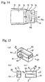
- a silencer device 80 in which a branch passage 82 having a fixed sectional shape is arranged in parallel with a main passage 81 and in which an entrance opening 83 and an exit opening 84 of the branch passage 82 are opened in front of and at the back of the main passage 81, as shown in Fig. 15.
- this silencer device is effective for the case in which the depth in the ventilating direction can be sufficient. Against the noises containing a low-frequency band, however, there arises a problem that the silencer device is hard to apply where the depth is restricted as in the front grille of the automobile.
- this silencer is characterized to silence both the sound waves of a fundamental frequency determined by the length of the silencing passage and the sound waves of a frequency which is the fundamental frequency multiplied by an integer.
- this silencer is troubled by a problem that its noise reducing effect is insufficient by any means against noises such as the engine noises covering a wide frequency band from a low frequency.
- the present invention has been conceived to solve the above-specified problems and has an object to provide a silencer unit and a silencer device which can be applied to a portion such as the front grille or bumper of an automobile unable to take a large area in a ventilation front and a depth in a ventilating direction.
- Another object of the present invention is to provide a ventilable silencer unit and a ventilable silencer device, which can not only reduce noises such as the external noises of an engine over a relatively wide frequency band but also retain the draft such as cooling air into the engine room sufficiently.
- a ventilable silencer unit and a ventilable silencer device for achieving the objects described above are constructed in the following manners.
- a ventilable silencer unit comprising a box body including, a ventilation portion, a silencer portion adjacent to said ventilation portion and a dividing partition located between said ventilation portion and said silencer portion,
- These plural silencing passages are set in length to resonate with the sound waves of the target noises having a plurality of frequencies to be silenced, and are constructed to attenuate those sound waves.
- the silencer is formed into the unit of box body so that it can be arranged in the ventilating passage requiring the draft. Moreover, the silencer is provided with the plurality of silencing passages of different lengths and different resonance frequencies. Therefore, the number of frequencies of the sound to be silenced in the individual silencing passages is increased so that the silencer can silence a remarkably wide frequency band as a whole thereby to improve the noise reducing efficiency drastically.
- the silencer unit of the box body is provided with the plurality of silencing passages in the silencer portion of the box body and further with the partition plate and the passage extending partitions which are jointed to the box body or the dividing partition. Therefore, since the strength and rigidity of the silencer unit is raised, the silencer unit can be prevented from being deformed or broken, as might otherwise be accompanied by the vibrations or the like of the automobile.
- the partition walls of the ventilating passage are generally parallel to the ventilating direction so that they can retain a sufficient ventilating function without obstructing the draft.
- said plurality of silencing passages are formed as resonance type silencing passage having two open ends.
- C designates the sound velocity
- n designates a natural number of 1, 2, 3, - - -, and so on.
- the resonance frequency fan to be erased depends on the passage length but hardly on the sectional shape so that the degree of freedom of the size of the silencing passages is enlarged to simplify the design and the manufacture.
- resonance type silencing passages having two open ends are partitioned with the passage extending partitions so that their length can be enlarged. Therefore, the silencer unit can be shortened in depth to reduce the thickness in the ventilating direction.
- the ventilable silencer unit according to the present invention is constructed such that said plurality of silencing passages include a branch type silencing passage having only one open end.
- the branch type silencing passage can have a shorter passage length and a lower fundamental frequency than in the resonance type silencing passage having two open ends so that it can have a high effect to reduce the noises in the low-frequency range.
- the ventilable silencer unit thus constructed can be disposed in the ventilation portion of the front grille or bumper of an automobile.
- ventilable silencer unit is enabled to make its depth relatively short by its characteristics so that it can be arranged and effectively used in the relatively shallow ventilation portion of the front grille or bumper of the automobile.
- the arrangement of the silencer unit in the front grille and the bumper can be made by changing the silencer unit sizes and the kinds.
- one of said silencing passages has the length for silencing the sound wave having fundamental frequency of the noise at the engine idle driving time of said automobile.
- the external noises of the automobile raise the problem when the automobile stops in an idle run so that they can be reduced more effectively by setting the passage length of the silencing passage according to their fundamental frequency in the idle run.
- a ventilable silencer device can be formed by jointing a plurality of ventilable silencer units.
- ventilable silencer units can be expanded to a wider area by jointing them with their open faces being in the same direction.
- the fundamental frequencies of the individual silencing passages of those ventilable silencer units can be suitably selected by selecting the passage lengths. It is, therefore, possible to provide a silencer device having a higher silencing performance.
- the silencer unit according to the present invention can be especially designed to have a short depth so that it can be assembled by jointing its upper and lower faces and its side wall plates each other as by assembling blocks.
- the assembly can be made by connecting the silencer units in the longitudinal direction by jointing the rear wall plate and the front wall plate. Therefore, the silencer device can be formed by combining the units into shapes matching the individual mounting place.
- the units can be handled altogether, so that they can be easily stored, transported and mounted.
- the ventilable silencer device according to the present invention can be disposed in the ventilation portion of the front grille or bumper of an automobile.
- the ventilable silencer device is disposed in the narrow introduction portion such as the ventilation portion of the front grille or bumper, i.e., the portion facing the engine room of the automobile. Then, this ventilable silencer device is high in the silencing efficiency over a wide frequency band from a relatively low frequency. Therefore, the frequency component in the relatively wide range of the wide-band external noises such as the engine noises to be radiated to the outside of the vehicle is silenced to reduce the external noises remarkably.
- the silencer device can be satisfactorily mounted on the vehicle.
- the ventilation is easily retained so that the cooling air of the engine is efficiently introduced into the engine room.
- Fig. 1 is a schematic perspective view showing a ventilable silencer unit according to a first embodiment of the present invention.
- Fig. 2 is an exploded perspective view showing the inside of the ventilable silencer unit of Fig. 1.
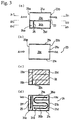
- FIG. 3 presenting diagrams showing the inside of the ventilable silencer unit of Fig. 1: (a) a sectional side elevation: (b) a section of Z1 - Z1 of (a); (c) a section of Z2 - Z2 of (a); and (d) a section of Z3 - Z3 of (a).
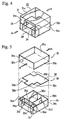
- Fig. 4 is a schematic perspective view showing a ventilable silencer unit according to a second embodiment of the present invention.
- Fig. 5 is an exploded perspective view showing the inside of the ventilable silencer unit of Fig. 4.
- FIG. 6 presenting diagrams showing the inside of the ventilable silencer unit of Fig. 4: (a) a sectional side elevation; (b) a section of Z1 - Z1 of (a); (c) a section of Z2 - Z2 of (a); and (d) a section of Z3 - Z3 of (a).
- Fig. 7 is a schematic perspective view showing a ventilable silencer unit according to a third embodiment of the present invention.
- Fig. 8 is an exploded perspective view showing the inside of the ventilable silencer unit of Fig. 7.
- FIG. 9 presenting diagrams showing the inside of the ventilable silencer unit of Fig. 7: (a) a sectional side elevation; (b) a section of Z1 - Z1 of (a); (c) a section of Z2 - Z2 of (a); (d) a section of Z3 - Z3 of (a); (e) a section of X1 - X1 of (a); and (f) a section of X2 - X2 of (a).
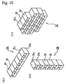
- FIG. 10 presenting diagrams showing ventilable silencer devices formed by combining ventilable silencer units; (a) a ventilable silencer device having a horizontally long shape; (b) a ventilable silencer device having a vertically long shape; and (c) a ventilable silencer device having a planar shape.
- Fig. 11 is a perspective view of an automobile and shows one example of a grille and a bumper, in which the ventilable silencer device of the present invention is arranged.
- Fig. 12 is a sectional side elevation of a grille portion and shows an example in which a ventilable silencer device of the present invention is arranged in the grille of the automobile.
- Fig. 13 is a schematic diagram for explaining the silencing principle of the silencer unit of the present invention.
- Fig. 14 is a schematic diagram showing a relation between the engine room and the front grille of an automobile.
- Fig. 15 is a perspective view showing a silencer device of the prior art.
- a standing wave is generated by resonances in a tube (or passage) opened at its two ends and having a length L, when acoustic vibrations are generated in the vicinity of the tube.
- the standing wave is a sound wave satisfying the condition that the sound pressure is zero at the two ends of the tube, Therefore, the fundamental vibrations have a frequency in which the length L corresponds to one half of the wavelength, and a sound wave having a frequency of integral times as long as the half wavelength so that they also exist as the standing wave.
- This phenomenon is the silencing principle in the silencing passage having the two open ends in the present invention.
- the silencer as called the "branch type" is constructed of a tube (or passage) having one end opened and the other closed.
- this tube there is generated the standing wave which satisfies the condition that the sound pressure is zero at the open end and the maximum (to have a zero particle velocity) at the closed end.
- a silencer unit 20 of the first embodiment of the present invention is formed to include a box body 21, and a dividing partition 22 parallel to the upper face 21u and the lower face 21d of the box body 21.
- This dividing partition 22 divides the box body 21 into a ventilation portion 23 and a silencer portion 24.
- the silencer unit 20 is formed of the box body 21 including the ventilation portion 23 for introducing the air from the front face of the front grille of an automobile into the engine room, for example, and the silencer portion 24 adjacent to the ventilation portion 23 through the dividing partition 22.
- This ventilation portion 23 is provided with openings 23a and 23b in front of and at the back of the box body 21, and a ventilable ventilating passage 23c enclosed by the side wall plates 21s and 21s and the upper face 21u of the box body 21.
- this ventilating passage 23c By the provision of this ventilating passage 23c, it is possible to retain a sufficient ventilation function. By adjusting the ratio between the sectional area of the ventilation portion 23 and the sectional area of the silencer portion 24. moreover, it is possible to easily adjust the balance between the ventilating function and the silencing function.
- the silencer portion 24 is formed by closing the box body 21 in the longitudinal direction with a front wall plate 21f and a rear wall plate 21b, and by forming a plurality of silencer passages 24a and 24b having different passage lengths La2 and Lb2 with a partition plate 25.
- the dividing partition 22 is provided with openings 22a to 22d to form the opening ends of the silencing passages 24a and 24b into the ventilating passage 23c thereby to form the resonance type silencing passages 24a and 24b having two open ends.
- the opening 22b and 22c are the substantially continuous notches of the dividing partition 22.
- the silencing passage 24b is provided with passage extending partitions 26a and 26b so that the passage length Lb2 may be enlarged to lower the fundamental frequency of the resonant sound waves of the silencing passage 24b (Fig. 2).
- the passage extending partition 26a and 26b reaching the dividing partition 22 from the lower face 21d the passage extending partition 26a is formed to have an opening on the front side, and the passage extending partition 26b is formed to have an opening on the rear side.
- the silencing passage 24b of the passage length Lb2 is formed between the opening 22c and the opening 22d.
- the silencer unit 20 is constructed to have the ventilating passage 23c and the resonance type silencing passages 24a and 24b having two open ends.
- a silencer unit 30 according to a second embodiment with reference to Fig. 4 to Fig. 6.
- the construction of a ventilation portion 33 is the same as that of the first embodiment so that its description will be omitted.
- the description will be made on a different portion, i.e., a silencer portion 34.
- the silencer portion 34 of the silencer unit 30 of the second embodiment of the present invention is formed by closing a box body 31 in the longitudinal direction with a front wall plate 31f and a rear wall plate 31b, and by forming a plurality of silencer passages 34a to 34d having different passage lengths La3, Lb3 and Lc3 with a plurality of partition plates 35a, 35b and 35c.
- these silencing passages 34a to 34d are made to communicate with a ventilating passage 33c by openings 32a to 32d formed in a dividing partition 32.
- branch type silencing passages 34a and 34b each having only one open end and the resonance type silencing passages 34c and 34d each having two open ends.
- the silencing passage 34d is provided with passage extending partitions 36a and 36b to enlarge a passage length Ld3 thereby to lower the fundamental frequency of the resonant sound waves of the silencing passage 34d.
- this silencer unit 30 is constructed to have the ventilating passage 33c, the branch type silencing passages 34a and 34b each having only one open end, and the resonance type silencing passages 34c and 34d each having two open ends.
- a silencer unit 40 according to a third embodiment with reference to Fig. 7 to Fig. 9.
- the construction of a ventilation portion 43 is the same as that of the first embodiment so that its description will be omitted.
- the description will be made on a different portion, i.e., a silencer portion 44.
- the silencer portion 44 of the silencer unit 40 of the third embodiment of the present invention is formed by closing a box body 41 in the longitudinal direction with a front wall plate 41f and a rear wall plate 41b, and by forming a plurality of silencer passages 44a and 44b having different passage lengths La4 and Lb4 with a partition plate 45.
- a dividing partition 42 is provided with openings 42a to 42d to form open ends of the silencing passages 44a and 44b into a ventilating passage 43c to form the resonance type silencing passages 44a and 44b having two open ends.
- the silencing passage 44b is provided with passage extending partitions 46a to 46e to enlarge a passage length Lb4 thereby to lower the fundamental frequency of the resonant sound waves of the silencing passage 44b.
- this silencer unit 40 is constructed to have the ventilating passage 43c and the resonance type silencing passages 44a and 44b each having two open ends.
- the silencer units 20, 30 and 40 are determined in their sizes by the noise characteristics of the individual objects to be silenced, but are so constructed that their ventilating passages may be identical in heights to the grill opening when the units are applied to the front grille.
- the resonance type silencing passages resonating with the frequency of 1 kHz and having two open ends have a passage length of 170 mm if the sound velocity is assumed to be 340 m/s.
- the ventilation portions 13, 23, 33 and 43 and the silencer portions 14, 24, 34 and 44 are determined in their size ratios by the balance between the drafts and the silencing performances.
- those portions are exemplified to have identical sizes, but the present invention should not be limited thereto.
- these silencer units can be made of various materials such as synthetic resins or light metals.
- sound absorbing materials such as urethane or glass wool can be mounted considering the sound absorbing efficiency, the ventilation effects and so on.
- this sound absorbing material has a sound absorbing effect for a higher frequency than that to be silenced by the sound absorbing material in the silencing passages so that a wider frequency band can be silenced.
- the ventilating direction is illustratively indicated by arrow A but may be reverse that of arrow A.
- the mounting has no directivity.
- the silencer unit is formed into the box shape so that it can be used by itself.
- several kinds of silencer units can be massively manufactured and arranged by selecting its number and the kind of the silencer unit suitably according to the noise characteristics of the object to be silenced or the mounting place thereby to effect remarkably efficient silencing operations.
- a silencer device having a ventilable wide area can be formed by coupling those silencer units.
- silencer devices 2A, 2B and 2C are formed into a horizontally long shape, a vertically long shape or a planar shape suited for the mounting place, as shown in Fig. 10, by jointing the side wall plates 21s of the silencer units 20 or by jointing the upper and lower faces 21u and 21d.
- Fig. 13 is exemplified by jointing not only the silencer units 20 of Fig. 4 but also the individual silencer units 30 and 40, and various kinds of silencer units may be combined to construct the silencer device.
- silencer units 20, 30 and 40 are combined to construct the silencer devices 2A, 2B and 2c, many silencer units can be handled altogether to facilitate their storing, transporting and mounting operations.
- the ventilation portion of the front grille or the bumper of the automobile have a relatively horizontally long shape, but the external noises can be effectively reduced by arranging the silencer device having a plurality of silencer units jointed.
- the silencer unit of the present invention can be arranged in the ventilation portion of a front grille 11 or a bumper 12 of an automobile 10 of Fig. 11.
- Fig. 12 shows an example of the case, in which the silencer unit is arranged in the front grille 11.
- the silencer unit 20 is arranged in two upper and lower stages with its ventilation portion 23 being adjusted to the opening of the front grille 11 formed below a bonnet 14.
- the silencer unit 20 is so mounted with its ventilation portion 23 being below the silencer portion 24 that neither water nor dust may be accumulated in the silencer portion 24.
- the silencer unit of the present invention has been specifically described mainly on the case in which it is applied to the ventilation portion of the front grille of the automobile, but it is needless to say that the silencer unit of the present invention should not be limited to the application to the automobile. It is apparent that the silencer unit can be disposed in the air intake or exhaust ports of devices or facilities needed to have the ventilating function thereby to reduce the noises, or that the silencer unit is disposed in the conduits of ventilation/air-conditioning apparatus thereby to reduce the fan noises.
- ventilable silencer unit of the present invention As has been described hereinbefore, the following effects can be achieved.
Landscapes
- Engineering & Computer Science (AREA)
- Chemical & Material Sciences (AREA)
- Combustion & Propulsion (AREA)
- Mechanical Engineering (AREA)
- General Engineering & Computer Science (AREA)
- Exhaust Silencers (AREA)
- Cooling, Air Intake And Gas Exhaust, And Fuel Tank Arrangements In Propulsion Units (AREA)
- Soundproofing, Sound Blocking, And Sound Damping (AREA)
Abstract
Description
C0 = kπ(2d)2/(tc + β x d/2).
Claims (7)
- A ventilable silencer unit comprising; a box body including, a ventilation portion, a silencer portion adjacent to said ventilation portion and a dividing partition located between said ventilation portion and said silencer portion,said ventilation portion is formed of a ventilating passage opened through front end and back end of said box body,said silencer portion being formed by closing front end and back end of said box body and including at least one partition plate to make a plurality of silencing passages of different length,each of said silencing passages communicating with said ventilation passage through at least one opening formed in said dividing partition, and,at least one of said silencing passages being provided with at least one passage extending partition to extend the length of said silencing passage.
- A ventilable silencer unit as set forth in Claim 1, characterized in that said plurality of silencing passages are formed as resonance type silencing passage having two open ends.
- A ventilable silencer unit as set forth in Claim 1, characterized in that said plurality of silencing passages include a branch type silencing passage having only one open end.
- A ventilable silencer unit as set forth in any of Claims 1 to 3, characterized in that said ventilable silencer unit is disposed in the ventilation portion of the front grille or bumper of an automobile.
- A ventilable silencer unit as set forth in Claim 4, characterized in that one of said silencing passages has the length for silencing the sound wave having fundamental frequency of the noise at the engine idle driving time of said automobile.
- A ventilable silencer device characterized in that said ventilable silencer device is formed by jointing a plurality of ventilable silencer units as set forth in any of Claims 1 to 3.
- A ventilable silencer device as set forth in Claim 6, characterized in that said ventilable silencer device is disposed in the ventilation portion of the front grille or bumper of an automobile.
Applications Claiming Priority (3)
| Application Number | Priority Date | Filing Date | Title |
|---|---|---|---|
| JP2000105898 | 2000-04-07 | ||
| JP2000105898A JP3885459B2 (en) | 2000-04-07 | 2000-04-07 | Ventilating muffler unit and ventilated muffler |
| PCT/JP2001/002720 WO2001079682A1 (en) | 2000-04-07 | 2001-03-30 | Ventilative noise suppressing unit for vehicle |
Publications (2)
| Publication Number | Publication Date |
|---|---|
| EP1191219A1 true EP1191219A1 (en) | 2002-03-27 |
| EP1191219A4 EP1191219A4 (en) | 2010-09-01 |
Family
ID=18619155
Family Applications (1)
| Application Number | Title | Priority Date | Filing Date |
|---|---|---|---|
| EP01917674A Withdrawn EP1191219A4 (en) | 2000-04-07 | 2001-03-30 | Ventilative noise suppressing unit for vehicle |
Country Status (5)
| Country | Link |
|---|---|
| US (1) | US6719078B2 (en) |
| EP (1) | EP1191219A4 (en) |
| JP (1) | JP3885459B2 (en) |
| CN (1) | CN1192157C (en) |
| WO (1) | WO2001079682A1 (en) |
Families Citing this family (35)
| Publication number | Priority date | Publication date | Assignee | Title |
|---|---|---|---|---|
| US20050161280A1 (en) * | 2002-12-26 | 2005-07-28 | Fujitsu Limited | Silencer and electronic equipment |
| JP4321106B2 (en) * | 2003-05-13 | 2009-08-26 | 三菱自動車工業株式会社 | Air conditioner for vehicles |
| US6981386B2 (en) * | 2003-07-11 | 2006-01-03 | General Electric Company | Silencing equipment for an air-cooling assembly |
| JP2005315087A (en) * | 2004-04-27 | 2005-11-10 | Tigers Polymer Corp | Air conditioning silencer system |
| JP4575121B2 (en) * | 2004-11-26 | 2010-11-04 | 株式会社大気社 | Interference silencer chamber |
| US7225780B2 (en) * | 2005-04-15 | 2007-06-05 | Visteon Global Technologies, Inc. | Modular resonator |
| US20090038875A1 (en) * | 2005-05-12 | 2009-02-12 | Arctic Cat, Inc. | Off-road engine configuration with noise reduction system |
| US20070045042A1 (en) * | 2005-08-25 | 2007-03-01 | L&L Products, Inc. | Sound reduction system with sound reduction chamber |
| US7819223B2 (en) * | 2006-04-03 | 2010-10-26 | Praxair Technology, Inc. | Silencer for adsorption-based gas separation systems |
| US7584743B2 (en) | 2006-10-03 | 2009-09-08 | Deere & Company | Noise reduction for an internal combustion engine |
| JP5227063B2 (en) * | 2008-04-10 | 2013-07-03 | 株式会社イノアックコーポレーション | Intake duct for vehicle |
| US20100246880A1 (en) * | 2009-03-30 | 2010-09-30 | Oxford J Craig | Method and apparatus for enhanced stimulation of the limbic auditory response |
| JP2012091745A (en) * | 2010-10-28 | 2012-05-17 | Hitachi Constr Mach Co Ltd | Transportation vehicle |
| CN102318459A (en) * | 2011-08-01 | 2012-01-11 | 华为技术有限公司 | Noise-reducing Device and Ventilation Noise-reducing System |
| DE102012011596B3 (en) * | 2012-06-13 | 2013-07-04 | Decoma (Germany) Gmbh | cradle |
| US9169750B2 (en) * | 2013-08-17 | 2015-10-27 | ESI Energy Solutions, LLC. | Fluid flow noise mitigation structure and method |
| US10274224B2 (en) * | 2015-11-04 | 2019-04-30 | Modine Manufacturing Company | Discharge plenum for packaged HVAC unit |
| KR101881096B1 (en) * | 2016-08-22 | 2018-08-17 | 서울대학교산학협력단 | Sound absorbing and insulating structures by tailoring sound velocities, and method of designing the sound absorbing and insulating structures |
| WO2018047153A1 (en) * | 2016-09-12 | 2018-03-15 | Acoustic Metamaterials Group Limited | Acoustic metamaterial sound absorber |
| US10928096B2 (en) | 2017-06-30 | 2021-02-23 | Robert Bosch Llc | Environmental control unit including noise reduction features |
| WO2019074061A1 (en) * | 2017-10-11 | 2019-04-18 | 富士フイルム株式会社 | Box-shaped soundproof structure and transportation unit |
| WO2019074802A1 (en) * | 2017-10-13 | 2019-04-18 | Out of the Box Audio, LLC | Thin film resonators |
| JP2019143478A (en) * | 2018-02-15 | 2019-08-29 | 株式会社Roki | Noise suppressor |
| US11193693B2 (en) * | 2018-09-05 | 2021-12-07 | Denso International America, Inc. | Sound suppression chamber for an HVAC air handling assembly |
| CN109243419B (en) * | 2018-10-26 | 2023-12-01 | 中国船舶重工集团公司第七一四研究所 | Ventilating sound insulation structure based on acoustic metamaterial technology |
| CN110763085A (en) * | 2019-09-17 | 2020-02-07 | 南京航空航天大学 | Micro-perforated orthogonally-arranged rectangular tube sandwich sound absorption and energy absorption composite structure |
| WO2021100478A1 (en) * | 2019-11-20 | 2021-05-27 | 本田技研工業株式会社 | Air intake structure for vehicle |
| JP7253148B2 (en) * | 2020-01-24 | 2023-04-06 | いすゞ自動車株式会社 | Vehicle intake noise reduction structure |
| CN115088032B (en) * | 2020-02-26 | 2025-09-23 | 富士胶片株式会社 | Silencers and air supply systems |
| US11776521B2 (en) | 2020-12-11 | 2023-10-03 | Toyota Motor Engineering & Manufacturing North America, Inc. | Sound absorbing structure having one or more acoustic scatterers attached to or forming a vehicle structure |
| DE102021209198A1 (en) * | 2021-08-20 | 2023-02-23 | Mahle International Gmbh | Low-noise flow diffuser and air conditioning with the same |
| PL439098A1 (en) * | 2021-09-30 | 2023-04-03 | Abb Schweiz Ag | Ventilation grille for electric vehicle charging stations |
| CN114475464B (en) * | 2022-03-08 | 2024-05-03 | 广州市樱杰汽车零部件有限公司 | Sound-absorbing cotton structure of automobile cover |
| KR102840958B1 (en) * | 2023-01-10 | 2025-08-01 | 대구대학교 산학협력단 | The noise suppresser |
| US12589411B2 (en) * | 2023-08-22 | 2026-03-31 | Toyota Motor Engineering & Manufacturing North America, Inc. | Systems for absorbing flexural waves acting upon a structure using monopole and dipole resonance |
Family Cites Families (15)
| Publication number | Priority date | Publication date | Assignee | Title |
|---|---|---|---|---|
| US3762489A (en) * | 1971-04-19 | 1973-10-02 | Caterpillar Tractor Co | Acoustical engine enclosure for earthmoving vehicles |
| BE792300A (en) * | 1971-12-06 | 1973-03-30 | Safety Vehicles Dev A B | EXHAUST NOISE MITIGATION EQUIPMENT |
| US4260037A (en) * | 1979-10-29 | 1981-04-07 | Deere & Company | Assembly for silencing engine cooling fan noise |
| JPH02149813A (en) | 1988-11-30 | 1990-06-08 | Asahi Optical Co Ltd | Foot switch adapter for photographing device of endoscope |
| JPH02149813U (en) * | 1989-05-22 | 1990-12-21 | ||
| US5014816A (en) * | 1989-11-09 | 1991-05-14 | E. I. Du Pont De Nemours And Company | Silencer for gas induction and exhaust systems |
| US5502283A (en) | 1991-09-25 | 1996-03-26 | Toyoda Boshoku Kabushiki Kaisha | Muffler |
| JPH0676649A (en) | 1992-08-25 | 1994-03-18 | Showa Electric Wire & Cable Co Ltd | Composite superconductor |
| JP2591221Y2 (en) * | 1993-03-31 | 1999-03-03 | 株式会社テネックス | Bypass silencer |
| JP3653763B2 (en) | 1994-12-20 | 2005-06-02 | 株式会社デンソー | Silencer |
| US5625172A (en) * | 1995-04-18 | 1997-04-29 | Caterpillar Inc. | Engine enclosure air inlet/discharge sound attenuator |
| GB9522724D0 (en) * | 1995-11-06 | 1996-01-10 | Acts Ltd | A noise attenuator for an induction system or an exhaust system |
| JP2000085498A (en) | 1998-09-10 | 2000-03-28 | Isuzu Motors Ltd | Automotive bumper |
| JP2000230413A (en) * | 1999-02-09 | 2000-08-22 | Honda Motor Co Ltd | Silencer for internal combustion engine |
| US6499956B2 (en) * | 2000-02-25 | 2002-12-31 | Inoac Corporation | Resonator-integrated fan shroud and resonator-integrated fan shroud with air intake duct |
-
2000
- 2000-04-07 JP JP2000105898A patent/JP3885459B2/en not_active Expired - Fee Related
-
2001
- 2001-03-30 US US09/980,634 patent/US6719078B2/en not_active Expired - Fee Related
- 2001-03-30 WO PCT/JP2001/002720 patent/WO2001079682A1/en not_active Ceased
- 2001-03-30 EP EP01917674A patent/EP1191219A4/en not_active Withdrawn
- 2001-04-06 CN CN01109757.4A patent/CN1192157C/en not_active Expired - Fee Related
Also Published As
| Publication number | Publication date |
|---|---|
| US20020153181A1 (en) | 2002-10-24 |
| CN1192157C (en) | 2005-03-09 |
| US6719078B2 (en) | 2004-04-13 |
| WO2001079682A1 (en) | 2001-10-25 |
| JP3885459B2 (en) | 2007-02-21 |
| CN1317629A (en) | 2001-10-17 |
| JP2001289024A (en) | 2001-10-19 |
| EP1191219A4 (en) | 2010-09-01 |
Similar Documents
| Publication | Publication Date | Title |
|---|---|---|
| US6719078B2 (en) | Ventilable silencer unit for vehicles | |
| EP0859906B1 (en) | A noise attenuator for an induction system or an exhaust system | |
| US5625172A (en) | Engine enclosure air inlet/discharge sound attenuator | |
| US7694660B2 (en) | Air induction housing having a perforated wall and interfacing sound attenuation chamber | |
| JP3653763B2 (en) | Silencer | |
| US12257958B2 (en) | Silencing member for electrified vehicle | |
| CN101165328B (en) | Sound suppression device for internal combustion engine system | |
| CN212724716U (en) | Silencing device and silence pipeline that has it | |
| JPH08170516A (en) | Muffler | |
| US7712577B2 (en) | Air induction housing having a perforated sound attenuation wall | |
| US20070295554A1 (en) | Sound Proofing Device and Device for Conducting a Fluid | |
| US20020040827A1 (en) | Reduced-noise device | |
| WO2022227698A1 (en) | Refrigeration apparatus and manufacturing method therefor | |
| JP3738579B2 (en) | Ventilating silencer | |
| JP3448388B2 (en) | Air conditioner silencer | |
| JP3325498B2 (en) | Ventilated sound insulation wall structure | |
| RU2328382C1 (en) | Light vehicle passenger saloon heating and ventilation system (options) | |
| CN221392930U (en) | Automobile air conditioner box and automobile | |
| JPH10282965A (en) | Sound absorbing device | |
| EP4664447A1 (en) | Soundproofing panel | |
| RU2829838C1 (en) | Noise-absorbing shield of energy compartment of vehicle | |
| JP2000272439A (en) | Sound insulation front grill panel, sound absorbing bumper and exterior noise reduction device | |
| JP2000087725A (en) | Sound attenuator | |
| JP3508337B2 (en) | Radiated sound reduction device | |
| JP2000085498A (en) | Automotive bumper |
Legal Events
| Date | Code | Title | Description |
|---|---|---|---|
| PUAI | Public reference made under article 153(3) epc to a published international application that has entered the european phase |
Free format text: ORIGINAL CODE: 0009012 |
|
| 17P | Request for examination filed |
Effective date: 20011204 |
|
| AK | Designated contracting states |
Kind code of ref document: A1 Designated state(s): AT BE CH CY DE DK ES FI FR GB GR IE IT LI LU MC NL PT SE TR |
|
| A4 | Supplementary search report drawn up and despatched |
Effective date: 20100803 |
|
| RIC1 | Information provided on ipc code assigned before grant |
Ipc: F02B 77/13 20060101ALN20100728BHEP Ipc: B60R 13/08 20060101ALI20100728BHEP Ipc: F02M 35/12 20060101AFI20011101BHEP |
|
| 17Q | First examination report despatched |
Effective date: 20101124 |
|
| STAA | Information on the status of an ep patent application or granted ep patent |
Free format text: STATUS: THE APPLICATION IS DEEMED TO BE WITHDRAWN |
|
| 18D | Application deemed to be withdrawn |
Effective date: 20120522 |