EP1191198A2 - Internal combustion center injection type engine and method for injecting fuel in an internal combustion center injection type engine - Google Patents
Internal combustion center injection type engine and method for injecting fuel in an internal combustion center injection type engine Download PDFInfo
- Publication number
- EP1191198A2 EP1191198A2 EP01122460A EP01122460A EP1191198A2 EP 1191198 A2 EP1191198 A2 EP 1191198A2 EP 01122460 A EP01122460 A EP 01122460A EP 01122460 A EP01122460 A EP 01122460A EP 1191198 A2 EP1191198 A2 EP 1191198A2
- Authority
- EP
- European Patent Office
- Prior art keywords
- piston
- fuel
- internal combustion
- type engine
- injection type
- Prior art date
- Legal status (The legal status is an assumption and is not a legal conclusion. Google has not performed a legal analysis and makes no representation as to the accuracy of the status listed.)
- Withdrawn
Links
Images


Classifications
-
- F—MECHANICAL ENGINEERING; LIGHTING; HEATING; WEAPONS; BLASTING
- F02—COMBUSTION ENGINES; HOT-GAS OR COMBUSTION-PRODUCT ENGINE PLANTS
- F02B—INTERNAL-COMBUSTION PISTON ENGINES; COMBUSTION ENGINES IN GENERAL
- F02B23/00—Other engines characterised by special shape or construction of combustion chambers to improve operation
- F02B23/08—Other engines characterised by special shape or construction of combustion chambers to improve operation with positive ignition
- F02B23/10—Other engines characterised by special shape or construction of combustion chambers to improve operation with positive ignition with separate admission of air and fuel into cylinder
- F02B23/101—Other engines characterised by special shape or construction of combustion chambers to improve operation with positive ignition with separate admission of air and fuel into cylinder the injector being placed on or close to the cylinder centre axis, e.g. with mixture formation using spray guided concepts
-
- F—MECHANICAL ENGINEERING; LIGHTING; HEATING; WEAPONS; BLASTING
- F02—COMBUSTION ENGINES; HOT-GAS OR COMBUSTION-PRODUCT ENGINE PLANTS
- F02B—INTERNAL-COMBUSTION PISTON ENGINES; COMBUSTION ENGINES IN GENERAL
- F02B75/00—Other engines
- F02B75/12—Other methods of operation
- F02B2075/125—Direct injection in the combustion chamber for spark ignition engines, i.e. not in pre-combustion chamber
-
- F—MECHANICAL ENGINEERING; LIGHTING; HEATING; WEAPONS; BLASTING
- F02—COMBUSTION ENGINES; HOT-GAS OR COMBUSTION-PRODUCT ENGINE PLANTS
- F02F—CYLINDERS, PISTONS OR CASINGS, FOR COMBUSTION ENGINES; ARRANGEMENTS OF SEALINGS IN COMBUSTION ENGINES
- F02F3/00—Pistons
- F02F3/26—Pistons having combustion chamber in piston head
-
- Y—GENERAL TAGGING OF NEW TECHNOLOGICAL DEVELOPMENTS; GENERAL TAGGING OF CROSS-SECTIONAL TECHNOLOGIES SPANNING OVER SEVERAL SECTIONS OF THE IPC; TECHNICAL SUBJECTS COVERED BY FORMER USPC CROSS-REFERENCE ART COLLECTIONS [XRACs] AND DIGESTS
- Y02—TECHNOLOGIES OR APPLICATIONS FOR MITIGATION OR ADAPTATION AGAINST CLIMATE CHANGE
- Y02T—CLIMATE CHANGE MITIGATION TECHNOLOGIES RELATED TO TRANSPORTATION
- Y02T10/00—Road transport of goods or passengers
- Y02T10/10—Internal combustion engine [ICE] based vehicles
- Y02T10/12—Improving ICE efficiencies
Definitions
- This invention relates to an internal combustion center injection type engine and to a method for injecting fuel in an internal combustion center injection type engine, especially to such an engine having an improvement in the shape of the upper surface of a piston defining a combustion chamber.
- a related art internal combustion injection engine of this kind is formed so as to improve the fuel consumption and exhaust gas characteristics by lean combustion made possible by injecting fuel from an injector directly into a combustion chamber.
- the methods of solving this problem include a method of delaying the injection time to a moment at which the fuel spray does not impinge upon a piston. In this case, the time for gasifying a fuel and mixing the fuel with the air becomes short, so that it is necessary to reduce the time needed to carry out the gasification and mixing operations.
- the methods conceivable as methods of satisfying the requirements include
- the method (1) requires passage narrowing, a variable mechanism and a supercharger become necessary so as to secure the quantity of the air when a rotational frequency and a load are high, so that this method is difficult to practice.
- the methods (2), (3) require that the atomization of fuel spray and the increasing of injection rate (injection quantity per unit time) are at odds with each other, i.e., these methods have contradictory demands for an injector. Therefore, these methods are difficult to practice.
- an internal combustion center injection type engine especially a multiple valve engine, with at least one combustion chamber defined by a cylinder bore, a cylinder head and a piston which is slidingly movable in said cylinder bore, an injector is provided on said cylinder head for injecting fuel towards a central portion of an upper surface of said piston, wherein a restricted surface for impinging a fuel spray is formed in the central portion of the upper surface of the piston.
- said restricted surface in the central portion of the upper surface of the piston is formed in such a manner that the fuel is injected from an injection port of the injector to the restricted surface when the piston is in the vicinity of the upper dead point of a suction stroke.
- said restricted surface in the central portion of the upper surface of the piston is provided close to the injection port of the injector when the piston is in the vicinity of the upper dead point of a suction stroke, especially such that a fuel spray which impinges said restricted surface spreads laterally with regard to a fuel injection direction.
- said cylinder head is provided with suction valves and exhaust valves opened to the combustion chamber, and the cylinder head, which is an upper surface of the combustion chamber, is provided with an ignition plug and said injector, wherein said ignition plug and said injector are provided substantially at a center of the upper surface of the combustion chamber formed by the cylinder head.
- the central portion of the upper surface of the piston is provided with an upwardly extending projection, and said restricted surface is formed on this projection.
- said restricted surface is a recess, especially concave shaped, and a circumferential edge is formed around said recess.
- said engine is a multiple valve engine, with at least two, especially three, suction valves and two exhaust valves per combustion chamber.
- said objective is solved by a method for injecting fuel in an internal combustion center injection type engine, especially an internal combustion center injection type engine according to at least one of the claims 1 to 7, with at least one combustion chamber defined by a cylinder bore, a cylinder head and a piston which is slidingly movable in said cylinder bore between an upper dead point and an lower dead point of the piston, wherein fuel is injected towards a central portion of an upper surface of said piston, and a fuel spray which is injected in the vicinity of the upper dead point of a suction stroke, impinges a restricted surface, which is formed in the central portion of the upper surface of the piston, and said fuel spray spreads substantially laterally with regard to a fuel injection direction.
- a deposition of fuel on the upper surface of the piston is restricted on the restricted surface which is formed in the central portion of the upper surface of the piston.
- the method for injecting fuel in an internal combustion center injection type engine comprises a fuel spray which is injected into the combustion chamber with the piston being outside of the vicinity of the upper dead point of a suction stroke does not impinge said restricted surface which is formed in the central portion of the upper surface of the piston.
- under high speed operation condition of the engine fuel injection starts with the piston being in the vicinity of the upper dead point of a suction stroke
- under low speed operation condition of the engine fuel injection starts with the piston being outside of the vicinity of the upper dead point of a suction stroke
- Fig. 1 to Fig. 7 show a mode 1 of an embodiment.
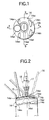
- a reference numeral 11 denotes a 4-cycle, 5-valve internal combustion injection engine, and a cylinder head 13 is fastened to a cylinder block 12 by head bolts (not shown).
- a piston 14 is vertically slidably inserted in a cylinder bore 12a of the cylinder block 12, and connected to a crankshaft via a connecting rod (not shown).
- a combustion chamber S is formed by the upper surface 14a of this piston 14, cylinder bore 12a and cylinder head 13.
- the outside air is introduced into this combustion chamber S via three suction valves 15 provided in the cylinder head 13, and a combustion gas is discharged from this combustion chamber S via two exhaust valves 16.
- These valves 15, 16 are formed so that the valves are operated by a cam rotated synchronously with a crankshaft and opened and closed with predetermined timing.
- the cylinder head 13 is provided therein with an ignition plug 17 so that an electrode portion 17a thereof projects from a substantially central position of the upper surface of the combustion chamber S, and an injector 18 is provided adjacently to this ignition plug 17, an injection port 18a of the injector 18 being opened in a substantially central position on the upper surface of the combustion chamber S.
- the upper surface 14a of the piston upon which fuel injected from the injection port 18a impinges is provided at its central portion with a projection 14a 2 extending upward from a flat circumferential general surface 14a 1 .
- This projection 14a 2 is provided with a slightly sunken substantially concave recess 14a 3 .
- run-off recesses 14a 4 for the suction valve 15 and run-off recesses 14a 5 for the exhaust valve 16 are formed as shown in Fig. 1.
- the time at which the fuel is injected from the injection port 18a of the injector 18 into this recess 14a 3 is set to a moment at which the piston reaches the vicinity of the upper dead point (including a position before the upper dead point) of a suction stroke.
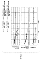
- Fig. 5 shows fuel injection period timing. As an engine speed increases, the injection starting time becomes earlier. Especially, in a high-speed engine, such as an engine for a motorcycle, the injection of a fuel is conducted when the piston is in the vicinity of an upper dead point of a suction stroke.
- Fig. 3A shows the condition of the fuel spray observed when the injection starting timing is 360° BTDC (the upper dead point of a suction stroke)
- Fig. 3B the condition of the fuel spray observed when the injection starting time is 340° BTDC (a position after an upper dead point of a suction stroke)
- Fig. 4A the condition of the fuel spray observed when the injection starting time is 320° BTDC.
- the uniform deposition of the fuel spray on the whole of the upper surface 14a of the piston can be prevented, and the atomization of the fuel spray is promoted at the same time.
- This enables a large engine torque to be obtained even when a fuel is lean, the fuel consumption to be improved and the total hydrocarbon (TCH) content of exhaust gas to be reduced.
- the projection 14a 2 when the projection 14a 2 is formed as in this mode of embodiment, a distance between the injection port 18a of the injector 18 and the upper surface of the piston can be reduced. Therefore, the fuel spray is atomized easily, and the fuel injection time can be delayed correspondingly, so that the blow-by of the fuel can be held down. Namely, when the piston is in a position in the vicinity of the upper dead point of a suction stroke, a period of time during which both the suction valve 15 and exhaust valve 16 are opened exists, so that there is the possibility that the fuel spray blows through the exhaust valve. However, the blow-by of the fuel spray can be restrained by delaying the injection time. Moreover, owing to the formation of the projection 14a 2 , compression ratio can be set large.
- the injection time for the recess- and projection-carrying piston 1 is 350° BTDC, for the recess- and projection-carrying piston 2 370° BTDC, and for the flat pistons 350° BTDC and 370° BTDC. In practice, the injection is started 27° after these injection starting moments.
- the use of the recess- and projection-carrying pistons 1, 2 causes the engine torque to become higher, the fuel consumption to become lower, and a total hydrocarbon (TCH) content of exhaust gas to become lower than the use of the flat piston even when the fuel is lean.
- THC total hydrocarbon
- the projections of the recess- and projection-carrying pistons 1, 2 according to the embodiments are designed depending on an injector's spray corner, especially the area on which the fuel spray impinges, and the control effect of fuel sticking.
- a big projection is required when a spray corner is big, and it enlarges fuel sticking extent.
- the recess- and projection-carrying pistons 1, 2 are designed depending on the heat load in the part of projection and the control effect of fuel sticking.
- the control effect of fuel sticking is more effective when the projection comprises some overhanging part.
- such overhanging part tends to become a heat spot.
- such overhanging part is restricted in view of said requirements.
- Fig. 8 to Fig. 10 show a mode 2 of embodiment.
- a recess 14a 3 in a projection 14a 2 of a piston 14 is formed more deeply than the corresponding recess in the mode 1 of embodiment.
- the power of the springing up of the fuel spray becomes large, and the degree of atomization of fuel spray is further raised.
- Fig. 11 to Fig. 14 show a mode 3 of embodiment.
- a projection 14a 2 is not formed on an upper surface 14a of a piston 14 but a recess 14a 3 only is formed. Said recess 14a 3 is clearly shown on the Figs. 11, 12, and 14B.
- the Figs. 13A, 13B and 14A are relating to the same teaching. However, for simplifying said Figs. 13A, 13B and 14A, which are directed to different piston positions and the related behavior of the injected fuel, said recess 14a 3 is not explicitly illustrated in said figures.
- An internal combustion center injection type engine comprises a combustion chamber S, which is formed from the upper portion of a cylinder bore 12a in which a piston 14 is slidingly moved in a cylinder block 12 and a cylinder head 13.
- the cylinder head 13 is provided therein with suction valves 15 and exhaust valves 16 opened to the combustion chamber S.
- the cylinder head 13, which is the upper surface of the combustion chamber S, is provided with an ignition plug 17 and an injector 18 at its center.
- the engine is constructed by forming a recess 14a 3 in the central portion of the upper surface 14a of a piston 14, in such a manner that a fuel is injected from the injection port 18a of an injector 18 to the recess 14a 3 when the piston 14 is in the vicinity of the upper dead point of a suction stroke.
- the central portion of the upper surface 14a of the piston 14 is provided with an upwardly extending projection 14a 2 , the mentioned recess 14a 3 being formed in this projection (14a 2 ).
- the embodiments described above are teaching an internal combustion center injection type engine, especially a multiple valve engine, with at least one combustion chamber S defined by a cylinder bore 12a, a cylinder head 13 and a piston (14) which is slidingly movable in said cylinder bore 12a.
- An injector 18 is provided on said cylinder head 13 for injecting fuel towards a central portion of an upper surface 14a of said piston 14, wherein a restricted surface 14a 3 for impinging a fuel spray is formed in the central portion of the upper surface 14a of the piston 14.
- said restricted surface 14a 3 in the central portion of the upper surface 14a of the piston 14 is formed in such a manner that the fuel is injected from an injection port 18a of the injector 18 to the restricted surface 14a 3 when the piston 14 is in the vicinity of the upper dead point (BTDC) of a suction stroke.
- Said restricted surface 14a 3 in the central portion of the upper surface 14a of the piston 14 is provided close to the injection port 18a of the injector 18 when the piston 14 is in the vicinity of the upper dead point (BTDC) of a suction stroke, such that a fuel spray which impinges said restricted surface 14a 3 spreads laterally with regard to a fuel injection direction.
- said cylinder head 13 is provided with suction valves 15 and exhaust valves 16 opened to the combustion chamber S.
- the cylinder head 13, which is an upper surface of the combustion chamber S, is provided with an ignition plug 17 and said injector 18. Said ignition plug 17 and said injector 18 are provided substantially at a center of the upper surface of the combustion chamber S formed by the cylinder head 13.
- the central portion of the upper surface 14a of the piston 14 is provided with an upwardly extending projection 14a 2 , and said restricted surface 14a 3 is formed on this projection 14a 2 .
- said restricted surface is a recess 14a 3 , especially concave shaped, and a circumferential edge is formed around said recess 14a 3 .
- inventions described above are teaching an internal combustion center injection type engine, wherein said engine is a multiple valve engine, with at least two, especially three, suction valves 15 and two exhaust valves per combustion chamber S.
- the embodiments described above are teaching a method for injecting fuel in an internal combustion center injection type engine, with at least one combustion chamber S defined by a cylinder bore 12a, a cylinder head 13 and a piston 14 which is slidingly movable in said cylinder bore 12a between an upper dead point (BTDC) and an lower dead point of the piston 14.
- Fuel is injected towards a central portion of an upper surface 14a of said piston 14.
- a fuel spray which is injected in the vicinity of the upper dead point (BTDC) of a suction stroke, impinges a restricted surface 14a 3 , which is formed in the central portion of the upper surface 14a of the piston 14.
- Said fuel spray spreads substantially laterally with regard to a fuel injection direction.
- An deposition of fuel on the upper surface 14a of the piston 14 is restricted on the restricted surface 14a 3 which is formed in the central portion of the upper surface 14a of the piston 14.
- a fuel spray which is injected into the combustion chamber S with the piston 14 being outside of the vicinity of the upper dead point (BTDC) of a suction stroke does not impinge said restricted surface 14a 3 which is formed in the central portion of the upper surface 14a of the piston 14.
- the internal combustion center injection type engine is formed so that the engine has a recess in the center portion of an upper surface of a piston, into which recess a fuel is injected from an injection port of an injector when a piston is in the vicinity of the upper dead point of a suction stroke. Therefore, the fuel spray impinges upon the surface of the recess and is sprung up. This enables the deposition of the fuel spray on the upper surface of the piston to be held down, and the atomization of fuel spray to be promoted. As a result, an increase in the engine torque and a decrease in the fuel consumption and the discharge rate of HC can be attained.
- the internal combustion center injection type engine has a projection extending upward from the portion of the upper surface of a piston which is in the vicinity of a central portion thereof, and a recess is in this projection. Therefore, the injection port of an injector and the recess can be brought close to each other, and the fuel spray can be atomized easily. This enables the moment at which the fuel injection is started to be delayed to when the piston is in the vicinity of the upper dead point of a suction stroke, by which the blow-by of the fuel at the valve-overlapping time to be held down, and further the compression ratio in the combustion chamber is increased owing to the projection.
Landscapes
- Engineering & Computer Science (AREA)
- Chemical & Material Sciences (AREA)
- Combustion & Propulsion (AREA)
- Mechanical Engineering (AREA)
- General Engineering & Computer Science (AREA)
- Combustion Methods Of Internal-Combustion Engines (AREA)
- Instructional Devices (AREA)
- Information Retrieval, Db Structures And Fs Structures Therefor (AREA)
- Management, Administration, Business Operations System, And Electronic Commerce (AREA)
Abstract
Description
- This invention relates to an internal combustion center injection type engine and to a method for injecting fuel in an internal combustion center injection type engine, especially to such an engine having an improvement in the shape of the upper surface of a piston defining a combustion chamber.
- A related art internal combustion injection engine of this kind is formed so as to improve the fuel consumption and exhaust gas characteristics by lean combustion made possible by injecting fuel from an injector directly into a combustion chamber.
- In order to carry out uniform combustion in a high-speed engine mounted on a motorcycle, etc., it is necessary in order to secure the time needed to gasify the fuel and mix the fuel with the air that a fuel be injected in the initial stage of a suction stroke both when the engine is a side-injection type engine and when the engine is a center-injection type engine. In this case it is difficult to inject fuel with a timing which prevents the fuel spray from impinging upon the piston.
- As a result, the fuel spray impinges upon the upper surface of the piston, and is turned into a liquid film on the same upper surface. This causes the gasification time to be delayed greatly or makes the gasification of a fuel impossible. Consequently, the deterioration of combustion and in its turn an increase in the fuel consumption and an increase in hydrocarbon exhaust discharge occur.
- This tendency is noticeable since the absolute time between an end of a fuel injection operation and the ignition of the gaseous mixture becomes shorter as engine speed increases. This poses a big problem in a high-speed engine.
- The methods of solving this problem include a method of delaying the injection time to a moment at which the fuel spray does not impinge upon a piston. In this case, the time for gasifying a fuel and mixing the fuel with the air becomes short, so that it is necessary to reduce the time needed to carry out the gasification and mixing operations. The methods conceivable as methods of satisfying the requirements include
- (1) a method of reinforcing flow of the air in the cylinder,
- (2) a method of atomizing the fuel spray from an injector, and
- (3) a method of increasing rate of injection of fuel from the injector and thereby finish the injection operation in a short time.
-
- However, since the method (1) requires passage narrowing, a variable mechanism and a supercharger become necessary so as to secure the quantity of the air when a rotational frequency and a load are high, so that this method is difficult to practice. The methods (2), (3) require that the atomization of fuel spray and the increasing of injection rate (injection quantity per unit time) are at odds with each other, i.e., these methods have contradictory demands for an injector. Therefore, these methods are difficult to practice.
- It is an objective of the present invention to provide an internal combustion center injection type engine and a method for injecting fuel in an internal combustion center injection type engine, wherein the fuel combustion is improved.
- According to the apparatus aspect of the present invention, said objective is solved by an internal combustion center injection type engine, especially a multiple valve engine, with at least one combustion chamber defined by a cylinder bore, a cylinder head and a piston which is slidingly movable in said cylinder bore, an injector is provided on said cylinder head for injecting fuel towards a central portion of an upper surface of said piston, wherein a restricted surface for impinging a fuel spray is formed in the central portion of the upper surface of the piston.
- According to a preferred embodiment, said restricted surface in the central portion of the upper surface of the piston is formed in such a manner that the fuel is injected from an injection port of the injector to the restricted surface when the piston is in the vicinity of the upper dead point of a suction stroke.
- According to a preferred embodiment, said restricted surface in the central portion of the upper surface of the piston is provided close to the injection port of the injector when the piston is in the vicinity of the upper dead point of a suction stroke, especially such that a fuel spray which impinges said restricted surface spreads laterally with regard to a fuel injection direction.
- In the internal combustion center injection type engine according to a preferred embodiment, said cylinder head is provided with suction valves and exhaust valves opened to the combustion chamber, and the cylinder head, which is an upper surface of the combustion chamber, is provided with an ignition plug and said injector, wherein said ignition plug and said injector are provided substantially at a center of the upper surface of the combustion chamber formed by the cylinder head.
- According to a preferred embodiment, the central portion of the upper surface of the piston is provided with an upwardly extending projection, and said restricted surface is formed on this projection.
- Preferably, said restricted surface is a recess, especially concave shaped, and a circumferential edge is formed around said recess.
- According to a preferred embodiment, said engine is a multiple valve engine, with at least two, especially three, suction valves and two exhaust valves per combustion chamber.
- According to the method aspect of the present invention, said objective is solved by a method for injecting fuel in an internal combustion center injection type engine, especially an internal combustion center injection type engine according to at least one of the
claims 1 to 7, with at least one combustion chamber defined by a cylinder bore, a cylinder head and a piston which is slidingly movable in said cylinder bore between an upper dead point and an lower dead point of the piston, wherein fuel is injected towards a central portion of an upper surface of said piston, and a fuel spray which is injected in the vicinity of the upper dead point of a suction stroke, impinges a restricted surface, which is formed in the central portion of the upper surface of the piston, and said fuel spray spreads substantially laterally with regard to a fuel injection direction. - Preferably, a deposition of fuel on the upper surface of the piston is restricted on the restricted surface which is formed in the central portion of the upper surface of the piston.
- The method for injecting fuel in an internal combustion center injection type engine according to a preferred embodiment comprises a fuel spray which is injected into the combustion chamber with the piston being outside of the vicinity of the upper dead point of a suction stroke does not impinge said restricted surface which is formed in the central portion of the upper surface of the piston.
- According to a preferred embodiment, under high speed operation condition of the engine fuel injection starts with the piston being in the vicinity of the upper dead point of a suction stroke, and under low speed operation condition of the engine fuel injection starts with the piston being outside of the vicinity of the upper dead point of a suction stroke.
- It is an advantage of the present invention to provide an internal combustion center injection type engine and to a method for injecting fuel in an internal combustion center injection type engine adapted to minimize the deposition of fuel spray on an upper surface of a piston, and promote the atomization of fuel.
- Preferred embodiments of the present invention are laid down in the dependent claims.
- In the following, the present invention is explained in greater detail with respect to several embodiments thereof in conjunction with the accompanying drawings, wherein:
- Fig. 1
- is a plan view of a piston in the
mode 1 of embodiment; - Fig. 2
- is a sectional view, which corresponds to a drawing taken along the line A-A in
Fig. 1, of the
same mode 1 of embodiment; - Fig. 3
- is sectional view, which corresponds to a drawing taken along the line B-B in
Fig. 1, of the
same mode 1 of embodiment, wherein Fig. 3A shows the embodiment in which a crank angle is 360° BTDC, and Fig. 3B the embodiment in which a crank angle is 340° BTDC; - Fig. 4
- is a sectional view, which corresponds to a drawing taken along the line B-B in
Fig. 1, of the
same mode 1 of embodiment, wherein Fig. 4A shows the embodiment in which a crank angle is 320° BTDC, and Fig. 4B the embodiment in which a crank angle is 300° BTDC; - Fig. 5
- is a graph showing injection time with respect to every engine speed in the
same mode 1 of embodiment; - Fig. 6
- is a perspective view showing an upper surface of a piston in the same model
of embodiment, wherein Fig. 6A shows a recess- and projection-carrying
piston 1, and Fig. 6B a recess- and projection-carryingpiston 2; - Fig. 7
- is a graph showing the relation between mixing ratio and engine torque, fuel
consumption and THC in the
same mode 1 of embodiment in comparison with similar relation in a related art engine of this kind; - Fig. 8
- is a sectional view, which corresponds to Fig. 2, showing a
mode 2 of embodiment; - Fig. 9
- is a sectional view, which corresponds to Fig. 3, of the
same mode 2 of embodiment, wherein Fig. 9A shows the condition in which a crank angle is 360° BTDC, and Fig. 9B the condition in which a crank angle is 340° BTDC; - Fig. 10
- is a sectional view, which corresponds to Fig. 4, of the
same mode 2 of embodiment, wherein Fig. 10A shows the condition in which a crank angle is 320° BTDC, and Fig. 10B the condition in which a crank angle is 300° BTDC; - Fig. 11
- is a plan view, which corresponds to Fig. 1, of a piston in the mode 3 of embodiment;
- Fig. 12
- is a sectional view, which corresponds to Fig. 2, of the same mode 3 of embodiment;
- Fig. 13
- is a sectional view, which corresponds to Fig. 3, of the
same mode 2 of embodiment, wherein Fig. 13A shows the condition in which a crank angle is 360° BTDC, and Fig. 13B the condition in which a crank angle is 340° BTDC; and - Fig. 14
- is a sectional view, which corresponds to Fig. 4, of the
same mode 2 of embodiment, wherein Fig. 14A shows the condition in which a crank angle is 320° BTDC, and Fig. 14B the condition in which a crank angle is 300° BTDC. - Fig. 1 to Fig. 7 show a
mode 1 of an embodiment. - The construction will now be described first. Referring to the drawings, a
reference numeral 11 denotes a 4-cycle, 5-valve internal combustion injection engine, and acylinder head 13 is fastened to acylinder block 12 by head bolts (not shown). - A
piston 14 is vertically slidably inserted in acylinder bore 12a of thecylinder block 12, and connected to a crankshaft via a connecting rod (not shown). - A combustion chamber S is formed by the
upper surface 14a of thispiston 14, cylinder bore 12a andcylinder head 13. The outside air is introduced into this combustion chamber S via threesuction valves 15 provided in thecylinder head 13, and a combustion gas is discharged from this combustion chamber S via twoexhaust valves 16. Thesevalves - The
cylinder head 13 is provided therein with anignition plug 17 so that anelectrode portion 17a thereof projects from a substantially central position of the upper surface of the combustion chamber S, and aninjector 18 is provided adjacently to thisignition plug 17, aninjection port 18a of theinjector 18 being opened in a substantially central position on the upper surface of the combustion chamber S. - The
upper surface 14a of the piston upon which fuel injected from theinjection port 18a impinges is provided at its central portion with aprojection 14a2 extending upward from a flat circumferentialgeneral surface 14a1. Thisprojection 14a2 is provided with a slightly sunken substantiallyconcave recess 14a3. Around theprojection 14a2, run-offrecesses 14a4 for thesuction valve 15 and run-offrecesses 14a5 for theexhaust valve 16 are formed as shown in Fig. 1. - The time at which the fuel is injected from the
injection port 18a of theinjector 18 into thisrecess 14a3 is set to a moment at which the piston reaches the vicinity of the upper dead point (including a position before the upper dead point) of a suction stroke. - In this connection, Fig. 5 shows fuel injection period timing. As an engine speed increases, the injection starting time becomes earlier. Especially, in a high-speed engine, such as an engine for a motorcycle, the injection of a fuel is conducted when the piston is in the vicinity of an upper dead point of a suction stroke.
- The operation will now be described.
- When fuel spray is injected from the
injection port 18a of theinjector 18 toward therecess 14a3 of theupper surface 14a of the piston when the piston is in the vicinity of the upper dead point of a suction stroke, the fuel spray impinges upon the bottom surface of therecess 14a3, spreads laterally and flows so as to spring up slightly from a circumferential edge of therecess 14a3. Fig. 3A shows the condition of the fuel spray observed when the injection starting timing is 360° BTDC (the upper dead point of a suction stroke), Fig. 3B the condition of the fuel spray observed when the injection starting time is 340° BTDC (a position after an upper dead point of a suction stroke), and Fig. 4A the condition of the fuel spray observed when the injection starting time is 320° BTDC. - For the above-mentioned reason, the uniform deposition of the fuel spray on the whole of the
upper surface 14a of the piston can be prevented, and the atomization of the fuel spray is promoted at the same time. This enables a large engine torque to be obtained even when a fuel is lean, the fuel consumption to be improved and the total hydrocarbon (TCH) content of exhaust gas to be reduced. - Especially, when the
projection 14a2 is formed as in this mode of embodiment, a distance between theinjection port 18a of theinjector 18 and the upper surface of the piston can be reduced. Therefore, the fuel spray is atomized easily, and the fuel injection time can be delayed correspondingly, so that the blow-by of the fuel can be held down. Namely, when the piston is in a position in the vicinity of the upper dead point of a suction stroke, a period of time during which both thesuction valve 15 andexhaust valve 16 are opened exists, so that there is the possibility that the fuel spray blows through the exhaust valve. However, the blow-by of the fuel spray can be restrained by delaying the injection time. Moreover, owing to the formation of theprojection 14a2, compression ratio can be set large. - When the injection is started when the piston is in a position of 300° BTDC which is away from the upper dead point of a suction stroke, the fuel spray does not impinge upon the
upper surface 14a of the piston as shown in Fig. 4B, and, accordingly, a problem of the deposition of fuel spray does not arise. - A description will now be given on the basis of the results of experiments.
- Experiments for determining variations of values of the engine torque, fuel consumption and THC were conducted by using two recess- and projection-carrying
pistons 1, 2 (refer to Fig. 6) according to the embodiments having different sizes ofprojections 14a2 and recesses 14a3 and a related art flat piston having a flat upper surface with an engine speed set to 9000 rpm and a mixing ratio (A/F) of the fuel varied. In Fig. 6, the run-offrecesses - The injection time for the recess- and projection-carrying
piston 1 is 350° BTDC, for the recess- and projection-carryingpiston 2 370° BTDC, and for the flat pistons 350° BTDC and 370° BTDC. In practice, the injection is started 27° after these injection starting moments. - According to the above, it is understood that the use of the recess- and projection-carrying
pistons - The projections of the recess- and projection-carrying
pistons - Moreover, the recess- and projection-carrying
pistons - Fig. 8 to Fig. 10 show a
mode 2 of embodiment. - In this
mode 2 of embodiment, arecess 14a3 in aprojection 14a2 of apiston 14 is formed more deeply than the corresponding recess in themode 1 of embodiment. - According to the
mode 2 of embodiment, the power of the springing up of the fuel spray becomes large, and the degree of atomization of fuel spray is further raised. - Since the construction and operation of the other portions of this mode of embodiment are identical with those of the
mode 1 of embodiment, the descriptions thereof will be omitted. - When the fuel injection is started at a moment at which a piston is in a position of 300° BTDC which is away from the upper dead point of a suction stroke, the fuel spray does not impinge upon an
upper surface 14a of the piston as shown in Fig. 10B, so that a problem of the deposition of the fuel spray does not occur. - Fig. 11 to Fig. 14 show a mode 3 of embodiment.
- In this mode 3 of embodiment, a
projection 14a2 is not formed on anupper surface 14a of apiston 14 but arecess 14a3 only is formed.Said recess 14a3 is clearly shown on the Figs. 11, 12, and 14B. The Figs. 13A, 13B and 14A are relating to the same teaching. However, for simplifying said Figs. 13A, 13B and 14A, which are directed to different piston positions and the related behavior of the injected fuel, saidrecess 14a3 is not explicitly illustrated in said figures. - Even when this structure is employed, the deposition of the fuel spray on the
upper surface 14a of the piston is also held down, and the atomization of the fuel spray is also promoted. This enables an increase in the engine torque and a decrease in the fuel consumption and discharge rate of HC to be attained. - When the fuel injection is started at a moment at which a piston is in a position of 300° BTDC which is away from the upper dead point of a suction stroke, the fuel spray does not impinge upon an
upper surface 14a of the piston as shown in Fig. 14B, so that a problem of the deposition of the fuel spray does not occur. - An internal combustion center injection type engine according to the embodiments comprises a combustion chamber S, which is formed from the upper portion of a
cylinder bore 12a in which apiston 14 is slidingly moved in acylinder block 12 and acylinder head 13. Thecylinder head 13 is provided therein withsuction valves 15 andexhaust valves 16 opened to the combustion chamber S. Thecylinder head 13, which is the upper surface of the combustion chamber S, is provided with anignition plug 17 and aninjector 18 at its center. The engine is constructed by forming arecess 14a3 in the central portion of theupper surface 14a of apiston 14, in such a manner that a fuel is injected from theinjection port 18a of aninjector 18 to therecess 14a3 when thepiston 14 is in the vicinity of the upper dead point of a suction stroke. - According to some of the embodiments, the central portion of the
upper surface 14a of thepiston 14 is provided with an upwardly extendingprojection 14a2, the mentionedrecess 14a3 being formed in this projection (14a2). - The embodiments described above are teaching an internal combustion center injection type engine, especially a multiple valve engine, with at least one combustion chamber S defined by a
cylinder bore 12a, acylinder head 13 and a piston (14) which is slidingly movable in saidcylinder bore 12a. Aninjector 18 is provided on saidcylinder head 13 for injecting fuel towards a central portion of anupper surface 14a of saidpiston 14, wherein arestricted surface 14a3 for impinging a fuel spray is formed in the central portion of theupper surface 14a of thepiston 14. - According to the embodiments, said restricted
surface 14a3 in the central portion of theupper surface 14a of thepiston 14 is formed in such a manner that the fuel is injected from aninjection port 18a of theinjector 18 to the restrictedsurface 14a3 when thepiston 14 is in the vicinity of the upper dead point (BTDC) of a suction stroke. Said restrictedsurface 14a3 in the central portion of theupper surface 14a of thepiston 14 is provided close to theinjection port 18a of theinjector 18 when thepiston 14 is in the vicinity of the upper dead point (BTDC) of a suction stroke, such that a fuel spray which impinges said restrictedsurface 14a3 spreads laterally with regard to a fuel injection direction. - According to the embodiments, said
cylinder head 13 is provided withsuction valves 15 andexhaust valves 16 opened to the combustion chamber S. Thecylinder head 13, which is an upper surface of the combustion chamber S, is provided with anignition plug 17 and saidinjector 18. Said ignition plug 17 and saidinjector 18 are provided substantially at a center of the upper surface of the combustion chamber S formed by thecylinder head 13. - According to some embodiments described above, the central portion of the
upper surface 14a of thepiston 14 is provided with an upwardly extendingprojection 14a2, and said restrictedsurface 14a3 is formed on thisprojection 14a2. - According to embodiments described above, said restricted surface is a
recess 14a3, especially concave shaped, and a circumferential edge is formed around saidrecess 14a3. - The embodiments described above are teaching an internal combustion center injection type engine, wherein said engine is a multiple valve engine, with at least two, especially three,
suction valves 15 and two exhaust valves per combustion chamber S. - The embodiments described above are teaching a method for injecting fuel in an internal combustion center injection type engine, with at least one combustion chamber S defined by a
cylinder bore 12a, acylinder head 13 and apiston 14 which is slidingly movable in said cylinder bore 12a between an upper dead point (BTDC) and an lower dead point of thepiston 14. Fuel is injected towards a central portion of anupper surface 14a of saidpiston 14. A fuel spray which is injected in the vicinity of the upper dead point (BTDC) of a suction stroke, impinges a restrictedsurface 14a3, which is formed in the central portion of theupper surface 14a of thepiston 14. Said fuel spray spreads substantially laterally with regard to a fuel injection direction. An deposition of fuel on theupper surface 14a of thepiston 14 is restricted on the restrictedsurface 14a3 which is formed in the central portion of theupper surface 14a of thepiston 14. - A fuel spray which is injected into the combustion chamber S with the
piston 14 being outside of the vicinity of the upper dead point (BTDC) of a suction stroke does not impinge said restrictedsurface 14a3 which is formed in the central portion of theupper surface 14a of thepiston 14. - According to the method for injecting fuel in an internal combustion center injection type engine, under high speed operation condition of the engine fuel injection starts with the
piston 14 being in the vicinity of the upper dead point (BTDC) of a suction stroke. Under low speed operation condition of the engine fuel injection starts with thepiston 14 being outside of the vicinity of the upper dead point (BTDC) of a suction stroke. - According to the embodiments described above, the internal combustion center injection type engine is formed so that the engine has a recess in the center portion of an upper surface of a piston, into which recess a fuel is injected from an injection port of an injector when a piston is in the vicinity of the upper dead point of a suction stroke. Therefore, the fuel spray impinges upon the surface of the recess and is sprung up. This enables the deposition of the fuel spray on the upper surface of the piston to be held down, and the atomization of fuel spray to be promoted. As a result, an increase in the engine torque and a decrease in the fuel consumption and the discharge rate of HC can be attained.
- Furthermore, according to the embodiments described above, the internal combustion center injection type engine has a projection extending upward from the portion of the upper surface of a piston which is in the vicinity of a central portion thereof, and a recess is in this projection. Therefore, the injection port of an injector and the recess can be brought close to each other, and the fuel spray can be atomized easily. This enables the moment at which the fuel injection is started to be delayed to when the piston is in the vicinity of the upper dead point of a suction stroke, by which the blow-by of the fuel at the valve-overlapping time to be held down, and further the compression ratio in the combustion chamber is increased owing to the projection.
Claims (11)
- Internal combustion center injection type engine, especially a multiple valve engine, with at least one combustion chamber (S) defined by a cylinder bore (12a), a cylinder head (13) and a piston (14) which is slidingly movable in said cylinder bore (12a), an injector (18) is provided on said cylinder head (13) for injecting fuel towards a central portion of an upper surface (14a) of said piston (14), wherein a restricted surface (14a3) for impinging a fuel spray is formed in the central portion of the upper surface (14a) of the piston (14).
- Internal combustion center injection type engine according to claim 1, characterized in that said restricted surface (14a3) in the central portion of the upper surface (14a) of the piston (14) is formed in such a manner that the fuel is injected from an injection port (18a) of the injector (18) to the restricted surface (14a3) when the piston (14) is in the vicinity of the upper dead point (BTDC) of a suction stroke.
- Internal combustion center injection type engine according to claim 1 or 2, characterized in that said restricted surface (14a3) in the central portion of the upper surface (14a) of the piston (14) is provided close to the injection port (18a) of the injector (18) when the piston (14) is in the vicinity of the upper dead point (BTDC) of a suction stroke, especially such that a fuel spray which impinges said restricted surface (14a3) spreads laterally with regard to a fuel injection direction.
- Internal combustion center injection type engine according to at least one of the claims 1 to 3, characterized in that said cylinder head (13) is provided with suction valves (15) and exhaust valves (16) opened to the combustion chamber (S), and the cylinder head (13), which is an upper surface of the combustion chamber (S), is provided with an ignition plug (17) and said injector (18), wherein said ignition plug (17) and said injector (18) are provided substantially at a center of the upper surface of the combustion chamber (S) formed by the cylinder head (13).
- Internal combustion center injection type engine according to at least one of the claims 1 to 4, characterized in that the central portion of the upper surface (14a) of the piston (14) is provided with an upwardly extending projection (14a2), and said restricted surface (14a3) is formed on this projection (14a2).
- Internal combustion center injection type engine according to at least one of the claims 1 to 5, characterized in that said restricted surface is a recess (14a3), especially concave shaped, and a circumferential edge is formed around said recess (14a3).
- Internal combustion center injection type engine according to at least one of the claims 1 to 6, characterized in that said engine is a multiple valve engine, with at least two, especially three, suction valves (15) and two exhaust valves per combustion chamber (S).
- Method for injecting fuel in an internal combustion center injection type engine, especially an internal combustion center injection type engine according to at least one of the claims 1 to 7, with at least one combustion chamber (S) defined by a cylinder bore (12a), a cylinder head (13) and a piston (14) which is slidingly movable in said cylinder bore (12a) between an upper dead point (BTDC) and an lower dead point of the piston (14), wherein fuel is injected towards a central portion of an upper surface (14a) of said piston (14), and a fuel spray which is injected in the vicinity of the upper dead point (BTDC) of a suction stroke, impinges a restricted surface (14a3), which is formed in the central portion of the upper surface (14a) of the piston (14), and said fuel spray spreads substantially laterally with regard to a fuel injection direction.
- Method for injecting fuel in an internal combustion center injection type engine according to claim 8, characterized in that an deposition of fuel on the upper surface (14a) of the piston (14) is restricted on the restricted surface (14a3) which is formed in the central portion of the upper surface (14a) of the piston (14).
- Method for injecting fuel in an internal combustion center injection type engine according to claim 8 or 9, characterized by a fuel spray which is injected into the combustion chamber (S) with the piston (14) being outside of the vicinity of the upper dead point (BTDC) of a suction stroke does not impinge said restricted surface (14a3) which is formed in the central portion of the upper surface (14a) of the piston (14).
- Method for injecting fuel in an internal combustion center injection type engine according to at least one of the claims 8 to 10, characterized in that under high speed operation condition of the engine fuel injection starts with the piston (14) being in the vicinity of the upper dead point (BTDC) of a suction stroke, and under low speed operation condition of the engine fuel injection starts with the piston (14) being outside of the vicinity of the upper dead point (BTDC) of a suction stroke.
Applications Claiming Priority (2)
| Application Number | Priority Date | Filing Date | Title |
|---|---|---|---|
| JP2000385382 | 2000-09-20 | ||
| JP2000385382A JP2002183593A (en) | 2000-09-20 | 2000-12-19 | Signboard information retrieval system |
Publications (2)
| Publication Number | Publication Date |
|---|---|
| EP1191198A2 true EP1191198A2 (en) | 2002-03-27 |
| EP1191198A3 EP1191198A3 (en) | 2003-03-12 |
Family
ID=18852652
Family Applications (1)
| Application Number | Title | Priority Date | Filing Date |
|---|---|---|---|
| EP01122460A Withdrawn EP1191198A3 (en) | 2000-09-20 | 2001-09-20 | Internal combustion center injection type engine and method for injecting fuel in an internal combustion center injection type engine |
Country Status (2)
| Country | Link |
|---|---|
| EP (1) | EP1191198A3 (en) |
| JP (1) | JP2002183593A (en) |
Cited By (1)
| Publication number | Priority date | Publication date | Assignee | Title |
|---|---|---|---|---|
| DE102011106803A1 (en) * | 2011-07-06 | 2013-01-10 | Audi Ag | Internal combustion engine e.g. diesel engine for motor vehicle, has injection valve that is provided for injecting fuel into cylinder in direction of combustion chamber recess of piston |
Families Citing this family (3)
| Publication number | Priority date | Publication date | Assignee | Title |
|---|---|---|---|---|
| JP4218946B2 (en) * | 2003-05-12 | 2009-02-04 | アルパイン株式会社 | Navigation device |
| JP2009252087A (en) * | 2008-04-09 | 2009-10-29 | Nec Corp | Information providing system and information providing method |
| JP5792913B1 (en) * | 2014-01-30 | 2015-10-14 | 楽天株式会社 | Attribute display system, attribute display method, and attribute display program |
Citations (3)
| Publication number | Priority date | Publication date | Assignee | Title |
|---|---|---|---|---|
| DE3327998A1 (en) * | 1983-08-03 | 1985-02-14 | Volkswagenwerk Ag, 3180 Wolfsburg | Diesel internal combustion engine with air-distributing direct fuel injection |
| US4770138A (en) * | 1986-06-19 | 1988-09-13 | Nippon Clen Engine Research Institute Co. Ltd. | Fuel injection type internal combustion engine |
| JPH11210468A (en) * | 1998-01-27 | 1999-08-03 | Isuzu Motors Ltd | Combustion chamber of direct injection diesel engine |
Family Cites Families (6)
| Publication number | Priority date | Publication date | Assignee | Title |
|---|---|---|---|---|
| US4286557A (en) * | 1979-09-21 | 1981-09-01 | General Motors Corporation | Target injection stratified charge spark ignition engine |
| US4446830A (en) * | 1983-01-10 | 1984-05-08 | Ford Motor Company | Method of operating an engine with a high heat of vaporization fuel |
| FR2650630A1 (en) * | 1989-08-02 | 1991-02-08 | Renault | MULTI-CYLINDER ENGINE WITH FUEL INJECTION, COMPRISING FOUR VALVES PER CYLINDER |
| DE69430596T2 (en) * | 1993-12-28 | 2002-11-14 | Hitachi Ltd | Method and device for controlling an internal combustion engine |
| JP3152640B2 (en) * | 1998-01-05 | 2001-04-03 | 川崎重工業株式会社 | Fuel supply method for gasoline engine |
| US20010003281A1 (en) * | 1998-06-26 | 2001-06-14 | Kenji Mori | Combustion chamber for direct injection engine |
-
2000
- 2000-12-19 JP JP2000385382A patent/JP2002183593A/en active Pending
-
2001
- 2001-09-20 EP EP01122460A patent/EP1191198A3/en not_active Withdrawn
Patent Citations (3)
| Publication number | Priority date | Publication date | Assignee | Title |
|---|---|---|---|---|
| DE3327998A1 (en) * | 1983-08-03 | 1985-02-14 | Volkswagenwerk Ag, 3180 Wolfsburg | Diesel internal combustion engine with air-distributing direct fuel injection |
| US4770138A (en) * | 1986-06-19 | 1988-09-13 | Nippon Clen Engine Research Institute Co. Ltd. | Fuel injection type internal combustion engine |
| JPH11210468A (en) * | 1998-01-27 | 1999-08-03 | Isuzu Motors Ltd | Combustion chamber of direct injection diesel engine |
Cited By (1)
| Publication number | Priority date | Publication date | Assignee | Title |
|---|---|---|---|---|
| DE102011106803A1 (en) * | 2011-07-06 | 2013-01-10 | Audi Ag | Internal combustion engine e.g. diesel engine for motor vehicle, has injection valve that is provided for injecting fuel into cylinder in direction of combustion chamber recess of piston |
Also Published As
| Publication number | Publication date |
|---|---|
| JP2002183593A (en) | 2002-06-28 |
| EP1191198A3 (en) | 2003-03-12 |
Similar Documents
| Publication | Publication Date | Title |
|---|---|---|
| KR940001929B1 (en) | Timing of fuel injected engines | |
| US5553579A (en) | Fuel injection system for two-cycle engine | |
| US7104255B2 (en) | Method and apparatus for controlling operation of internal combustion engine, and the internal combustion engine | |
| US6928997B2 (en) | Direct injection engine | |
| EP1179676A1 (en) | In-cylinder injection engine | |
| US20210040913A1 (en) | Method for operating a spark-ignition internal combustion engine | |
| US6612282B2 (en) | Combustion chamber for DISI engine | |
| US6318308B1 (en) | Increased compression ratio diesel engine assembly for retarded fuel injection timing | |
| US6032641A (en) | Fuel injection device for diesel engine | |
| US6637403B2 (en) | Fuel injection control method for a direct-injection internal-combustion engine | |
| US5970945A (en) | Barrier divided combustion chamber for fuel injection two-stroke engine | |
| EP1191198A2 (en) | Internal combustion center injection type engine and method for injecting fuel in an internal combustion center injection type engine | |
| US6070566A (en) | Piston for direct injection combustion chamber used in internal combustion engine | |
| US20020129787A1 (en) | Spark ignited internal combustion engine with at least one cylinder | |
| EP2282041B1 (en) | Fuel injection control apparatus with pre- and post-injection | |
| JP3523278B2 (en) | Combustion chamber of internal combustion engine | |
| JPH1068319A (en) | In-cylinder direct injection spark ignition engine | |
| JPH09217627A (en) | Direct injection lean burn high compression ratio gasoline engine | |
| KR0184165B1 (en) | Gasoline engine for a car having a squash piston | |
| JPH0510137A (en) | Cylinder injection type internal combustion engine | |
| JPH0533650A (en) | 2-cycle internal combustion engine | |
| JP4341488B2 (en) | Internal combustion engine | |
| JPH10325377A (en) | Spark ignition internal combustion engine | |
| JP2002089268A (en) | Center injection type direct injection engine | |
| JP2006002719A (en) | Control device for internal combustion engine |
Legal Events
| Date | Code | Title | Description |
|---|---|---|---|
| PUAI | Public reference made under article 153(3) epc to a published international application that has entered the european phase |
Free format text: ORIGINAL CODE: 0009012 |
|
| AK | Designated contracting states |
Kind code of ref document: A2 Designated state(s): AT BE CH CY DE DK ES FI FR GB GR IE IT LI LU MC NL PT SE TR |
|
| AX | Request for extension of the european patent |
Free format text: AL;LT;LV;MK;RO;SI |
|
| PUAL | Search report despatched |
Free format text: ORIGINAL CODE: 0009013 |
|
| AK | Designated contracting states |
Kind code of ref document: A3 Designated state(s): AT BE CH CY DE DK ES FI FR GB GR IE IT LI LU MC NL PT SE TR Designated state(s): AT BE CH CY DE DK ES FI FR GB GR IE IT LI LU MC NL PT SE TR |
|
| AX | Request for extension of the european patent |
Extension state: AL LT LV MK RO SI |
|
| 17P | Request for examination filed |
Effective date: 20030403 |
|
| AKX | Designation fees paid |
Designated state(s): AT BE CH CY DE DK ES FI FR GB GR IE IT LI LU MC NL PT SE TR |
|
| 17Q | First examination report despatched |
Effective date: 20060710 |
|
| STAA | Information on the status of an ep patent application or granted ep patent |
Free format text: STATUS: THE APPLICATION IS DEEMED TO BE WITHDRAWN |
|
| 18D | Application deemed to be withdrawn |
Effective date: 20061121 |