EP1191194A2 - Valve for a control muffler - Google Patents
Valve for a control muffler Download PDFInfo
- Publication number
- EP1191194A2 EP1191194A2 EP01122296A EP01122296A EP1191194A2 EP 1191194 A2 EP1191194 A2 EP 1191194A2 EP 01122296 A EP01122296 A EP 01122296A EP 01122296 A EP01122296 A EP 01122296A EP 1191194 A2 EP1191194 A2 EP 1191194A2
- Authority
- EP
- European Patent Office
- Prior art keywords
- shaft
- valve
- support shaft
- exhaust pipe
- shaft supporting
- Prior art date
- Legal status (The legal status is an assumption and is not a legal conclusion. Google has not performed a legal analysis and makes no representation as to the accuracy of the status listed.)
- Granted
Links
Images


Classifications
-
- F—MECHANICAL ENGINEERING; LIGHTING; HEATING; WEAPONS; BLASTING
- F01—MACHINES OR ENGINES IN GENERAL; ENGINE PLANTS IN GENERAL; STEAM ENGINES
- F01N—GAS-FLOW SILENCERS OR EXHAUST APPARATUS FOR MACHINES OR ENGINES IN GENERAL; GAS-FLOW SILENCERS OR EXHAUST APPARATUS FOR INTERNAL-COMBUSTION ENGINES
- F01N1/00—Silencing apparatus characterised by method of silencing
- F01N1/16—Silencing apparatus characterised by method of silencing by using movable parts
- F01N1/165—Silencing apparatus characterised by method of silencing by using movable parts for adjusting flow area
-
- F—MECHANICAL ENGINEERING; LIGHTING; HEATING; WEAPONS; BLASTING
- F16—ENGINEERING ELEMENTS AND UNITS; GENERAL MEASURES FOR PRODUCING AND MAINTAINING EFFECTIVE FUNCTIONING OF MACHINES OR INSTALLATIONS; THERMAL INSULATION IN GENERAL
- F16K—VALVES; TAPS; COCKS; ACTUATING-FLOATS; DEVICES FOR VENTING OR AERATING
- F16K15/00—Check valves
- F16K15/02—Check valves with guided rigid valve members
- F16K15/025—Check valves with guided rigid valve members the valve being loaded by a spring
- F16K15/026—Check valves with guided rigid valve members the valve being loaded by a spring the valve member being a movable body around which the medium flows when the valve is open
-
- F—MECHANICAL ENGINEERING; LIGHTING; HEATING; WEAPONS; BLASTING
- F16—ENGINEERING ELEMENTS AND UNITS; GENERAL MEASURES FOR PRODUCING AND MAINTAINING EFFECTIVE FUNCTIONING OF MACHINES OR INSTALLATIONS; THERMAL INSULATION IN GENERAL
- F16K—VALVES; TAPS; COCKS; ACTUATING-FLOATS; DEVICES FOR VENTING OR AERATING
- F16K15/00—Check valves
- F16K15/02—Check valves with guided rigid valve members
- F16K15/03—Check valves with guided rigid valve members with a hinged closure member or with a pivoted closure member
- F16K15/033—Check valves with guided rigid valve members with a hinged closure member or with a pivoted closure member spring-loaded
-
- F—MECHANICAL ENGINEERING; LIGHTING; HEATING; WEAPONS; BLASTING
- F01—MACHINES OR ENGINES IN GENERAL; ENGINE PLANTS IN GENERAL; STEAM ENGINES
- F01N—GAS-FLOW SILENCERS OR EXHAUST APPARATUS FOR MACHINES OR ENGINES IN GENERAL; GAS-FLOW SILENCERS OR EXHAUST APPARATUS FOR INTERNAL-COMBUSTION ENGINES
- F01N2450/00—Methods or apparatus for fitting, inserting or repairing different elements
- F01N2450/22—Methods or apparatus for fitting, inserting or repairing different elements by welding or brazing
-
- Y—GENERAL TAGGING OF NEW TECHNOLOGICAL DEVELOPMENTS; GENERAL TAGGING OF CROSS-SECTIONAL TECHNOLOGIES SPANNING OVER SEVERAL SECTIONS OF THE IPC; TECHNICAL SUBJECTS COVERED BY FORMER USPC CROSS-REFERENCE ART COLLECTIONS [XRACs] AND DIGESTS
- Y10—TECHNICAL SUBJECTS COVERED BY FORMER USPC
- Y10T—TECHNICAL SUBJECTS COVERED BY FORMER US CLASSIFICATION
- Y10T137/00—Fluid handling
- Y10T137/7722—Line condition change responsive valves
- Y10T137/7837—Direct response valves [i.e., check valve type]
- Y10T137/7898—Pivoted valves
- Y10T137/7901—Valve head movably connected for accommodation to seat
-
- Y—GENERAL TAGGING OF NEW TECHNOLOGICAL DEVELOPMENTS; GENERAL TAGGING OF CROSS-SECTIONAL TECHNOLOGIES SPANNING OVER SEVERAL SECTIONS OF THE IPC; TECHNICAL SUBJECTS COVERED BY FORMER USPC CROSS-REFERENCE ART COLLECTIONS [XRACs] AND DIGESTS
- Y10—TECHNICAL SUBJECTS COVERED BY FORMER USPC
- Y10T—TECHNICAL SUBJECTS COVERED BY FORMER US CLASSIFICATION
- Y10T137/00—Fluid handling
- Y10T137/7722—Line condition change responsive valves
- Y10T137/7837—Direct response valves [i.e., check valve type]
- Y10T137/7898—Pivoted valves
- Y10T137/7902—Valve mounted on end of pipe
-
- Y—GENERAL TAGGING OF NEW TECHNOLOGICAL DEVELOPMENTS; GENERAL TAGGING OF CROSS-SECTIONAL TECHNOLOGIES SPANNING OVER SEVERAL SECTIONS OF THE IPC; TECHNICAL SUBJECTS COVERED BY FORMER USPC CROSS-REFERENCE ART COLLECTIONS [XRACs] AND DIGESTS
- Y10—TECHNICAL SUBJECTS COVERED BY FORMER USPC
- Y10T—TECHNICAL SUBJECTS COVERED BY FORMER US CLASSIFICATION
- Y10T137/00—Fluid handling
- Y10T137/7722—Line condition change responsive valves
- Y10T137/7837—Direct response valves [i.e., check valve type]
- Y10T137/7904—Reciprocating valves
- Y10T137/7922—Spring biased
Definitions
- the present invention relates to a valve for a control muffler placed in an open end of an exhaust pipe in a muffler or the like, to be opened and closed so as to maintain exhaust pressure of a muffler chamber on the upstream side, to a predetermined value or smaller.
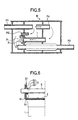
- an exhaust gas pressure sensitive control muffler is configured in the following manner. During a low engine speed period when the exhaust gas pressure is low, the pressure of the exhaust gas flowing from an inlet pipe P1 into the muffler M is low. Therefore, a countermeasure against noises is taken so that, as shown in Fig. 5, therefore, a closed state of a valve element 3 is maintained by the urging force of a torsion coil spring as indicated by a solid line in the figure to allow the exhaust gas flowing from the inlet pipe P1 to flow through an inner pipe P2 and then be discharged to the outside from an outlet pipe P3, and a small chamber on the upstream side from an inner pipe 1 serves as resonant chamber.
- valve element 3 enters an opened state as indicated by the one-dot chain line in the figure to allow the exhaust gas to flow through a flow path elongating from an inner pipe P4 to the inner pipe 1, so that the small chamber on the upstream side from the inner pipe 1 serves as an expansion chamber to lower the back pressure at a high speed.
- valve which is used in a muffler of this kind, known is a valve shown in Fig. 6.
- This valve is placed at the downstream end of the inner pipe (exhaust pipe) 1 through which small chambers in the muffler M are connected to each other.
- the valve element 3 is swingably supported via a bush (bearing) 6 by a support shaft 5 which is welded and fixed to a first shaft supporting portion 41 protruding from a peripheral edge of the downstream end of the inner pipe 1, and urged in a valve closing direction by a torsion coil spring which is not shown.
- the bush 6 is formed by using stainless steel wire mesh, and configured by a cylindrical main portion 61 having a smaller diameter and a flange portion 62 having a larger diameter.
- the bush is assembled so that the cylindrical main portion 61 is pressingly inserted into a bush attaching portion 34 which is formed on a second shaft supporting portion 33 of the valve element 3 so as to be inwardly directed, and the flange portion 62 is interposed between the first shaft supporting portion 41 and the second shaft supporting portion 33.
- the bush has a structure in which, when the valve element 3 is swung, a shaft hole 63 slides over the outer peripheral face of the support shaft 5.
- the valve for a control muffler is a valve for a control muffler in which the valve comprises: a valve seat which is placed in an open end of an exhaust pipe in a muffler; a support shaft supported by shaft holes of a pair of first shaft supporting portions which are disposed in close proximity to the open end of the exhaust pipe; a valve element which is swingably journaled on the support shaft inside the pair of first shaft supporting portions; bearings which are respectively interposed between the support shaft and a pair of second shaft supporting portions that are disposed on the valve element to pivotally support the support shaft; and urging member for urging the valve element in a valve closing direction, and, during a low engine speed period, the valve element is caused by an urging force of the urging member to maintain an abutting state with respect to the valve seat, thereby closing the exhaust pipe, and, during a high engine speed period, the valve element is caused by an exhaust gas pressure to open the exhaust pipe, wherein a welding
- an engagement portion is disposed on a side of one end of the support shaft, the engagement portion abutting against the opening edge of the shaft hole of the first shaft supporting portion, to prevent the support shaft from being inward moved.
- the support shaft is welded to the welding protrusion which protrudes in the axial direction from the outer opening edge of the shaft hole of the first shaft supporting portion. Therefore, the welding point is located in a position separated from the bearing, and hence a weld metal of a welded portion does not reach the bearing, thereby attaining an effect that welding between the first shaft supporting portion and the bearing can be surely avoided. According to the invention, consequently it is possible to obtain a valve for a control muffler which can be produced with a high yield.
- the engagement portion abuts against the opening edge of the shaft hole of the first shaft supporting portion on the insertion side, thereby obtaining a state where the inward movement in the axial direction is blocked.
- the support shaft is to be then welded to the first shaft supporting portion, therefore, the movement of the support shaft in the axial direction can be completely blocked by setting a state where the engagement portion is upward directed, or pressing the engagement portion toward the first shaft supporting portion with fingers. Consequently, the support shaft can be positioned easily and correctly, thereby attaining an effect that the workability of welding the support shaft is improved.
- a valve for a control muffler of a first embodiment corresponds to the first aspect of the invention.
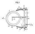
- Fig. 1 is a plan view showing the valve for a control muffler of the first embodiment
- Fig. 2 is a section view taken along the line S2-S2 and showing the valve for a control muffler of the first embodiment
- Fig. 3 is a section view showing main portions of the valve for a control muffler of the first embodiment.
- 1 denotes an inner pipe through which small chambers in a muffler are connected to each other
- 2 denotes a valve seat which is disposed at the downstream end of the inner pipe 1
- 3 denotes a valve element
- 31 denotes a main portion which closes and opens an opening of the valve seat 2
- 32 denotes a plate portion which elongates from one end of the main portion
- 33 denotes second shaft supporting portions which are formed by respectively raising the ends of the plate portion 32
- 4 denotes a bracket which elongates from one end of the valve seat 2
- 41 denotes a pair of right and left first shaft supporting portions which are formed on the bracket 4
- 5 denotes a support shaft which horizontally elongates between the first shaft supporting portions 41
- 6 denotes bushes (bearings) which are respectively interposed between the second shaft supporting portions 33 and the support shaft 5
- 7 denotes a torsion coil spring (urging member).
- a tapered seat portion 21 the diameter of which is gradually increased as moving toward the end is disposed in the valve seat 2.
- the inner face of the tapered seat portion 21 is configured as a tapered seat face 21a.
- a heat-resisting buffer seal member 22 is attached and fixed to the tapered seat face 21a.
- the heat-resisting seal member 22 is formed into an annular shape which is obtained by compressing stainless steel wire mesh into a mold, and then downward tapering the outer periphery of the compressed product.
- a tapered seal portion 31a which downward elongates in a tapered manner from the outer periphery of the main portion 31.
- the lower face of the tapered seal portion 31a is configured as a tapered seal face 31b which, when the valve element 3 is in the closing state, is in close contact with the heat-resisting buffer seal member 22 of the tapered seat face 21a, to seal the opening of the valve seat 2.
- a bush attaching portion 34 is formed by inward raising the peripheral edge of an opening by a burring process.
- the bushes 6 are partly attached to the bush attaching portions 34 in a press-fitted state, respectively.
- a shaft hole 41a through which the support shaft 5 can be passed through is opened in each of the shaft supporting portions 41.
- a welding rising portion (welding protrusion) 41b which is outward raised by a burring process is disposed in the peripheral edge of each of the shaft holes 41a.
- the ends of the support shaft 5 are passed through the shaft holes 41a of the shaft supporting portions 41, and welded and fixed to tip ends of the welding rising portions 41b, respectively.
- the reference numeral 8 denotes a weld metal.
- Each of the bushes 6 is formed by compressing stainless steel wire mesh into a mold, and configured by a cylindrical main portion 61 having a smaller diameter and a flange portion 62 having a larger diameter.
- a shaft hole 63 through which the support shaft 5 can be passed through is opened in the axial center of each bush.
- Each of the bushes is attached in a state where the cylindrical main portion 61 is pressingly inserted into the corresponding bush attaching portion 34 from the outside, and the flange portion 62 is interposed between the second shaft supporting portion 33 and the first shaft supporting portion 41.
- the torsion coil spring 7 is inserted onto the support shaft 5 to be supported thereby.
- the other end portion 72 abuts against the bracket 4 to urge the valve element 3 in the valve closing direction.
- the cylindrical main portions 61 of the bushes 6 are first pressingly inserted into the bush attaching portions 34 of the valve element 3 from the outside, respectively.
- the second shaft supporting portions 33 of the valve element 3 are placed inside the first shaft supporting portions 41 of the bracket 4, the torsion coil spring 7 is placed between the second shaft supporting portions 33, and the shaft holes 41a of the first shaft supporting portions 41 and the shaft holes 63 of the bushes 6 are aligned on a straight line.
- the support shaft 5 is passed through the shaft holes from the outside of one of the first shaft supporting portions 41, in the sequence of the shaft holes 41a, 63, 63, and 41a.
- the support shaft 5 is welded to the tip ends of the welding rising portions 41b to be fixed to the first shaft supporting portions 41.
- the first shaft supporting portions 41 to which the support shaft 5 is to be fixed are configured so that the welding rising portions 41b that are outward raised by a burring process are disposed in the shaft holes 41a through which the support shaft 5 is to be passed through, and the tip ends of the welding rising portions 41b are weldedly attached to the support shaft 5. Therefore, the welding points are located in positions separated from the bushes 6, so that, even when the weld metal 8 is moved via the shaft holes 41a by a certain distance toward the inner side of the valve element 3, the weld metal does not reach the flange portions 62 of the bushes 6, thereby attaining an effect that welding between the first shaft supporting portions 41 and the bushes 6 can be surely avoided.
- a valve for a control muffler of the embodiment corresponds to the second aspect of the invention.
- the components of the embodiment which are identical with those of the first embodiment are denoted by the same reference numerals as those used in the first embodiment, and their description is omitted.
- valve for a control muffler of the first embodiment a burring process is applied to the shaft holes 41a of the first shaft supporting portions 41 to dispose the welding rising portions 41b which outward protrude, in the peripheral edges of the openings, and the ends of the support shaft 5 are welded to the first shaft supporting portions 41, respectively.
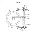
- the valve for a control muffler of the present embodiment is different from the first embodiment in that, as shown in Fig. 4, a burring process is applied only to the shaft hole 41a of the one first shaft supporting portion 41 to dispose the welding rising portion 41b, and only a shaft hole 91a is opened in the other first shaft supporting portion 91.
- the valve is different from the first embodiment also in that a squeezing process is applied to one end of a support shaft 10 to form an engagement portion 10a.
- the engagement portion 10a of the support shaft 10 abuts against the opening edge of the shaft hole 91a of the shaft supporting portion 91 on the insertion side, thereby attaining a state where the inward axial movement of the support shaft is blocked.
- the support shaft 10 is to be then welded and fixed to the first shaft supporting portion 41, therefore, the movement of the support shaft 10 in the axial direction is completely blocked by setting a state where the engagement portion 10a is upward directed, or pressing the engagement portion 10a toward the first shaft supporting portion 41 with fingers. Consequently, the support shaft 10 can be positioned easily and correctly, thereby attaining an effect that the workability of welding the support shaft 10 is improved.
- the welding protrusion may have any shape, and may be configured by disposing a protruding piece or the like on the opening edge of the shaft hole. Namely, it is requested only that the tip end which will be used as the welding position with respect to the support shaft is in the position separated from the shaft hole.
- both the ends of the support shaft are welded and fixed.
- only one end may be welded, and the other end may be subjected only to supporting.
- the support shaft on which a squeezing process is previously applied to form the engagement portion is used.
- a squeezing process may be applied to one end or both ends of the support shaft during an assembling process.
Landscapes
- Engineering & Computer Science (AREA)
- General Engineering & Computer Science (AREA)
- Mechanical Engineering (AREA)
- Chemical & Material Sciences (AREA)
- Combustion & Propulsion (AREA)
- Exhaust Silencers (AREA)
Abstract
Description
Claims (7)
- A valve for a control muffler the valve comprising:wherein the support shaft is welded to the welding protrusion;a valve seat placed in an open end of an exhaust pipe in the control muffler;a support shaft supported by shaft holes of a pair of first shaft supporting portions which are disposed in close proximity to the open end of the exhaust pipe;a valve element swingably journaled on the support shaft inside the pair of first shaft supporting portions;a pair of bearings respectively interposed between the support shaft and a pair of second shaft supporting portions that are disposed on the valve element to pivotally support the support shaft;an urging member for urging the valve element in a valve closing direction;a welding protrusion protruding in an axial direction, the welding protrusion disposed on an outer opening edge of the shaft hole of at least one of the pair of first shaft supporting portions,the urging member causes the valve element to maintain an abutting state with respect to the valve seat to close the exhaust pipe during a low engine speed period; andan exhaust gas pressure from the exhaust pipe causes the valve element to open the exhaust pipe during a high engine speed.
- The valve according to claim 1, wherein an engagement portion is disposed on a side of one end of the support shaft, the engagement portion abutting against the opening edge of the shaft hole of the first shaft supporting portion, to prevent the support shaft from being inward moved.
- A control muffler comprising:wherein the first shaft supporting portion has a welding protrusion protruding in an axial direction of the support shaft, the welding protrusion disposed on an outer opening edge of the shaft hole of the first shaft supporting portion.an exhaust pipe having an open end, the exhaust pipe having a valve seat placed in the open end of the exhaust pipe;a first shaft supporting portion disposed in close proximity to the open end of the exhaust pipe, the first shaft supporting portion defining a shaft hole;a support shaft supported by the shaft hole of the first shaft supporting portion; anda valve element swingably journaled on the support shaft inside the first shaft supporting portion;
- The control muffler as claimed in claim 3, further comprising:a second shaft supporting portion disposed on the valve element to pivotally support the support shaft;a bearing interposed between the support shaft and the second shaft supporting portion; andan urging member for urging the valve element to close the open end of the exhaust pipe.
- The control muffler as claimed in claim 4, wherein the support shaft is welded to the welding protrusion.
- The control muffler as claimed in claim 5, wherein the urging member causes the valve element to maintain an abutting state with respect to the valve seat to close the exhaust pipe during a low engine speed period; and
an exhaust gas pressure from the exhaust pipe causes the valve element to open the exhaust pipe during a high engine speed. - The valve according to claim 6, wherein an engagement portion is disposed on a side of one end of the support shaft, the engagement portion abutting against the opening edge of the shaft hole of the first shaft supporting portion, to prevent the support shaft from being inward moved.
Applications Claiming Priority (2)
| Application Number | Priority Date | Filing Date | Title |
|---|---|---|---|
| JP2000285319 | 2000-09-20 | ||
| JP2000285319A JP2002089256A (en) | 2000-09-20 | 2000-09-20 | Valve for control muffler |
Publications (3)
| Publication Number | Publication Date |
|---|---|
| EP1191194A2 true EP1191194A2 (en) | 2002-03-27 |
| EP1191194A3 EP1191194A3 (en) | 2003-11-26 |
| EP1191194B1 EP1191194B1 (en) | 2006-02-08 |
Family
ID=18769412
Family Applications (1)
| Application Number | Title | Priority Date | Filing Date |
|---|---|---|---|
| EP01122296A Expired - Lifetime EP1191194B1 (en) | 2000-09-20 | 2001-09-18 | Valve for a control muffler |
Country Status (4)
| Country | Link |
|---|---|
| US (1) | US6581721B2 (en) |
| EP (1) | EP1191194B1 (en) |
| JP (1) | JP2002089256A (en) |
| DE (1) | DE60117079T2 (en) |
Families Citing this family (35)
| Publication number | Priority date | Publication date | Assignee | Title |
|---|---|---|---|---|
| DE10311201A1 (en) * | 2003-03-14 | 2004-09-30 | Heinrich Gillet Gmbh | Silencer with variable damping characteristics |
| US7063182B2 (en) * | 2003-08-14 | 2006-06-20 | Arvinmeritor Technology, Llc | Muffler baffle plate spacer formed from stock material |
| US20050155816A1 (en) * | 2004-01-16 | 2005-07-21 | Alcini William V. | Dynamic exhaust system for advanced internal combustion engines |
| US7426979B2 (en) * | 2005-01-12 | 2008-09-23 | Calsonic Kansei Corporation | Exhaust gas control valve |
| US20070107981A1 (en) * | 2005-10-07 | 2007-05-17 | Sicotte Jason M | Exhaust silencer |
| JP4127292B2 (en) * | 2006-05-18 | 2008-07-30 | トヨタ自動車株式会社 | Muffler |
| JP4818872B2 (en) * | 2006-10-24 | 2011-11-16 | ヤマハ発動機株式会社 | Exhaust device for motorcycle and motorcycle equipped with the exhaust device |
| KR20080045558A (en) * | 2006-11-20 | 2008-05-23 | 삼성광주전자 주식회사 | Hermetic compressor |
| EP1939416B1 (en) * | 2006-12-29 | 2009-08-19 | Magneti Marelli S.p.A. | Variable geometry muffler fo an exhaust system of an internal combustion engine |
| KR101290212B1 (en) * | 2007-01-26 | 2013-07-31 | 포레시아 씨스뗌 데샤쁘망 | Valve for a motor vehicle exhaust silencer and silencer comprising a valve of this type |
| US7775322B2 (en) * | 2007-03-16 | 2010-08-17 | Tenneco Automotive Operating Company Inc. | Snap-action valve for exhaust system |
| US7434570B2 (en) * | 2007-03-16 | 2008-10-14 | Tenneco Automotive Operating Company Inc. | Snap-action valve for exhaust system |
| US7628250B2 (en) * | 2007-11-21 | 2009-12-08 | Emcon Technologies Llc | Passive valve assembly for vehicle exhaust system |
| JP4977903B2 (en) * | 2007-12-26 | 2012-07-18 | 本田技研工業株式会社 | Exhaust valve control device |
| US20100025146A1 (en) * | 2008-07-31 | 2010-02-04 | Shu-Li Ho | Baffle plate operating mechanism for muffler |
| US8191572B2 (en) * | 2009-04-16 | 2012-06-05 | Tenneco Automotive Operating Company Inc. | Snap action valve with bumper pad |
| US7896130B2 (en) * | 2009-05-22 | 2011-03-01 | Tenneco Automotive Operating Company Inc. | Snap action valve with inertia damper |
| US7938227B2 (en) * | 2009-10-06 | 2011-05-10 | Honda Motor Co., Ltd. | Variable resonation chamber valve |
| IT1396950B1 (en) | 2009-12-17 | 2012-12-20 | Ohg Giuseppe Lafranconi S P A | MOUNTING OF A BUTTERFLY VALVE IN A GAS OUTLET OF AN INTERNAL COMBUSTION ENGINE |
| US8353153B2 (en) * | 2010-02-25 | 2013-01-15 | Tenneco Automotive Operating Company Inc. | Snapper valve for hot end systems with burners |
| DE102012107840B4 (en) * | 2012-08-24 | 2014-05-28 | Eberspächer Exhaust Technology GmbH & Co. KG | Change-over valve and method for producing the same |
| KR20140073979A (en) * | 2012-12-07 | 2014-06-17 | 현대자동차주식회사 | Variable valve for exhaust pipe |
| KR20140077039A (en) * | 2012-12-13 | 2014-06-23 | 현대자동차주식회사 | Variable valve appratus and muffler provided with the same |
| US8657065B1 (en) * | 2012-12-14 | 2014-02-25 | Tenneco Automotive Operating Company Inc. | Exhaust valve with resilient spring pad |
| JP6291079B2 (en) * | 2014-11-10 | 2018-03-14 | フタバ産業株式会社 | Switching valve |
| JP6290812B2 (en) * | 2015-03-26 | 2018-03-07 | 本田技研工業株式会社 | Silencer |
| DE102015110199A1 (en) * | 2015-06-25 | 2016-12-29 | Eberspächer Exhaust Technology GmbH & Co. KG | exhaust silencer |
| KR101709706B1 (en) * | 2015-10-14 | 2017-02-23 | 우신공업 주식회사 | Exhaust valve for muffler and muffler including the same |
| WO2017079156A1 (en) * | 2015-11-02 | 2017-05-11 | Roush Enterprises, Inc. | Muffler with selected exhaust pathways |
| CN105781679A (en) * | 2016-05-17 | 2016-07-20 | 上海天纳克排气系统有限公司 | Partition plate for muffler and muffler for baffle |
| US9982794B2 (en) | 2016-08-05 | 2018-05-29 | Tenneco Automotive Operating Company Inc. | Passive exhaust valve with external torsion spring |
| US9982793B2 (en) * | 2016-08-05 | 2018-05-29 | Tenneco Automotive Operating Company Inc. | Passive exhaust valve with dual torsion spring |
| CN107989774A (en) * | 2017-12-11 | 2018-05-04 | 青岛海尔股份有限公司 | Vacuum pump discharges pipe muffler and refrigerator |
| KR102148410B1 (en) * | 2018-07-06 | 2020-08-26 | 포레시아코리아 유한회사 | Valve assembly for vehicle exhaust system |
| JP7728145B2 (en) * | 2021-10-26 | 2025-08-22 | 日本発條株式会社 | Vehicle seat frame and vehicle seat |
Family Cites Families (12)
| Publication number | Priority date | Publication date | Assignee | Title |
|---|---|---|---|---|
| US3620330A (en) * | 1969-04-14 | 1971-11-16 | Oldberg Mfg Co | Muffler construction and method of selectively modifying its sound-attenuating characteristics |
| GB1323686A (en) * | 1969-11-26 | 1973-07-18 | Secr Defence | Welding |
| US4607977A (en) * | 1985-08-05 | 1986-08-26 | Varnelis Edmund K | Pivot joint |
| NZ240672A (en) * | 1991-12-04 | 1995-10-26 | Graeme Charles Stephens | Muffler with valve controlled through passage |
| WO1995013460A1 (en) * | 1993-11-09 | 1995-05-18 | Futaba Industrial Co., Ltd. | Muffler for an internal combustion engine |
| US5614699A (en) * | 1994-05-09 | 1997-03-25 | Nissan Motor Co., Ltd. | Automobile exhaust noise suppressor |
| JP3379254B2 (en) * | 1994-12-26 | 2003-02-24 | 日産自動車株式会社 | Exhaust silencer |
| US5984045A (en) * | 1997-02-14 | 1999-11-16 | Nissan Motor Co., Ltd. | Engine exhaust noise suppressor |
| JP4008101B2 (en) * | 1998-05-06 | 2007-11-14 | カルソニックカンセイ株式会社 | Exhaust system valve body assembly method and exhaust system valve |
| DE69902085T2 (en) * | 1999-02-18 | 2003-01-30 | Hyundai Motor Co., Seoul/Soul | Semi-active silencer for internal combustion engines |
| JP2002089257A (en) * | 2000-09-11 | 2002-03-27 | Calsonic Kansei Corp | Control muffler valve and valve assembly method for control muffler valve |
| JP2002106323A (en) * | 2000-09-28 | 2002-04-10 | Calsonic Kansei Corp | Valve for control muffler |
-
2000
- 2000-09-20 JP JP2000285319A patent/JP2002089256A/en active Pending
-
2001
- 2001-09-18 DE DE60117079T patent/DE60117079T2/en not_active Expired - Lifetime
- 2001-09-18 EP EP01122296A patent/EP1191194B1/en not_active Expired - Lifetime
- 2001-09-20 US US09/955,952 patent/US6581721B2/en not_active Expired - Fee Related
Also Published As
| Publication number | Publication date |
|---|---|
| US6581721B2 (en) | 2003-06-24 |
| US20020033303A1 (en) | 2002-03-21 |
| DE60117079T2 (en) | 2006-07-20 |
| JP2002089256A (en) | 2002-03-27 |
| EP1191194B1 (en) | 2006-02-08 |
| EP1191194A3 (en) | 2003-11-26 |
| DE60117079D1 (en) | 2006-04-20 |
Similar Documents
| Publication | Publication Date | Title |
|---|---|---|
| US6581721B2 (en) | Valve for a control muffler | |
| EP1231362B1 (en) | Valve structure for engine exhaust system | |
| US10487725B2 (en) | Variable flow valve mechanism and turbocharger | |
| US5401001A (en) | Internal combustion engine exhaust control valve | |
| EP1186756B1 (en) | Pressure sensible valve for exhaust muffler and method of assembling same | |
| US20060260868A1 (en) | Exhaust flow rate control valve | |
| JP6269842B2 (en) | Variable flow rate valve mechanism and turbocharger | |
| EP1408206B1 (en) | Valve device for silencer | |
| WO2018034891A1 (en) | Flutter dampened exhaust valve | |
| WO2018034888A1 (en) | Slotted snap-action valve assembly for exhaust system | |
| JP2016050525A (en) | Variable flow rate valve mechanism and turbocharger | |
| JPWO2020008697A1 (en) | Variable flow valve mechanism and turbocharger | |
| US11274581B2 (en) | Externally mounted in-line exhaust gas valve | |
| US10746091B2 (en) | Turbocharger that is configured to direct exhaust gas away from a contact surface | |
| EP1939416B1 (en) | Variable geometry muffler fo an exhaust system of an internal combustion engine | |
| JP2002106323A (en) | Valve for control muffler | |
| US20230193796A1 (en) | Muffler valve and muffler | |
| KR101320979B1 (en) | Muffler | |
| EP2003313B1 (en) | Exhaust pressure control valve | |
| JP2012036887A (en) | Exhaust control valve | |
| JPH116417A (en) | Automotive exhaust silencer | |
| US12007043B2 (en) | Valve structure and turbocharger | |
| JP2002097949A (en) | Valve for control muffler | |
| JPH07310837A (en) | Swing check valve | |
| JP2020002782A (en) | Valve manufacturing method for valve device and valve structure |
Legal Events
| Date | Code | Title | Description |
|---|---|---|---|
| PUAI | Public reference made under article 153(3) epc to a published international application that has entered the european phase |
Free format text: ORIGINAL CODE: 0009012 |
|
| AK | Designated contracting states |
Kind code of ref document: A2 Designated state(s): AT BE CH CY DE DK ES FI FR GB GR IE IT LI LU MC NL PT SE TR |
|
| AX | Request for extension of the european patent |
Free format text: AL;LT;LV;MK;RO;SI |
|
| PUAL | Search report despatched |
Free format text: ORIGINAL CODE: 0009013 |
|
| AK | Designated contracting states |
Kind code of ref document: A3 Designated state(s): AT BE CH CY DE DK ES FI FR GB GR IE IT LI LU MC NL PT SE TR |
|
| AX | Request for extension of the european patent |
Extension state: AL LT LV MK RO SI |
|
| RIC1 | Information provided on ipc code assigned before grant |
Ipc: 7F 01N 1/08 B Ipc: 7F 01N 1/16 A |
|
| 17P | Request for examination filed |
Effective date: 20040204 |
|
| 17Q | First examination report despatched |
Effective date: 20040414 |
|
| AKX | Designation fees paid |
Designated state(s): DE FR GB |
|
| GRAP | Despatch of communication of intention to grant a patent |
Free format text: ORIGINAL CODE: EPIDOSNIGR1 |
|
| GRAS | Grant fee paid |
Free format text: ORIGINAL CODE: EPIDOSNIGR3 |
|
| GRAA | (expected) grant |
Free format text: ORIGINAL CODE: 0009210 |
|
| AK | Designated contracting states |
Kind code of ref document: B1 Designated state(s): DE FR GB |
|
| REG | Reference to a national code |
Ref country code: GB Ref legal event code: FG4D |
|
| REF | Corresponds to: |
Ref document number: 60117079 Country of ref document: DE Date of ref document: 20060420 Kind code of ref document: P |
|
| ET | Fr: translation filed | ||
| PLBE | No opposition filed within time limit |
Free format text: ORIGINAL CODE: 0009261 |
|
| STAA | Information on the status of an ep patent application or granted ep patent |
Free format text: STATUS: NO OPPOSITION FILED WITHIN TIME LIMIT |
|
| 26N | No opposition filed |
Effective date: 20061109 |
|
| PGFP | Annual fee paid to national office [announced via postgrant information from national office to epo] |
Ref country code: GB Payment date: 20090916 Year of fee payment: 9 |
|
| PGFP | Annual fee paid to national office [announced via postgrant information from national office to epo] |
Ref country code: DE Payment date: 20090910 Year of fee payment: 9 |
|
| PGFP | Annual fee paid to national office [announced via postgrant information from national office to epo] |
Ref country code: FR Payment date: 20091012 Year of fee payment: 9 |
|
| GBPC | Gb: european patent ceased through non-payment of renewal fee |
Effective date: 20100918 |
|
| REG | Reference to a national code |
Ref country code: FR Ref legal event code: ST Effective date: 20110531 |
|
| REG | Reference to a national code |
Ref country code: DE Ref legal event code: R119 Ref document number: 60117079 Country of ref document: DE Effective date: 20110401 |
|
| PG25 | Lapsed in a contracting state [announced via postgrant information from national office to epo] |
Ref country code: DE Free format text: LAPSE BECAUSE OF NON-PAYMENT OF DUE FEES Effective date: 20110401 Ref country code: FR Free format text: LAPSE BECAUSE OF NON-PAYMENT OF DUE FEES Effective date: 20100930 |
|
| PG25 | Lapsed in a contracting state [announced via postgrant information from national office to epo] |
Ref country code: GB Free format text: LAPSE BECAUSE OF NON-PAYMENT OF DUE FEES Effective date: 20100918 |