EP1190940A1 - A support device for a spare wheel of a vehicle, provided with a lever for the lateral positioning of said wheel - Google Patents
A support device for a spare wheel of a vehicle, provided with a lever for the lateral positioning of said wheel Download PDFInfo
- Publication number
- EP1190940A1 EP1190940A1 EP01122886A EP01122886A EP1190940A1 EP 1190940 A1 EP1190940 A1 EP 1190940A1 EP 01122886 A EP01122886 A EP 01122886A EP 01122886 A EP01122886 A EP 01122886A EP 1190940 A1 EP1190940 A1 EP 1190940A1
- Authority
- EP
- European Patent Office
- Prior art keywords
- support
- frame
- wheel
- lever
- spare wheel
- Prior art date
- Legal status (The legal status is an assumption and is not a legal conclusion. Google has not performed a legal analysis and makes no representation as to the accuracy of the status listed.)
- Granted
Links
- 238000006073 displacement reaction Methods 0.000 claims abstract description 5
- 230000003993 interaction Effects 0.000 claims description 3
- 230000008878 coupling Effects 0.000 description 15
- 238000010168 coupling process Methods 0.000 description 15
- 238000005859 coupling reaction Methods 0.000 description 15
- 230000000712 assembly Effects 0.000 description 9
- 238000000429 assembly Methods 0.000 description 9
- 238000004873 anchoring Methods 0.000 description 3
- 230000009471 action Effects 0.000 description 2
- 239000013536 elastomeric material Substances 0.000 description 1
- 230000005484 gravity Effects 0.000 description 1
- 230000004048 modification Effects 0.000 description 1
- 238000012986 modification Methods 0.000 description 1
- 230000002093 peripheral effect Effects 0.000 description 1
Images


Classifications
-
- B—PERFORMING OPERATIONS; TRANSPORTING
- B62—LAND VEHICLES FOR TRAVELLING OTHERWISE THAN ON RAILS
- B62D—MOTOR VEHICLES; TRAILERS
- B62D43/00—Spare wheel stowing, holding, or mounting arrangements
- B62D43/02—Spare wheel stowing, holding, or mounting arrangements external to the vehicle body
- B62D43/04—Spare wheel stowing, holding, or mounting arrangements external to the vehicle body attached beneath the vehicle body
Definitions
- the present invention relates to a support device for a spare wheel of a vehicle, particularly but not exclusively of a commercial vehicle.
- Devices of the above-mentioned type which substantially comprise a support on which the spare wheel is secured in operation, for example by means of bolts, connecting means connecting the support to a frame of the vehicle so as to be movable between a rest position and a removal position for the withdrawal of said wheel, and releasable fastening means, generally of the screw and nut type, for fastening the support to the frame in the rest position.
- the connecting means may comprise hinge-type elements for the direct connection of one end of the support to the frame, or by guide elements secured or hinged to said frame and engaged in a sliding manner by respective rollers of the support.
- the spare wheel In the rest position of the support, the spare wheel is generally locked in a vertical direction, exerting tension on the fastening means, and in a horizontal direction causing the tyre of the wheel to abut against abutment means attached to the frame.
- the spare wheel is partly or wholly deflated (punctured wheel)
- the locking of said wheel in the vertical direction does not pose any problem insofar as it is merely necessary to increase the tension on the releasable fastening means; on the other hand, it may happen that the partly deflated tyre does not abut satisfactorily against the associated abutment means, with the result that vibration occurs when the vehicle is motion.
- the object of the present invention is to devise a support device for a spare wheel of a vehicle, which makes it possible to obviate the disadvantage associated with the above-mentioned known devices.
- This object is achieved by the present invention in that it relates to a support assembly for a spare wheel of a vehicle, in particular a commercial vehicle, comprising
- the reference numeral 1 generally denotes a support device for a spare wheel 2 of a commercial vehicle, known per se and not shown as a whole, said spare wheel having an axis A.
- said commercial vehicle is provided with a frame 3, of which the accompanying drawings show the component parts necessary for an understanding of the present invention.
- the wheel 2 comprises a rim 4, having an axis A, defining a central hole 4a adapted to be engaged by an associated wheel hub (not shown) of the vehicle, and by a tyre 6 mounted conventionally on a peripheral flange 5 of the rim 4 itself.
- the support device 1 essentially comprises a guide assembly 7 connected to the frame 3 so as to be able to rotate about a horizontal axis B, between a raised position and a lowered position, and defining with said frame 3 a compartment 8 for accommodating the wheel 2 situated low down with respect to the vehicle, a trolley 9 carrying the wheel 2 in a releasable manner and mounted to slide along the guide assembly 7 between a rest position inside the compartment 8 ( Figures 1 and 2) and a removal position ( Figure 1, dashed line), in which it is partly removed from the compartment 8 so as to allow the withdrawal of said wheel 2, and releasable fastening means 10 acting in an approximately vertical connecting direction C and in a position spaced apart from the axis B so as to fasten jointly to the frame 3 the guide assembly 7 in the raised position and the trolley 9 in the rest position.
- the guide assembly 7 defines a handling path of the trolley 9 between the rest and withdrawal positions resulting from a combination of movements in a vertical direction S and in a horizontal direction T; as is evident from Figures 1,4 and 5, the connecting direction C is slightly inclined relative to the vertical direction S.
- the guide assembly 7 comprises a pair of guide sections 11 extending parallel to one another and each having corresponding ends 12 hinged about the axis B to respective brackets 13 projecting downwards from associated side members 14 of the frame 3.
- the guide sections 11 are connected to one another, with their ends 15 opposite the ends 12 in alignment, by a cross member (not shown in the accompanying drawings) and they can rotate about the axis B between the aforementioned raised and lowered positions. In particular, in the lowered position, adjacent the ground, the guide sections 11 allow the trolley 9 to slide between the rest position and the removal position.
- each guide section 11 is of "skid" shape and comprises two straight portions 17,18 which between them define an obtuse angle of less than 180o and are joined by a curved connecting portion 19; in particular, the portion 17 extends from the associated hinge bracket 13 and is of shorter length than the length of the portion 18.
- the guide sections 11 define respective longitudinal guide cavities 20 which are closed with the ends 15 in alignment by respective removable stops 21 ( Figures 3 and 5) and which are of C-shaped cross-section with facing concavities.
- respective bumpers 28 of elastomeric material project from the ends 15 of the guide sections 11 and are adapted to co-operate by abutting against associated portions of the frame 3 in the raised position of said guide sections 11.
- the trolley 9 comprises a plurality of bars which are welded to one another so as form a substantially flat structure on which the wheel 2 can be mounted with its axis A substantially orthogonal to the plane in which said trolley 9 lies.
- the trolley 9 comprises a substantially U-shaped section member 22 having a pair of arms 23 extending orthogonally from respective opposite ends of a substantially straight operating bar 24 which, in operation, is intended to define a grip or handle portion for the handling of said trolley 9.
- the trolley 9 comprises a pair of cross members 25,26 which are secured orthogonally to the arms 23, which project laterally from said arms 23 and which are provided, in alignment with portions thereof at opposite ends, with respective idle rollers 27 adapted to engage in pairs in the associated cavities 20 formed by the guide sections 11. More precisely, the cross member 25 extends in alignment with respective free ends of the arms 23, whereas the cross member 26 extends in an intermediate position between the bar 24 and said cross member 25.
- the trolley 9 comprises a plate 30 of substantially quadrangular section, the opposite end edges of which are secured to the respective arms 23 and extend parallel to the cross members 25,26 and in an intermediate position between them.
- a nut 31 and a tubular centering peg 32 are secured to a central portion of the plate 30 and project therefrom on opposite sides, which peg can engage in the hole 4a of the rim 4 of the wheel 2.
- the nut 31 and the peg 32 are coaxial to one another and to a through-hole (not shown in the accompanying drawings) of the plate 30 and are adapted to be engaged, together with said through-hole, by a closing screw 33 for fastening the wheel 2 to the trolley 9.
- the compartment 8 is bounded by the side members 14 of the frame 3, by the guide sections 11 and by a series of abutment assemblies for the wheel 2 attached to said side members 14.
- said abutment assemblies comprise a pair of disc-like supports 34 upwardly defining the compartment 8, and a shaped structure 35 defining the bottom of said compartment 8.
- the supports 34 are suspended from respective L-shaped supports 36 projecting orthogonally towards one another from the associated side members 14, starting from the extension zone of the brackets 13.
- the structure 35 comprises a cross member 37 secured between respective lower end portions of the brackets 13, and an upright 38 extending upwards from a central portion of the cross member 37 and of C-shaped section in side view ( Figures 1 and 4) for receiving the tread 6a of the tyre 6 of the wheel 2 and part of respective side walls 6b of said tyre 6.
- the fastening means 10 comprise two connecting assemblies 40 adapted to connect a horizontal cross member 39 extending between the side members 14, with respective arms 23 of the trolley 9 in a position adjacent to the operating bar 24; in particular, the cross member 39 has an axis D parallel to the axis A and orthogonal to the side members 14.
- Each connecting assembly 40 comprises a receiving member 41 projecting from the associated arm 23 of the trolley 9 towards the adjacent guide section 11 and defining a C-shaped seating 42 with its concavity turned towards said guide section 11, and a coupling element 43 which is suspended from the cross-member 39 so as to swing in a direction E transverse to the direction C and substantially parallel to the axis D, and it can be displaced in said direction E towards and from a coupling configuration with the seating 42 of the associated receiving element 41.
- each seating 42 has its concavity facing in the direction E.
- Each receiving element 41 projects from an end portion 44 of the associated arm 23 adjacent the operating bar 24 and comprises an anchoring portion 45 welded to the end portion 44 and a pair of projections 46 protruding from the anchoring portion 45 towards the adjacent guide section 11 and defining between one another and with said anchoring portion the seating 42.
- each receiving element 41 has a C-shaped raised upper edge 47 covering the outer periphery of the associated seating 42 and defining an upper opening 48 from which said seating 42 extends downwards with gradually increasing section.
- Each coupling element 43 is of elongate shape and is provided, in the vicinity of the lower end thereof, with an annular enlargement 50 adapted to be inserted inside the seating 42 of the associated receiving element 41 abutting upwardly against the edge 47 so as to prevent downward movement of the trolley 9 and the guide assembly 7.
- Each coupling element 43 comprises a shaped tie rod 51 having a cylindrical outer surface, which tie rod is connected in its upper region to the cross member 39 and which has in its lower region an externally threaded portion 52 and an internally threaded cylindrical sleeve 53, screwed on to the portion 52 of the tie rod 51 and integrally defining, level with its lower end, the enlargement 50.
- each tie rod 51 has an upper end portion 54 bent downwards to define an inverted U-section and engaging in a through-hole in a bracket 55 attached to the cross-member 39.
- the sleeves 53 When they are coupled to the seatings 42 of the receiving elements 41, the sleeves 53 can be screwed on to the associated tie rods 51 so as to exert tension on the connecting assemblies 40 and prevent any danger of accidental uncoupling of said coupling elements 43 and said receiving elements 41. With a view to enabling the sleeves 53 to be screwed and unscrewed along the respective tie rods 51, at their lower end they terminate in respective nuts 57 which can be operated by a spanner.
- each guide section 11 can be connected to the associated side member 14 by means of a safety hook 66.
- the support device 1 further comprises a lever 60 for correctly positioning the assembly formed by the trolley 9 and by the wheel 2 inside the compartment 8.
- the lever 60 is disposed upwardly with respect to the trolley 9 and in a position opposite the structure 35 defining the bottom of the compartment 8; it is hinged about the axis D of the cross member 39 and it can co-operate with the wheel 2 on the side diametrically opposite said structure 35.
- the lever 60 has a hollow intermediate portion 61 engaged by the cross member 39 and positioned between the connecting assemblies 40, an operating arm 62 adapted to co-operate with the rim 4 of the wheel 2 so as to receive therefrom, in the stage in which the trolley 9 is being raised so as to connect it to the cross member 39 by means of the connecting assemblies 40, thrust forces tending to rotate said operating arm 62 about the axis D and a pressing arm 63 adapted to co-operate with the tread 6a of the tyre 6 so as to press the wheel 2 into abutment with the structure 35 under the action of the rotation of the operating arm 62.
- the operating and pressing arms 62,63 project from the intermediate portion 61 substantially in directions orthogonal to one another.
- the operating arm 62 comprises a shaped plate which has a flat first portion 64 adjacent the intermediate portion 61 and adapted to form an upper abutment for the side wall 6b of the tyre 6 of the wheel 2 opposite that arranged in contact with the trolley 9, and a second portion 65 which is also flat and bent towards the trolley 9, i.e. downwards with respect to the portion 64, and which is adapted to co-operate with the rim 4 of the wheel 2 in the vicinity of the flange 5.
- the pressing arm 63 comprises a flat plate substantially orthogonal to the portion 64 of the operating arm 62 and extending downwards from the intermediate portion 61 with respect to the overall extension of the operating arm 62 from said intermediate portion 61.
- the lever 60 In the absence of load, i.e. interaction with the wheel 2, the lever 60 is arranged under the action of its own weight, which is greater along the operating arm 62, in a first operating position ( Figure 4) in which said operating arm 62 is oblique with respect to the vertical direction S and extending downwards from the intermediate portion 61. In this position the rim 4 of the wheel 2 can be engaged more easily by the portion 65 of the operating arm 62 when the trolley 9 is being displaced from the removal position into the rest position.
- the lever 60 reaches a second operating position ( Figures 1,2 and 5), in which the operating arm 62 extends substantially in the horizontal direction T and the pressing arm 63 extends substantially in the vertical direction S.
- said operating positions of the lever 60 are defined by the abutment of a pin 67 attached to the cross member 39 with respective opposite end edges of a slot 68 provided in the intermediate portion 61 of said lever 60.
- the guide sections 11 are arranged in the raised position and they are connected by means of the safety hooks 66 to the respective side members 14, whereas the trolley 9 is arranged in the rest position on the guide sections 11 and it is fastened to the cross member 39 of the frame 3 by means of the connecting assemblies 40.
- the wheel 2, which is concealed in the compartment 8, is clamped substantially in the vertical direction S between the supports 34 and the operating arm 62 of the lever 60 on the one hand, and the guide sections 11 and the trolley 9 on the other hand. Moreover, the wheel 2 is locked laterally between the lever 60 and the structure 35 of the frame 3.
- the safety hooks 66 are uncoupled from the respective guide sections 11 and the split pins 56 are withdrawn from the respective coupling elements 43.
- the guide sections 11 can then rotate about the axis B until reaching the lowered position and the trolley 9 can slide along said sections 11 from the rest position into the removal position ( Figure 1, dashed line), in which it is partly removed from the compartment 8 and it projects outwardly with the respect to the vehicle so as to allow the wheel 2 to be withdrawn.
- the wheel 2 can be freed from the trolley 9 by acting on the screw 33 or the trolley 9 and the wheel 2 can be uncoupled from the guide sections 11 by removing the end stops 21.
- the mounting of the trolley 9 on the vehicle takes place substantially by repeating the above-described sequence of operations in reverse order.
- the trolley 9 provided with a replacement wheel or with the spare wheel 2 is caused to slide on the guide sections 11 from the removal position towards the rest and raised position, holding it with the operating bar 24, towards the side members 14.
- each coupling element 43 When the receiving elements 41 are aligned horizontally with the enlargements 50 of the respective coupling elements 43, the latter are displaced in opposite directions in the direction E until reaching the coupling configuration with said receiving elements 41. More precisely, the enlargement 50 of each coupling element 43 is inserted in the direction E into the seating 42 of the associated receiving element 41 abutting upwardly against the edge 47.
- the rim 4 of the wheel 2 upwardly comes into contact with the free end of the operating arm 62 of the lever 60 causing it to rotate about the axis D in a clockwise direction with reference to the accompanying drawings.
- the operating arm 62 receives from the rim 4 an actuating force in the vertical direction S.
- the rotation of the operating arm 62 brings about a corresponding angular displacement about the axis D of the pressing arm 63 which interacts with the tread 6a of the wheel 2 by pressing said wheel 2 in the horizontal direction T into abutment with the opposing structure 35.
- the arrangement of the lever 60 which is actuated by the raising of the rim 4 of the wheel 2, ensures the correct positioning and locking of said wheel 2 in the horizontal direction T against the abutment structure 35, whatever the state of inflation of the tyre 6. It is evident that the support device 1 can be subject to modifications and variants which do not depart from the scope of protection defined by the claims.
Landscapes
- Engineering & Computer Science (AREA)
- Chemical & Material Sciences (AREA)
- Combustion & Propulsion (AREA)
- Transportation (AREA)
- Mechanical Engineering (AREA)
- Body Structure For Vehicles (AREA)
- Handcart (AREA)
- Automobile Manufacture Line, Endless Track Vehicle, Trailer (AREA)
- Eye Examination Apparatus (AREA)
- Air Bags (AREA)
Abstract
Description
- The present invention relates to a support device for a spare wheel of a vehicle, particularly but not exclusively of a commercial vehicle.
- Devices of the above-mentioned type are known, which substantially comprise a support on which the spare wheel is secured in operation, for example by means of bolts, connecting means connecting the support to a frame of the vehicle so as to be movable between a rest position and a removal position for the withdrawal of said wheel, and releasable fastening means, generally of the screw and nut type, for fastening the support to the frame in the rest position.
- The connecting means may comprise hinge-type elements for the direct connection of one end of the support to the frame, or by guide elements secured or hinged to said frame and engaged in a sliding manner by respective rollers of the support.
- In the rest position of the support, the spare wheel is generally locked in a vertical direction, exerting tension on the fastening means, and in a horizontal direction causing the tyre of the wheel to abut against abutment means attached to the frame.
- In the event that the spare wheel is partly or wholly deflated (punctured wheel), the locking of said wheel in the vertical direction does not pose any problem insofar as it is merely necessary to increase the tension on the releasable fastening means; on the other hand, it may happen that the partly deflated tyre does not abut satisfactorily against the associated abutment means, with the result that vibration occurs when the vehicle is motion.
- The object of the present invention is to devise a support device for a spare wheel of a vehicle, which makes it possible to obviate the disadvantage associated with the above-mentioned known devices.
- This object is achieved by the present invention in that it relates to a support assembly for a spare wheel of a vehicle, in particular a commercial vehicle, comprising
- a support adapted to carry said spare wheel in a releasable manner;
- connecting means connecting said support to a frame of said vehicle so as to be movable between a rest position and a removal position for the withdrawal of said spare wheel, and defining a handling path of said support arising from a combination of movements in a first direction and a second direction which are mutually transverse; and
- releasable fastening means for fastening said support to the frame in the rest position and for clamping said spare wheel substantially in said first direction between said support and said frame;
- With a view to a better understanding of the present invention a preferred embodiment will be described non-restrictively by way of example below, with reference to the accompanying drawings, in which:
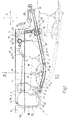
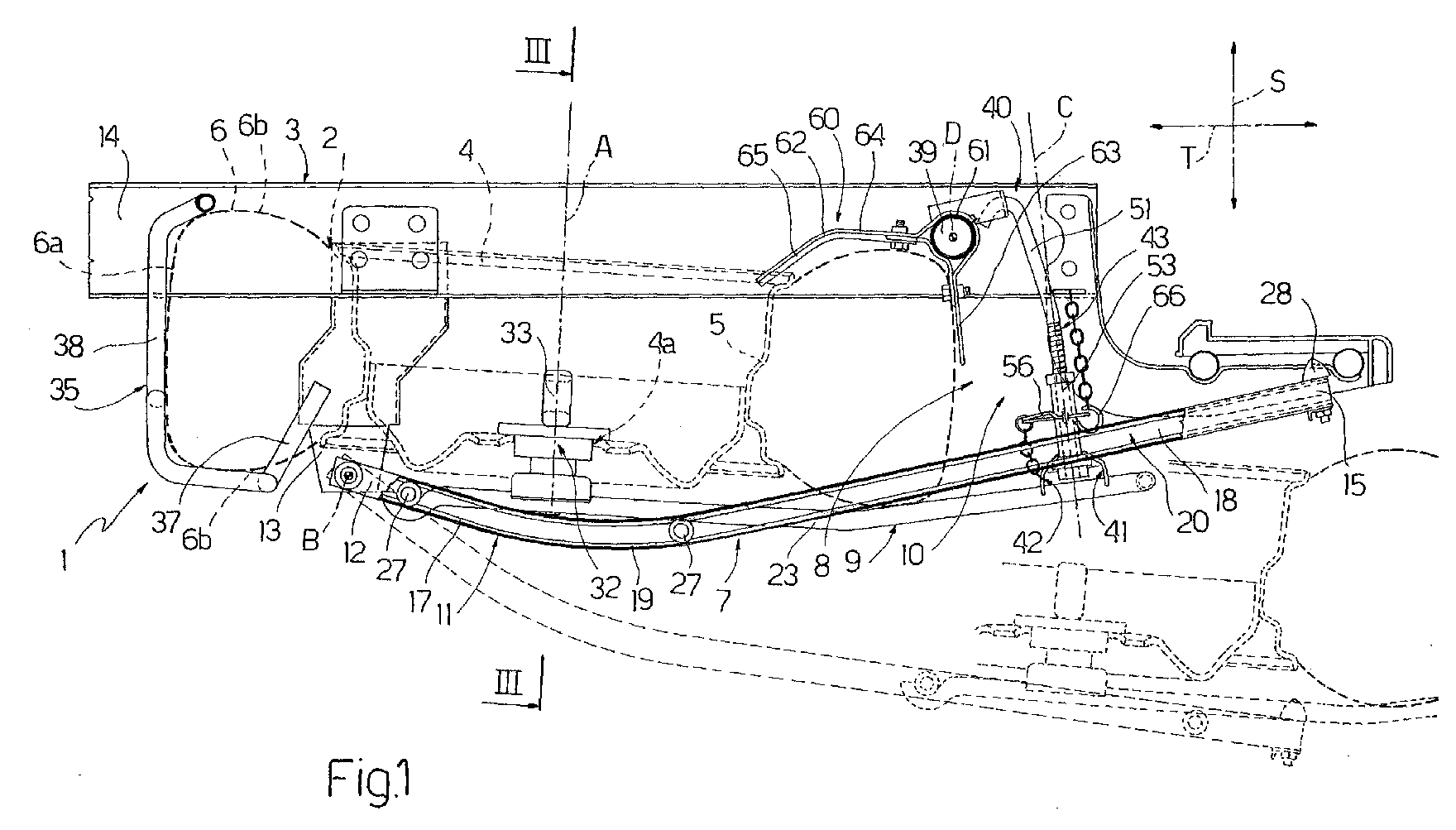
- Figure 1 is side view of a support device for a spare wheel of a vehicle, in accordance with the present invention;
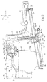
- Figure 2 is a view from above, on a reduced scale, of the support device in Figure 1;
- Figure 3 is a partial section, on an enlarged scale, along the line III-III in Figure 1;
- Figure 4 is a side view of the support device in Figure 1, in a different operating position; and
- Figure 5 is a side view, on an enlarged scale and partly in section, of a detail of the support device in Figure 1.
-
- Referring now to Figures 1 to 4, the
reference numeral 1 generally denotes a support device for aspare wheel 2 of a commercial vehicle, known per se and not shown as a whole, said spare wheel having an axis A. In particular, said commercial vehicle is provided with aframe 3, of which the accompanying drawings show the component parts necessary for an understanding of the present invention. - As is known, the
wheel 2 comprises arim 4, having an axis A, defining acentral hole 4a adapted to be engaged by an associated wheel hub (not shown) of the vehicle, and by atyre 6 mounted conventionally on aperipheral flange 5 of therim 4 itself. - Referring now to Figures 1,2 and 4, the
support device 1 essentially comprises aguide assembly 7 connected to theframe 3 so as to be able to rotate about a horizontal axis B, between a raised position and a lowered position, and defining with said frame 3 acompartment 8 for accommodating thewheel 2 situated low down with respect to the vehicle, atrolley 9 carrying thewheel 2 in a releasable manner and mounted to slide along theguide assembly 7 between a rest position inside the compartment 8 (Figures 1 and 2) and a removal position (Figure 1, dashed line), in which it is partly removed from thecompartment 8 so as to allow the withdrawal of saidwheel 2, and releasable fastening means 10 acting in an approximately vertical connecting direction C and in a position spaced apart from the axis B so as to fasten jointly to theframe 3 theguide assembly 7 in the raised position and thetrolley 9 in the rest position. Theguide assembly 7 defines a handling path of thetrolley 9 between the rest and withdrawal positions resulting from a combination of movements in a vertical direction S and in a horizontal direction T; as is evident from Figures 1,4 and 5, the connecting direction C is slightly inclined relative to the vertical direction S. - In particular, the
guide assembly 7 comprises a pair ofguide sections 11 extending parallel to one another and each havingcorresponding ends 12 hinged about the axis B torespective brackets 13 projecting downwards from associatedside members 14 of theframe 3. Theguide sections 11 are connected to one another, with theirends 15 opposite theends 12 in alignment, by a cross member (not shown in the accompanying drawings) and they can rotate about the axis B between the aforementioned raised and lowered positions. In particular, in the lowered position, adjacent the ground, theguide sections 11 allow thetrolley 9 to slide between the rest position and the removal position. - In side view, each
guide section 11 is of "skid" shape and comprises twostraight portions portion 19; in particular, theportion 17 extends from the associatedhinge bracket 13 and is of shorter length than the length of theportion 18. - The
guide sections 11 define respectivelongitudinal guide cavities 20 which are closed with theends 15 in alignment by respective removable stops 21 (Figures 3 and 5) and which are of C-shaped cross-section with facing concavities. In addition,respective bumpers 28 of elastomeric material project from theends 15 of theguide sections 11 and are adapted to co-operate by abutting against associated portions of theframe 3 in the raised position of saidguide sections 11. - Referring particularly to Figure 2, the
trolley 9 comprises a plurality of bars which are welded to one another so as form a substantially flat structure on which thewheel 2 can be mounted with its axis A substantially orthogonal to the plane in which saidtrolley 9 lies. - In particular, the
trolley 9 comprises a substantially U-shapedsection member 22 having a pair ofarms 23 extending orthogonally from respective opposite ends of a substantiallystraight operating bar 24 which, in operation, is intended to define a grip or handle portion for the handling of saidtrolley 9. Furthermore, thetrolley 9 comprises a pair ofcross members arms 23, which project laterally fromsaid arms 23 and which are provided, in alignment with portions thereof at opposite ends, withrespective idle rollers 27 adapted to engage in pairs in the associatedcavities 20 formed by theguide sections 11. More precisely, thecross member 25 extends in alignment with respective free ends of thearms 23, whereas thecross member 26 extends in an intermediate position between thebar 24 and saidcross member 25. - Finally, the
trolley 9 comprises aplate 30 of substantially quadrangular section, the opposite end edges of which are secured to therespective arms 23 and extend parallel to thecross members nut 31 and atubular centering peg 32 are secured to a central portion of theplate 30 and project therefrom on opposite sides, which peg can engage in thehole 4a of therim 4 of thewheel 2. Thenut 31 and thepeg 32 are coaxial to one another and to a through-hole (not shown in the accompanying drawings) of theplate 30 and are adapted to be engaged, together with said through-hole, by aclosing screw 33 for fastening thewheel 2 to thetrolley 9. - As is evident from the accompanying drawings, the
compartment 8 is bounded by theside members 14 of theframe 3, by theguide sections 11 and by a series of abutment assemblies for thewheel 2 attached to saidside members 14. In particular, said abutment assemblies comprise a pair of disc-like supports 34 upwardly defining thecompartment 8, and ashaped structure 35 defining the bottom of saidcompartment 8. - More precisely, the
supports 34 are suspended from respective L-shaped supports 36 projecting orthogonally towards one another from the associatedside members 14, starting from the extension zone of thebrackets 13. - The
structure 35 comprises across member 37 secured between respective lower end portions of thebrackets 13, and an upright 38 extending upwards from a central portion of thecross member 37 and of C-shaped section in side view (Figures 1 and 4) for receiving thetread 6a of thetyre 6 of thewheel 2 and part ofrespective side walls 6b ofsaid tyre 6. - With reference to the accompanying drawings, the fastening means 10 comprise two connecting
assemblies 40 adapted to connect ahorizontal cross member 39 extending between theside members 14, withrespective arms 23 of thetrolley 9 in a position adjacent to theoperating bar 24; in particular, thecross member 39 has an axis D parallel to the axis A and orthogonal to theside members 14. - Each connecting
assembly 40 comprises a receivingmember 41 projecting from the associatedarm 23 of thetrolley 9 towards theadjacent guide section 11 and defining a C-shaped seating 42 with its concavity turned towards saidguide section 11, and acoupling element 43 which is suspended from thecross-member 39 so as to swing in a direction E transverse to the direction C and substantially parallel to the axis D, and it can be displaced in said direction E towards and from a coupling configuration with theseating 42 of the associatedreceiving element 41. To enable the coupling with the associatedcoupling element 43 to take place, eachseating 42 has its concavity facing in the direction E. - Each receiving
element 41 projects from anend portion 44 of the associatedarm 23 adjacent theoperating bar 24 and comprises ananchoring portion 45 welded to theend portion 44 and a pair ofprojections 46 protruding from theanchoring portion 45 towards theadjacent guide section 11 and defining between one another and with said anchoring portion theseating 42. - Moreover, each receiving
element 41 has a C-shaped raised upper edge 47 covering the outer periphery of the associatedseating 42 and defining anupper opening 48 from which saidseating 42 extends downwards with gradually increasing section. - Each
coupling element 43 is of elongate shape and is provided, in the vicinity of the lower end thereof, with anannular enlargement 50 adapted to be inserted inside theseating 42 of the associated receivingelement 41 abutting upwardly against the edge 47 so as to prevent downward movement of thetrolley 9 and theguide assembly 7. - Each
coupling element 43 comprises ashaped tie rod 51 having a cylindrical outer surface, which tie rod is connected in its upper region to thecross member 39 and which has in its lower region an externally threadedportion 52 and an internally threadedcylindrical sleeve 53, screwed on to theportion 52 of thetie rod 51 and integrally defining, level with its lower end, theenlargement 50. - More particularly, each
tie rod 51 has anupper end portion 54 bent downwards to define an inverted U-section and engaging in a through-hole in abracket 55 attached to thecross-member 39. - When they are coupled to the
seatings 42 of thereceiving elements 41, thesleeves 53 can be screwed on to the associatedtie rods 51 so as to exert tension on the connectingassemblies 40 and prevent any danger of accidental uncoupling of saidcoupling elements 43 and said receivingelements 41. With a view to enabling thesleeves 53 to be screwed and unscrewed along therespective tie rods 51, at their lower end they terminate inrespective nuts 57 which can be operated by a spanner. - Furthermore, a
split pin 56 is connected by means of a chain to each receivingmember 41, which split pin can be inserted through respective transverse through-holes in the associatedsleeve 53 and of the associatedtie rod 51 so as to provide further security in preventing uncoupling of said receivingelement 41 from therespective coupling element 43. Analogously, in the raised position, eachguide section 11 can be connected to the associatedside member 14 by means of asafety hook 66. - With reference to Figures 1,2,4 and 5, the
support device 1 further comprises alever 60 for correctly positioning the assembly formed by thetrolley 9 and by thewheel 2 inside thecompartment 8. - The
lever 60 is disposed upwardly with respect to thetrolley 9 and in a position opposite thestructure 35 defining the bottom of thecompartment 8; it is hinged about the axis D of thecross member 39 and it can co-operate with thewheel 2 on the side diametrically opposite saidstructure 35. - The
lever 60 has a hollowintermediate portion 61 engaged by thecross member 39 and positioned between the connectingassemblies 40, anoperating arm 62 adapted to co-operate with therim 4 of thewheel 2 so as to receive therefrom, in the stage in which thetrolley 9 is being raised so as to connect it to thecross member 39 by means of the connectingassemblies 40, thrust forces tending to rotate saidoperating arm 62 about the axis D and apressing arm 63 adapted to co-operate with thetread 6a of thetyre 6 so as to press thewheel 2 into abutment with thestructure 35 under the action of the rotation of theoperating arm 62. - In particular, the operating and pressing
arms intermediate portion 61 substantially in directions orthogonal to one another. - The
operating arm 62 comprises a shaped plate which has a flatfirst portion 64 adjacent theintermediate portion 61 and adapted to form an upper abutment for theside wall 6b of thetyre 6 of thewheel 2 opposite that arranged in contact with thetrolley 9, and asecond portion 65 which is also flat and bent towards thetrolley 9, i.e. downwards with respect to theportion 64, and which is adapted to co-operate with therim 4 of thewheel 2 in the vicinity of theflange 5. - However, the
pressing arm 63 comprises a flat plate substantially orthogonal to theportion 64 of theoperating arm 62 and extending downwards from theintermediate portion 61 with respect to the overall extension of theoperating arm 62 from saidintermediate portion 61. - In the absence of load, i.e. interaction with the
wheel 2, thelever 60 is arranged under the action of its own weight, which is greater along theoperating arm 62, in a first operating position (Figure 4) in which saidoperating arm 62 is oblique with respect to the vertical direction S and extending downwards from theintermediate portion 61. In this position therim 4 of thewheel 2 can be engaged more easily by theportion 65 of theoperating arm 62 when thetrolley 9 is being displaced from the removal position into the rest position. - As a result of the interaction with the
wheel 2, thelever 60 reaches a second operating position (Figures 1,2 and 5), in which theoperating arm 62 extends substantially in the horizontal direction T and thepressing arm 63 extends substantially in the vertical direction S. - Preferably, said operating positions of the
lever 60 are defined by the abutment of apin 67 attached to thecross member 39 with respective opposite end edges of aslot 68 provided in theintermediate portion 61 of saidlever 60. - The mode of operation of the
support device 1 will be described below starting from the rest configuration illustrated in Figures 1 and 2, in which said device maintains thewheel 2 suspended from thevehicle frame 3. - In said configuration, the
guide sections 11 are arranged in the raised position and they are connected by means of thesafety hooks 66 to therespective side members 14, whereas thetrolley 9 is arranged in the rest position on theguide sections 11 and it is fastened to thecross member 39 of theframe 3 by means of the connectingassemblies 40. Thewheel 2, which is concealed in thecompartment 8, is clamped substantially in the vertical direction S between thesupports 34 and theoperating arm 62 of thelever 60 on the one hand, and theguide sections 11 and thetrolley 9 on the other hand. Moreover, thewheel 2 is locked laterally between thelever 60 and thestructure 35 of theframe 3. - The removal of the
spare wheel 2 takes place as follows. - Firstly, the safety hooks 66 are uncoupled from the
respective guide sections 11 and thesplit pins 56 are withdrawn from therespective coupling elements 43. - At this point, by applying a spanner to the nuts 57 the
sleeves 53 are partially unscrewed along therespective tie rods 51 so as to achieve partial lowering of the assembly formed by thetrolley 9, by thewheel 2 and by theguide sections 11, and slackening the tension on the connectingassemblies 40. - The completion of the lowering of the
guide sections 11 and of thetrolley 9 is effected by gravity, thecoupling elements 43 being disengaged from the associated receivingelements 41. In particular, by moving thecoupling elements 43 in opposite directions in the direction E there is effected lateral disengagement of theenlarged portions 50 of thesleeves 53 from the associated C-shapedseatings 42 of the receivingelements 41. To prevent sudden lowering of thetrolley 9 and of theguide sections 11 as a result of the considerable weight of thewheel 2, thetrolley 9 has to be accompanied during its displacement by holding it with the operatingbar 24. - The
guide sections 11 can then rotate about the axis B until reaching the lowered position and thetrolley 9 can slide along saidsections 11 from the rest position into the removal position (Figure 1, dashed line), in which it is partly removed from thecompartment 8 and it projects outwardly with the respect to the vehicle so as to allow thewheel 2 to be withdrawn. In this position, thewheel 2 can be freed from thetrolley 9 by acting on thescrew 33 or thetrolley 9 and thewheel 2 can be uncoupled from theguide sections 11 by removing the end stops 21. - The mounting of the
trolley 9 on the vehicle takes place substantially by repeating the above-described sequence of operations in reverse order. - In particular, the
trolley 9 provided with a replacement wheel or with thespare wheel 2 is caused to slide on theguide sections 11 from the removal position towards the rest and raised position, holding it with the operatingbar 24, towards theside members 14. - As a result of the C-configuration of the
guide cavities 20 in which therollers 27 of thetrolley 9 are engaged, the raising of the trolley necessarily brings about the rotation of theguide sections 11 towards the raised position. - When the receiving
elements 41 are aligned horizontally with theenlargements 50 of therespective coupling elements 43, the latter are displaced in opposite directions in the direction E until reaching the coupling configuration with said receivingelements 41. More precisely, theenlargement 50 of eachcoupling element 43 is inserted in the direction E into theseating 42 of the associated receivingelement 41 abutting upwardly against the edge 47. - At this stage, the
rim 4 of thewheel 2 upwardly comes into contact with the free end of theoperating arm 62 of thelever 60 causing it to rotate about the axis D in a clockwise direction with reference to the accompanying drawings. In particular, theoperating arm 62 receives from therim 4 an actuating force in the vertical direction S. The rotation of theoperating arm 62 brings about a corresponding angular displacement about the axis D of thepressing arm 63 which interacts with thetread 6a of thewheel 2 by pressing saidwheel 2 in the horizontal direction T into abutment with the opposingstructure 35. - At this point tension is exerted on the connecting
assemblies 40 by screwing thesleeves 53 on to therespective tie rods 51 by means of a spanner. The mounting operation is then completed by securing theguide sections 11 to theside members 14 of theframe 3 by means of the safety hooks 66 and by inserting thesplit pins 56 through therespective coupling elements 43. - The advantages achieved with the present invention are apparent from a study of the features of the
support device 1 designed in accordance with therewith. - In particular, the arrangement of the
lever 60, which is actuated by the raising of therim 4 of thewheel 2, ensures the correct positioning and locking of saidwheel 2 in the horizontal direction T against theabutment structure 35, whatever the state of inflation of thetyre 6. It is evident that thesupport device 1 can be subject to modifications and variants which do not depart from the scope of protection defined by the claims.
Claims (9)
- A support device (1) for a spare wheel (2) of a vehicle, in particular a commercial vehicle, comprising:characterised by comprising lever-type means (60) adapted to be movably connected to said frame (3) and comprising, in turn, actuating means (62) which are so formed that they can be engaged by a rim (4) of said spare wheel (2) during the displacement of said support (9) towards said rest position so as to receive from said rim (4) actuating forces in said first direction (S), and pressing means (63) which can be actuated by said actuating means (62) so as to press said spare wheel (2) in said second direction (T) into abutment with abutment means (35) provided on said frame (3).a support (9) adapted to carry said spare wheel (2) in a releasable manner;connecting means (7) connecting said support (9) to a frame (3) of said vehicle so as to be movable between a rest position and a removal position for the withdrawal of said spare wheel (2), and defining a handling path of said support (9) arising from a combination of movements in a first direction and a second direction (S,T) which are mutually transverse; andreleasable fastening means (10) for fastening said support (9) to the frame (3) in the rest position and for clamping said spare wheel (2) substantially in said first direction (S) between said support (9) and said frame (3) ;
- A device according to claim 1, characterised in that said first direction (S) is a substantially vertical direction and said second direction (T) is a substantially horizontal direction, said support (9) having a bearing portion (22,30) of substantially flat design, which is transverse to said first direction (S) and to the axis (A) of said spare wheel (2).
- A device according to claim 2, characterised in that said lever means (60) are connected to said frame (3) upwardly with respect to said support (9) and in a position substantially opposite said abutment means (35).
- A device according to claim 3, characterised in that said lever means comprise a lever (60) having an intermediate portion (61) hinged to said frame (3), a first arm (62) projecting from said intermediate portion (61) and defining said actuating means, and a second arm (63) which also projects from said intermediate portion (61), which is angularly spaced apart from said first arm (62) and defining said pressing means.
- A device according to claim 4, characterised in that said first and second arms (62,63) project from said intermediate portion (61) substantially in directions which are orthogonal to one another.
- A device according to claim 4 or 5, characterised in that said first arm (62) has an end portion (65) bent towards said support (9) so as to facilitate the engagement of said rim (4) of said spare wheel (2).
- A device according to claim 5 or 6, characterised in that, in the absence of load, said lever (60) is arranged in a first operating position in which said first arm (62) is oblique with respect to said first direction (S) and extending from said intermediate portion (61) towards said support (9), and it can be moved, as a result of the interaction with said spare wheel (2), towards a second operative position in which said first arm (62) extends substantially in said second direction (T) and said second arm (63) extends substantially in said first direction (S) in abutment with a tyre (6) of said spare wheel (2) on the side diametrically opposite said abutment means (35).
- A device according to claim 7, characterised by comprising a slot (68) and a pin (67) which are movably joined together and provided on a hinge pivot (39) of said lever (60) and on said intermediate portion (61) of said lever (60), said first and second operating positions of said lever (60) being defined by the abutment of said pin (67) against opposite end edges of said slot (68).
- A device according to any one of the preceding claims, characterised in that said connecting means comprise guide means (7) adapted to be hinged to said frame (3) of said vehicle and rotatable with respect to said frame (3) between a raised position and a lowered position, said support comprising a trolley (9) movable along said guide means (7) between said rest and removal positions.
Applications Claiming Priority (2)
| Application Number | Priority Date | Filing Date | Title |
|---|---|---|---|
| IT2000TO000890A IT1320664B1 (en) | 2000-09-22 | 2000-09-22 | SUPPORT DEVICE FOR A SPARE WHEEL OF A VEHICLE, PROVIDED WITH A SIDE POSITIONING LEVER OF THE WHEEL ITSELF. |
| ITTO000890 | 2000-09-22 |
Publications (2)
| Publication Number | Publication Date |
|---|---|
| EP1190940A1 true EP1190940A1 (en) | 2002-03-27 |
| EP1190940B1 EP1190940B1 (en) | 2005-01-12 |
Family
ID=11458059
Family Applications (1)
| Application Number | Title | Priority Date | Filing Date |
|---|---|---|---|
| EP01122886A Expired - Lifetime EP1190940B1 (en) | 2000-09-22 | 2001-09-24 | A support device for a spare wheel of a vehicle, provided with a lever for the lateral positioning of said wheel |
Country Status (5)
| Country | Link |
|---|---|
| EP (1) | EP1190940B1 (en) |
| AT (1) | ATE286822T1 (en) |
| DE (1) | DE60108321T2 (en) |
| ES (1) | ES2236105T3 (en) |
| IT (1) | IT1320664B1 (en) |
Cited By (2)
| Publication number | Priority date | Publication date | Assignee | Title |
|---|---|---|---|---|
| WO2015185826A1 (en) * | 2014-06-06 | 2015-12-10 | Renault S.A.S. | Assembly for holding a spare wheel in an underbody, vehicle provided with such an assembly, method for producing such an assembly and method for mounting such an assembly on a vehicle |
| FR3042772A1 (en) * | 2015-10-23 | 2017-04-28 | Renault Sas | AUTOMOTIVE VEHICLE CHASSIS EQUIPPED WITH A DEVICE FOR RETAINING AN EMERGENCY WHEEL AND A POSITIONING DEVICE FOR THE EMERGENCY WHEEL |
Citations (1)
| Publication number | Priority date | Publication date | Assignee | Title |
|---|---|---|---|---|
| EP0952070A2 (en) * | 1998-04-22 | 1999-10-27 | Al-Ko Kober Ag | Carrying device for functional parts |
-
2000
- 2000-09-22 IT IT2000TO000890A patent/IT1320664B1/en active
-
2001
- 2001-09-24 EP EP01122886A patent/EP1190940B1/en not_active Expired - Lifetime
- 2001-09-24 ES ES01122886T patent/ES2236105T3/en not_active Expired - Lifetime
- 2001-09-24 AT AT01122886T patent/ATE286822T1/en not_active IP Right Cessation
- 2001-09-24 DE DE60108321T patent/DE60108321T2/en not_active Expired - Lifetime
Patent Citations (1)
| Publication number | Priority date | Publication date | Assignee | Title |
|---|---|---|---|---|
| EP0952070A2 (en) * | 1998-04-22 | 1999-10-27 | Al-Ko Kober Ag | Carrying device for functional parts |
Cited By (3)
| Publication number | Priority date | Publication date | Assignee | Title |
|---|---|---|---|---|
| WO2015185826A1 (en) * | 2014-06-06 | 2015-12-10 | Renault S.A.S. | Assembly for holding a spare wheel in an underbody, vehicle provided with such an assembly, method for producing such an assembly and method for mounting such an assembly on a vehicle |
| FR3021948A1 (en) * | 2014-06-06 | 2015-12-11 | Renault Sas | SUBSTITUTE EMERGENCY WHEEL RETAINER ASSEMBLY, VEHICLE PROVIDED WITH SUCH ASSEMBLY, METHOD OF MAKING SUCH ASSEMBLY, AND VEHICLE MOUNTING METHOD OF SUCH ASSEMBLY |
| FR3042772A1 (en) * | 2015-10-23 | 2017-04-28 | Renault Sas | AUTOMOTIVE VEHICLE CHASSIS EQUIPPED WITH A DEVICE FOR RETAINING AN EMERGENCY WHEEL AND A POSITIONING DEVICE FOR THE EMERGENCY WHEEL |
Also Published As
| Publication number | Publication date |
|---|---|
| ATE286822T1 (en) | 2005-01-15 |
| DE60108321D1 (en) | 2005-02-17 |
| IT1320664B1 (en) | 2003-12-10 |
| ITTO20000890A1 (en) | 2002-03-22 |
| DE60108321T2 (en) | 2006-03-02 |
| EP1190940B1 (en) | 2005-01-12 |
| ES2236105T3 (en) | 2005-07-16 |
| ITTO20000890A0 (en) | 2000-09-22 |
Similar Documents
| Publication | Publication Date | Title |
|---|---|---|
| US4084736A (en) | Vehicle mounted motorcycle rack | |
| US3528578A (en) | Motorcycle rack | |
| EP1190940B1 (en) | A support device for a spare wheel of a vehicle, provided with a lever for the lateral positioning of said wheel | |
| US4470751A (en) | Apparatus for attaching front loader to vehicle | |
| JP6523630B2 (en) | Fall prevention tool | |
| FI63187C (en) | LOESGOERBAR DRAGKROK FOER ETT FORDON MED SLAEPVAGN | |
| EP1190941B1 (en) | A support device for a spare wheel of a vehicle | |
| CN201047369Y (en) | Linking-rod lock tighten device for field working vehicle | |
| CN220664645U (en) | Engine main hook module, gearbox clamping module, front axle hook module and engine power assembly lifting appliance comprising same | |
| EP0697327B1 (en) | Securing unit for the spare wheel crate of a motor vehicle | |
| JP5017737B1 (en) | Tire anti-slip device | |
| EP0429804A1 (en) | Support device for the spare wheel of a vehicle | |
| US9555847B2 (en) | Suspension assembly transport device | |
| KR200145652Y1 (en) | Streetlight holding | |
| CN222859456U (en) | A quick-detachable trolley | |
| CN219601452U (en) | Truck spare tyre quick loading and unloading device | |
| KR102935641B1 (en) | Side support device of cargo vehicle loading box | |
| RU205592U1 (en) | RIGID TUG ATTACHMENT DEVICE | |
| CN212556559U (en) | Supporting device | |
| US9150059B2 (en) | Winch powered tire bead breaker | |
| CN114750842A (en) | Fast loading and unloading device for spare tire of truck | |
| CN210761025U (en) | Tire fastening device, chassis and vehicle | |
| CN119284720A (en) | Engine main hook module, gearbox clamping module, front axle hook module and engine powertrain lifting device including these modules | |
| KR200196857Y1 (en) | Hanger of spare tire of vehiches | |
| KR19990031288U (en) | Spare tire demounting and mounting device for lorry |
Legal Events
| Date | Code | Title | Description |
|---|---|---|---|
| PUAI | Public reference made under article 153(3) epc to a published international application that has entered the european phase |
Free format text: ORIGINAL CODE: 0009012 |
|
| AK | Designated contracting states |
Kind code of ref document: A1 Designated state(s): AT BE CH CY DE DK ES FI FR GB GR IE IT LI LU MC NL PT SE TR |
|
| AX | Request for extension of the european patent |
Free format text: AL;LT;LV;MK;RO;SI |
|
| 17P | Request for examination filed |
Effective date: 20020926 |
|
| AKX | Designation fees paid |
Free format text: AT BE CH CY DE DK ES FI FR GB GR IE IT LI LU MC NL PT SE TR |
|
| GRAP | Despatch of communication of intention to grant a patent |
Free format text: ORIGINAL CODE: EPIDOSNIGR1 |
|
| RAP1 | Party data changed (applicant data changed or rights of an application transferred) |
Owner name: IVECO S.P.A. |
|
| GRAS | Grant fee paid |
Free format text: ORIGINAL CODE: EPIDOSNIGR3 |
|
| GRAA | (expected) grant |
Free format text: ORIGINAL CODE: 0009210 |
|
| AK | Designated contracting states |
Kind code of ref document: B1 Designated state(s): AT BE CH CY DE DK ES FI FR GB GR IE IT LI LU MC NL PT SE TR |
|
| PG25 | Lapsed in a contracting state [announced via postgrant information from national office to epo] |
Ref country code: TR Free format text: LAPSE BECAUSE OF FAILURE TO SUBMIT A TRANSLATION OF THE DESCRIPTION OR TO PAY THE FEE WITHIN THE PRESCRIBED TIME-LIMIT Effective date: 20050112 Ref country code: BE Free format text: LAPSE BECAUSE OF FAILURE TO SUBMIT A TRANSLATION OF THE DESCRIPTION OR TO PAY THE FEE WITHIN THE PRESCRIBED TIME-LIMIT Effective date: 20050112 Ref country code: AT Free format text: LAPSE BECAUSE OF FAILURE TO SUBMIT A TRANSLATION OF THE DESCRIPTION OR TO PAY THE FEE WITHIN THE PRESCRIBED TIME-LIMIT Effective date: 20050112 Ref country code: FI Free format text: LAPSE BECAUSE OF FAILURE TO SUBMIT A TRANSLATION OF THE DESCRIPTION OR TO PAY THE FEE WITHIN THE PRESCRIBED TIME-LIMIT Effective date: 20050112 Ref country code: NL Free format text: LAPSE BECAUSE OF FAILURE TO SUBMIT A TRANSLATION OF THE DESCRIPTION OR TO PAY THE FEE WITHIN THE PRESCRIBED TIME-LIMIT Effective date: 20050112 |
|
| REG | Reference to a national code |
Ref country code: GB Ref legal event code: FG4D |
|
| REG | Reference to a national code |
Ref country code: CH Ref legal event code: EP |
|
| REF | Corresponds to: |
Ref document number: 60108321 Country of ref document: DE Date of ref document: 20050217 Kind code of ref document: P |
|
| REG | Reference to a national code |
Ref country code: IE Ref legal event code: FG4D |
|
| PG25 | Lapsed in a contracting state [announced via postgrant information from national office to epo] |
Ref country code: DK Free format text: LAPSE BECAUSE OF FAILURE TO SUBMIT A TRANSLATION OF THE DESCRIPTION OR TO PAY THE FEE WITHIN THE PRESCRIBED TIME-LIMIT Effective date: 20050412 |
|
| REG | Reference to a national code |
Ref country code: CH Ref legal event code: NV Representative=s name: N&G PATENT SERVICES SA |
|
| REG | Reference to a national code |
Ref country code: SE Ref legal event code: TRGR |
|
| NLV1 | Nl: lapsed or annulled due to failure to fulfill the requirements of art. 29p and 29m of the patents act | ||
| REG | Reference to a national code |
Ref country code: ES Ref legal event code: FG2A Ref document number: 2236105 Country of ref document: ES Kind code of ref document: T3 |
|
| PG25 | Lapsed in a contracting state [announced via postgrant information from national office to epo] |
Ref country code: IT Free format text: LAPSE BECAUSE OF NON-PAYMENT OF DUE FEES Effective date: 20050924 Ref country code: CY Free format text: LAPSE BECAUSE OF FAILURE TO SUBMIT A TRANSLATION OF THE DESCRIPTION OR TO PAY THE FEE WITHIN THE PRESCRIBED TIME-LIMIT Effective date: 20050924 |
|
| PG25 | Lapsed in a contracting state [announced via postgrant information from national office to epo] |
Ref country code: IE Free format text: LAPSE BECAUSE OF NON-PAYMENT OF DUE FEES Effective date: 20050926 |
|
| PG25 | Lapsed in a contracting state [announced via postgrant information from national office to epo] |
Ref country code: MC Free format text: LAPSE BECAUSE OF NON-PAYMENT OF DUE FEES Effective date: 20050930 Ref country code: LU Free format text: LAPSE BECAUSE OF NON-PAYMENT OF DUE FEES Effective date: 20050930 |
|
| PLBE | No opposition filed within time limit |
Free format text: ORIGINAL CODE: 0009261 |
|
| STAA | Information on the status of an ep patent application or granted ep patent |
Free format text: STATUS: NO OPPOSITION FILED WITHIN TIME LIMIT |
|
| ET | Fr: translation filed | ||
| 26N | No opposition filed |
Effective date: 20051013 |
|
| REG | Reference to a national code |
Ref country code: IE Ref legal event code: MM4A |
|
| PG25 | Lapsed in a contracting state [announced via postgrant information from national office to epo] |
Ref country code: PT Free format text: LAPSE BECAUSE OF NON-PAYMENT OF DUE FEES Effective date: 20050612 |
|
| PG25 | Lapsed in a contracting state [announced via postgrant information from national office to epo] |
Ref country code: GR Free format text: LAPSE BECAUSE OF NON-PAYMENT OF DUE FEES Effective date: 20050112 |
|
| PGFP | Annual fee paid to national office [announced via postgrant information from national office to epo] |
Ref country code: CH Payment date: 20090827 Year of fee payment: 9 Ref country code: GB Payment date: 20090901 Year of fee payment: 9 Ref country code: SE Payment date: 20090826 Year of fee payment: 9 |
|
| REG | Reference to a national code |
Ref country code: CH Ref legal event code: PL |
|
| REG | Reference to a national code |
Ref country code: SE Ref legal event code: EUG |
|
| GBPC | Gb: european patent ceased through non-payment of renewal fee |
Effective date: 20100924 |
|
| PG25 | Lapsed in a contracting state [announced via postgrant information from national office to epo] |
Ref country code: CH Free format text: LAPSE BECAUSE OF NON-PAYMENT OF DUE FEES Effective date: 20100930 Ref country code: LI Free format text: LAPSE BECAUSE OF NON-PAYMENT OF DUE FEES Effective date: 20100930 |
|
| PGRI | Patent reinstated in contracting state [announced from national office to epo] |
Ref country code: IT Effective date: 20110616 |
|
| PG25 | Lapsed in a contracting state [announced via postgrant information from national office to epo] |
Ref country code: GB Free format text: LAPSE BECAUSE OF NON-PAYMENT OF DUE FEES Effective date: 20100924 |
|
| PG25 | Lapsed in a contracting state [announced via postgrant information from national office to epo] |
Ref country code: SE Free format text: LAPSE BECAUSE OF NON-PAYMENT OF DUE FEES Effective date: 20100925 |
|
| PGFP | Annual fee paid to national office [announced via postgrant information from national office to epo] |
Ref country code: DE Payment date: 20140917 Year of fee payment: 14 |
|
| PGFP | Annual fee paid to national office [announced via postgrant information from national office to epo] |
Ref country code: ES Payment date: 20140812 Year of fee payment: 14 |
|
| PGFP | Annual fee paid to national office [announced via postgrant information from national office to epo] |
Ref country code: IT Payment date: 20140805 Year of fee payment: 14 |
|
| PGFP | Annual fee paid to national office [announced via postgrant information from national office to epo] |
Ref country code: FR Payment date: 20140906 Year of fee payment: 14 |
|
| REG | Reference to a national code |
Ref country code: DE Ref legal event code: R119 Ref document number: 60108321 Country of ref document: DE |
|
| PG25 | Lapsed in a contracting state [announced via postgrant information from national office to epo] |
Ref country code: IT Free format text: LAPSE BECAUSE OF NON-PAYMENT OF DUE FEES Effective date: 20150924 |
|
| REG | Reference to a national code |
Ref country code: FR Ref legal event code: ST Effective date: 20160531 |
|
| PG25 | Lapsed in a contracting state [announced via postgrant information from national office to epo] |
Ref country code: DE Free format text: LAPSE BECAUSE OF NON-PAYMENT OF DUE FEES Effective date: 20160401 |
|
| PG25 | Lapsed in a contracting state [announced via postgrant information from national office to epo] |
Ref country code: FR Free format text: LAPSE BECAUSE OF NON-PAYMENT OF DUE FEES Effective date: 20150930 |
|
| PG25 | Lapsed in a contracting state [announced via postgrant information from national office to epo] |
Ref country code: ES Free format text: LAPSE BECAUSE OF NON-PAYMENT OF DUE FEES Effective date: 20150925 |
|
| REG | Reference to a national code |
Ref country code: ES Ref legal event code: FD2A Effective date: 20180710 |