EP1190829A2 - Pressing method, pressing mechanism and resin molding device - Google Patents
Pressing method, pressing mechanism and resin molding device Download PDFInfo
- Publication number
- EP1190829A2 EP1190829A2 EP01306969A EP01306969A EP1190829A2 EP 1190829 A2 EP1190829 A2 EP 1190829A2 EP 01306969 A EP01306969 A EP 01306969A EP 01306969 A EP01306969 A EP 01306969A EP 1190829 A2 EP1190829 A2 EP 1190829A2
- Authority
- EP
- European Patent Office
- Prior art keywords
- working fluid
- piston
- sub
- cylinder
- pressing
- Prior art date
- Legal status (The legal status is an assumption and is not a legal conclusion. Google has not performed a legal analysis and makes no representation as to the accuracy of the status listed.)
- Granted
Links
Images


Classifications
-
- B—PERFORMING OPERATIONS; TRANSPORTING
- B29—WORKING OF PLASTICS; WORKING OF SUBSTANCES IN A PLASTIC STATE IN GENERAL
- B29C—SHAPING OR JOINING OF PLASTICS; SHAPING OF MATERIAL IN A PLASTIC STATE, NOT OTHERWISE PROVIDED FOR; AFTER-TREATMENT OF THE SHAPED PRODUCTS, e.g. REPAIRING
- B29C31/00—Handling, e.g. feeding of the material to be shaped, storage of plastics material before moulding; Automation, i.e. automated handling lines in plastics processing plants, e.g. using manipulators or robots
- B29C31/04—Feeding of the material to be moulded, e.g. into a mould cavity
-
- F—MECHANICAL ENGINEERING; LIGHTING; HEATING; WEAPONS; BLASTING
- F15—FLUID-PRESSURE ACTUATORS; HYDRAULICS OR PNEUMATICS IN GENERAL
- F15B—SYSTEMS ACTING BY MEANS OF FLUIDS IN GENERAL; FLUID-PRESSURE ACTUATORS, e.g. SERVOMOTORS; DETAILS OF FLUID-PRESSURE SYSTEMS, NOT OTHERWISE PROVIDED FOR
- F15B3/00—Intensifiers or fluid-pressure converters, e.g. pressure exchangers; Conveying pressure from one fluid system to another, without contact between the fluids
-
- B—PERFORMING OPERATIONS; TRANSPORTING
- B29—WORKING OF PLASTICS; WORKING OF SUBSTANCES IN A PLASTIC STATE IN GENERAL
- B29C—SHAPING OR JOINING OF PLASTICS; SHAPING OF MATERIAL IN A PLASTIC STATE, NOT OTHERWISE PROVIDED FOR; AFTER-TREATMENT OF THE SHAPED PRODUCTS, e.g. REPAIRING
- B29C43/00—Compression moulding, i.e. applying external pressure to flow the moulding material; Apparatus therefor
- B29C43/32—Component parts, details or accessories; Auxiliary operations
- B29C43/36—Moulds for making articles of definite length, i.e. discrete articles
- B29C43/361—Moulds for making articles of definite length, i.e. discrete articles with pressing members independently movable of the parts for opening or closing the mould, e.g. movable pistons
-
- B—PERFORMING OPERATIONS; TRANSPORTING
- B29—WORKING OF PLASTICS; WORKING OF SUBSTANCES IN A PLASTIC STATE IN GENERAL
- B29C—SHAPING OR JOINING OF PLASTICS; SHAPING OF MATERIAL IN A PLASTIC STATE, NOT OTHERWISE PROVIDED FOR; AFTER-TREATMENT OF THE SHAPED PRODUCTS, e.g. REPAIRING
- B29C45/00—Injection moulding, i.e. forcing the required volume of moulding material through a nozzle into a closed mould; Apparatus therefor
- B29C45/02—Transfer moulding, i.e. transferring the required volume of moulding material by a plunger from a "shot" cavity into a mould cavity
- B29C45/021—Plunger drives; Pressure equalizing means for a plurality of transfer plungers
-
- F—MECHANICAL ENGINEERING; LIGHTING; HEATING; WEAPONS; BLASTING
- F15—FLUID-PRESSURE ACTUATORS; HYDRAULICS OR PNEUMATICS IN GENERAL
- F15B—SYSTEMS ACTING BY MEANS OF FLUIDS IN GENERAL; FLUID-PRESSURE ACTUATORS, e.g. SERVOMOTORS; DETAILS OF FLUID-PRESSURE SYSTEMS, NOT OTHERWISE PROVIDED FOR
- F15B11/00—Servomotor systems without provision for follow-up action; Circuits therefor
- F15B11/08—Servomotor systems without provision for follow-up action; Circuits therefor with only one servomotor
- F15B11/12—Servomotor systems without provision for follow-up action; Circuits therefor with only one servomotor providing distinct intermediate positions; with step-by-step action
- F15B11/127—Servomotor systems without provision for follow-up action; Circuits therefor with only one servomotor providing distinct intermediate positions; with step-by-step action with step-by-step action
- F15B11/128—Servomotor systems without provision for follow-up action; Circuits therefor with only one servomotor providing distinct intermediate positions; with step-by-step action with step-by-step action by means of actuators of the standard type with special circuit controlling means
-
- F—MECHANICAL ENGINEERING; LIGHTING; HEATING; WEAPONS; BLASTING
- F15—FLUID-PRESSURE ACTUATORS; HYDRAULICS OR PNEUMATICS IN GENERAL
- F15B—SYSTEMS ACTING BY MEANS OF FLUIDS IN GENERAL; FLUID-PRESSURE ACTUATORS, e.g. SERVOMOTORS; DETAILS OF FLUID-PRESSURE SYSTEMS, NOT OTHERWISE PROVIDED FOR
- F15B7/00—Systems in which the movement produced is definitely related to the output of a volumetric pump; Telemotors
- F15B7/06—Details
- F15B7/08—Input units; Master units
-
- B—PERFORMING OPERATIONS; TRANSPORTING
- B29—WORKING OF PLASTICS; WORKING OF SUBSTANCES IN A PLASTIC STATE IN GENERAL
- B29C—SHAPING OR JOINING OF PLASTICS; SHAPING OF MATERIAL IN A PLASTIC STATE, NOT OTHERWISE PROVIDED FOR; AFTER-TREATMENT OF THE SHAPED PRODUCTS, e.g. REPAIRING
- B29C33/00—Moulds or cores; Details thereof or accessories therefor
- B29C33/20—Opening, closing or clamping
Definitions
- the present invention relates to a pressing method, a pressing mechanism and a resin molding device that utilize pressure of working fluid.
- a pressing mechanism conventionally used in a resin sealing device which introduces molten resin into a cavity to resin-seal an electronic component in a chip form in a substrate, or in other resin molding devices is of the type that has a base freely movable up and down.
- the base is provided with a cylindrical hole through which a piston is inserted via a spring, and the entire base is moved up and down by hydraulic pressure.
- a plunger that is attached to an end of the piston is pushed up to press molten resin to make it enter the cavity, where the molten resin is hardened for resin molding.
- the conventional pressing mechanism poses the following problems.
- the hydraulic pressing mechanism requires piping for hydraulic oil.
- the oil may leak out of the piping, contaminating the surrounding area. Such contamination becomes a serious problem especially in the assembly process of electronic components like semiconductor devices.
- the spring should have a large diameter to receive the pressure. This makes it difficult to downsize the pressing mechanism. Usually such a problem is fatal in the resin molding device employing a plurality of plungers, as it becomes difficult to downsize the device itself.
- variation in spring characteristics is likely to cause variation in the way of pushing up the piston by the pressing mechanism.
- variation in fluidity of the molten resin making it difficult to push up the pistons in a uniform manner. This may create void or surface sink in a molded article, thereby degrading the quality thereof.
- An object of the present invention is to provide a pressing method, a pressing mechanism and a resin molding device employing the mechanism, which lessen variation in the way of pressing an object, prevent contamination due to working fluid, and permit downsizing of the pressing mechanism and the resin molding device.
- the pressing method of the present invention for accomplishing the object above is a method for pressing an object with a main piston placed in a main cylinder by means of applying a prescribed pressure to the main piston with working fluid, wherein the working fluid is compressed to the prescribed pressure by supplying the working fluid to the main cylinder with driving power of a piezoelectric element.
- a prescribed voltage is applied to the piezoelectric element repeatedly until the pressure of the working fluid reaches to the prescribed pressure.
- the piezoelectric elements each having an accurate displacement are displaced for repeatedly supplying the working fluid to the main cylinder and pressing it to displace the main piston in a stepped manner. Accordingly, the variation in the way of pressing the object by the main piston can further be alleviated.
- the pressing method of the present invention relates to a method for pressing an object with a main piston, utilizing working fluid to which a prescribed pressure is applied through a piping system.
- the piping system includes a main cylinder, a supply line and a discharge line of the working fluid with respect to the main cylinder, a check valve preventing reverse flow of the working fluid from the main cylinder to the supply line, and a sub-cylinder provided in the supply line.
- the method includes: a first step of displacing a sub-piston provided within the sub-cylinder from its initial position to press the working fluid, and introducing the working fluid via the check valve into the main cylinder to displace the main piston provided within the main cylinder; and a second step of causing the sub-piston to return to the initial state to supply the working fluid to the sub cylinder.
- the first and second steps are repeated successively until the working fluid in the main cylinder attains a prescribed pressure level.
- the first step is performed in the state where a discharge control valve provided in the discharge line and a supply control valve provided in the supply line are closed.
- the second step is performed in the state where the discharge control valve and the check valve are closed and the supply control valve is open.
- the main piston provided with the main cylinder is displaced in a stepped manner by repeating the step of supplying the working fluid to the sub-cylinder and the step of pressing the fluid. Accordingly, compared to the conventional pressing method in which the movement of the base is transmitted to the piston via the spring, the variation in the way of pressing the object by the main piston can be alleviated.
- a piezoelectric element as driving means is preferably attached to each of the supply control valve, the discharge control valve and the sub-piston. These piezoelectric elements serve to open and close the supply control valve and the discharge control valve, and to displace the sub-piston from its initial position.
- the piezoelectric elements each having an accurate displacement are displaced for repeatedly supplying the working fluid to the sub-cylinder and pressing it to displace the main piston in a stepped manner. Accordingly, the variation in the way of pressing the object by the main piston can further be alleviated.
- a detector provided in the main cylinder detects the pressure of the working fluid, and when the detector detects the prescribed pressure level, the displacement of the sub-piston is terminated.
- the pressing mechanism of the present invention for accomplishing the object above is a pressing mechanism that presses an object using pressure of working fluid supplied from a working fluid source to a piping system with a prescribed pressure.
- the pressing mechanism includes: a main piston for pressing the object; a main cylinder having the main piston placed therein and supplied with the working fluid for displacement of the main piston; a check valve preventing reverse flow of the working fluid supplied to the main cylinder; a sub-cylinder linked to the main cylinder and having the working fluid reserved therein for supply to the main cylinder; a sub-piston placed within the sub-cylinder; a supply line for supplying the working fluid from the working fluid source to the sub-cylinder; a supply control valve provided in the supply line; a discharge line for discharging the working fluid from the main cylinder to the working fluid source; a discharge control valve provided in the discharge line; a first driving mechanism for driving the sub-piston; a second driving mechanism for driving the supply control valve; and a third driving mechanism for driving the discharge control valve.
- the first, second and third driving mechanisms each include a piezoelectric element, and the piezoelectric elements drive the sub-piston, the supply control valve and the discharge control valve, respectively.
- the piezoelectric elements each having an accurate displacement are used for repeatedly supplying the working fluid to the sub-cylinder and pressing it to displace the main piston in a stepped manner. Accordingly, the variation in the way of pressing the object by the main piston can be alleviated.
- At least the first driving mechanism is provided with a displacement enlarging portion that enlarges the displacement of the sub-piston for transmission to the main piston.
- the piping system through which the working fluid flows may be built in the pressing mechanism. This can prevent the working fluid from leaking outside the pressing mechanism.
- the resin molding device of the present invention uses the pressing mechanism described above.
- the resin molding device includes: a reservoir in which molten resin is reserved; a plunger that is pressed by the main piston to press the molten resin; and a cavity into which the pressed molten resin is introduced.
- the molten resin introduced into the cavity is hardened for resin molding.
- the main piston is pushed up as the working fluid supplied to the sub-cylinder is pressed.
- the main piston then presses the plunger, and the plunger in turn presses the molten resin, so that the molten resin is introduced into the cavity.
- the pressing method, the pressing mechanism and the resin molding device of the present invention described above provide the following effects.
- the piezoelectric element instead of a spring, as the driving means, downsizing of the pressing mechanism itself and hence the resin molding device itself is enabled.
- the piping system is built in the pressing mechanism, so that the leakage of the working fluid outside the pressing mechanism can be prevented.
- the present invention is practically very advantageous in that it provides the pressing method, the pressing mechanism and the resin molding device using the same that can reduce the variation in the way of pressing the object, prevent contamination due to the working fluid, and permit downsizing of the pressing mechanism and the resin molding device.
- the above pressing method and mechanism can effectively be applied to a method and a mechanism for driving plungers of a resin molding device, whereby the plungers can be controlled independently from each other with high accuracy. Accordingly, respective plungers press the molten resin evenly, so that the molten resin can be introduced into corresponding cavities with a uniform pressure. This prevents generation of voids or surface sinks in the molded articles.
- FIG. 1 shows in cross section the structure of the pressing mechanism of the present embodiment.
- a supply line 3 links a hydraulic oil source 2 in which hydraulic oil 1 as the working fluid is reserved to a first sub-cylinder 4 and to a main cylinder 6 via a check valve 5.
- a discharge line 7 also links main cylinder 6 to hydraulic oil source 2.
- Gas 8 and a bottom plate 9 apply a prescribed pressure to hydraulic oil 1 reserved in hydraulic oil source 2. Accordingly, the hydraulic oil 1 is kept at a prescribed pressure through the entire piping system from hydraulic oil source 2, via supply line 3, first sub-cylinder 4, main cylinder 6, discharge line 7, back to hydraulic oil source 2.
- Hydraulic oil 1 within first sub-cylinder 4 is pressed by a first sub-piston 10.
- First sub-piston 10 is pressed via a pressure plate 11 by hydraulic oil reserved in a second sub-cylinder 13.
- pressure plate 11 is pushed down by a compression spring 12.
- the hydraulic oil reserved within second sub-cylinder 13 is pressed by a second sub-piston 15 via a leaf spring provided within second sub-cylinder 13.
- Second sub-piston 15 is attached to an end of a first piezoelectric element 16 that drives the sub-piston 15.
- First sub-cylinder 4, first sub-piston 10, pressure plate 11, compression spring 12, second sub-cylinder 13, leaf spring 14, and second sub-piston 15 in all constitute a displacement enlarging portion 17.
- Check valve 5 allows the hydraulic oil 1 pressed in supply line 3 to flow into main cylinder 6, while it prevents reverse flow of hydraulic oil 1 from main cylinder 6 to supply line 3.
- a main piston 18 is provided within main cylinder 6, which ascends as hydraulic oil 1 flows via check valve 5 into main cylinder 6, and descends as hydraulic oil 1 flows out of main cylinder 6 to discharge line 7.
- a compression spring 19 ensures that main piston 18 is sufficiently pressed down.
- a pressure sensor 20 is provided on a wall surface of main cylinder 6, which detects a pressure of the working fluid in main cylinder 6, i.e., the hydraulic pressure of hydraulic oil 1. It generates an electrical signal corresponding to the hydraulic pressure, and outputs the signal to a control portion (not shown).
- Check valve 5, main cylinder 6, main piston 18, compression spring 19, and pressure sensor 20 in all constitute a pressing portion 21 that is a main portion of the pressing mechanism.
- a supply control valve 22 is provided in supply line 3, which is driven via hydraulic oil by a valve piston 23 to open/close supply line 3.
- Valve piston 23 is attached to an end of a second piezoelectric element 24 that drives the piston 23.
- a discharge control valve 25 is provided in discharge line 7, which is driven via hydraulic oil by a valve piston 26, to open/close discharge line 7.
- Valve piston 26 is attached to an end of a third piezoelectric element 27 by which it is driven.
- Supply control valve 22 and discharge control valve 25 are each provided with a leaf spring (not shown), as in second sub-cylinder 13, in a portion where the hydraulic oil is reserved.
- FIG. 2 shows in cross section how the pressing mechanism of Fig. 1 performs a pushing up operation of the main piston.
- gas 8 and bottom plate 9 keep hydraulic oil 1 at a prescribed pressure through the piping system, i.e., from hydraulic oil source 2, via supply line 3, first sub-cylinder 4, main cylinder 6, discharge line 7, and back to hydraulic oil source 2.
- first piezoelectric element 16 Next, a prescribed voltage is applied to first piezoelectric element 16 to cause its end to protrude slightly, so that second sub-piston 15 attached to the end of first piezoelectric element 16 is displaced upward in the drawing.
- the hydraulic oil within second sub-cylinder 13 presses pressure plate 11, which in turn presses first sub-piston 10, which in turn presses hydraulic oil 1 within first sub-cylinder 4.
- the pressed hydraulic oil 1 flows via check valve 5 into main cylinder 6, so that main piston 18 is pushed up.
- second sub-cylinder 13 is configured to have a cross section sufficiently larger than that of a portion of pressure plate 11 receiving a pressure of the hydraulic oil from second sub-cylinder 13. This enables the minute displacement of the end of first piezoelectric element 16 to be enlarged and transmitted to first sub-piston 10, and the enlarged displacement to be further transmitted via hydraulic oil 1 to main piston 18.
- displacement enlarging portion 17 enlarges minute protrusion of the end of first piezoelectric element 16 for transmission to main piston 18 to push it up.
- FIG. 3 shows in cross section how the pressing mechanism of Fig. 1, whose main piston has been pushed up, prepares for a succeeding pushing up operation of the main piston.
- hydraulic oil 1 is introduced into first sub-cylinder 4, with main piston 18 being maintained in its position. More specifically, the voltage having been applied to second piezoelectric element 24 is shut down to let its end return to the initial position. This lowers valve piston 23, which in turn lowers supply control valve 22 by means of the hydraulic oil, so that supply control valve 22 opens supply line 3. Further, the voltage having been applied to first piezoelectric element 16 is shut down to make its end return to the initial position. This lowers second sub-piston 15, which in turn lowers first sub-piston 10 by means of the hydraulic oil within second sub-cylinder 13 and of pressure plate 11.
- displacement enlarging portion 17 works as a pump to let hydraulic oil 1 flow from hydraulic oil source 2 to first sub-cylinder 4.
- check valve 5 is closed to prevent reverse flow of hydraulic oil 1 within main cylinder 6 to supply line 3
- discharge control valve 25 is closed to prevent discharge of the oil to discharge line 7. Accordingly, main piston 18 is maintained in place.
- first piezoelectric element 16 is slightly protruded or displaced upward.
- Displacement enlarging portion 17 enlarges this minute displacement, and transmits the enlarged displacement to main piston 18 to further push up main piston 18.
- Pressure sensor 20 detects the hydraulic pressure within main cylinder 6, and outputs an electrical signal corresponding to the detected hydraulic pressure to a control portion (not shown).
- Main piston 18 is configured to ascend up to a preset position.
- the control portion When the hydraulic pressure within main cylinder 6 attains a prescribed pressure level corresponding to the position, i.e., when the control portion receives an electrical signal of a prescribed value, the control portion stops applying the voltage to first piezoelectric element 16.
- the end of first piezoelectric element 16 stops displacement and returns to its initial position, and second sub-piston 15 also stops displacement. Accordingly, main piston 18 is stopped at the preset position.
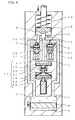
- Fig. 4 shows in cross section how the pressing mechanism of Fig. 1 causes the main piston to descend to its initial position.
- the piping for hydraulic oil 1 is placed within the body of the pressing mechanism, which prevents contamination of the surrounding area due to leakage of hydraulic oil 1.
- first piezoelectric element 16 is used, whose minute displacement is enlarged by displacement enlarging portion 17 for transmission to main piston 18.
- a spring with a large diameter is unnecessary, allowing downsizing of the pressing mechanism.
- a plurality of pressing mechanisms can be provided corresponding thereto, so that each piston 18 can be controlled individually using relevant first piezoelectric element 16. Accordingly, it becomes possible to push up respective main pistons 18 evenly, with high accuracy.
- supply control valve 22 and discharge control valve 25 have both been located close to main cylinder 6 in supply line 3 and discharge line 7, respectively. Instead, in Fig. 5, they both are located close to hydraulic oil source 2. Alternatively, supply control valve 22 and discharge control valve 25 may be located in any other places in supply line 3 and discharge line 7, respectively.
- a high degree of freedom is ensured for placement of supply control valve 22 and discharge control valve 25. Accordingly, it becomes possible to provide a pressing mechanism of a desired shape, e.g., of an elongated shape, or of a shape low in height and large in base area.
- first and second sub-cylinders 4, 13 have been provided for first piezoelectric element 16.
- just one stage of sub-cylinder may be provided, as long as one displacement of first piezoelectric element 16 can realize a displacement required for main piston 18.
- a sub-cylinder and a sub-piston of large area may be utilized to increase the displacement of main piston 18 corresponding to one displacement of first piezoelectric element 16.
- first piezoelectric element 16 may also be provided with more than two stages of sub-cylinders.
- the pressing portion 21 is provided separately from the portion where the hydraulic oil source (not shown) of the pressing mechanism is provided.
- a supplying pipe 28 as supply line 3 from the hydraulic oil source and a discharging pipe 29 as discharge line 7 to the hydraulic oil source are connected to pressing portion 21.
- supplying pipe 28 and discharging pipe 29 are each formed of a flexible pipe.
- the resin molding device of the present embodiment is provided with a lower mold 30 and an upper mold 31 facing each other.
- Lower mold 30 has a space of a cylindrical shape, in which a plunger 32 secured at an end of the axis integrated with main piston 18 is inserted.
- a portion above the plunger 32 forms a pot 33, in which a resin tablet (not shown) of a columnar shape made of thermosetting resin, for example, is placed.
- Upper mold 31 includes: a cull portion 34 for distributing the resin tablet molten by heat, or molten resin; a cavity 35 as a space into which the molten resin is introduced for hardening; and a gate portion 36 as an opening through which the molten resin is provided via cull portion 34 to cavity 35.
- pressing portion 21 is provided in a block 37 constituting a portion of the body of the resin molding device.
- the resin molding device shown in Fig. 6 is of the type in which a substrate with an electronic component in a chip form mounted therein is rested on a die-matching plane (indicated as P. L. in Fig.6), and molten resin is introduced into cavity 35 and hardened to resin-seal the substrate.
- hydraulic oil 1 being provided via supplying pipe 28 to main cylinder 6 causes main piston 18 to ascend, and thus, plunger 32 presses molten resin (not shown), which is introduced via cull portion 34, gate portion 36 into cavity 35.
- molten resin is hardened to cured resin
- lower mold 30 and upper mold 31 are separated, and the substrate integrated with the cured resin is taken out.
- the pressing mechanism of the present embodiment As explained above, according to the pressing mechanism of the present embodiment, as in the first embodiment, downsizing of the pressing mechanism is enabled, and if a plurality of main pistons 18 are provided, they can be pushed up evenly, with high accuracy.
- supplying pipe 28 and discharging pipe 29 are used for supply and discharge of hydraulic oil 1 between the hydraulic oil source and pressing portion 21, it becomes possible to place the hydraulic oil source and pressing portion 21 separately from each other. This increases the degree of freedom of design when designing a device using the pressing mechanism.
- the degree of freedom in designing the resin molding device is increased, and downsizing of the resin molding device is allowed.
- they can be controlled independently from each other with high accuracy. Accordingly, respective plungers 32 press the molten resin evenly, so that the molten resin can be introduced into corresponding cavities 35 with a uniform pressure. This prevents generation of voids or surface sinks in the molded articles.
- the pressing mechanism having the hydraulic oil source and pressing portion 21 provided separately from each other has been used.
- the pressing mechanism shown in Fig. 1 may be used alternatively, in which case contamination due to the hydraulic oil can further be prevented.
- first, second and third piezoelectric elements 16, 24 and 27 have been used to drive first sub-piston 10, supply control valve 22 and discharge control valve 25, respectively.
- electrical actuators like solenoids or air cylinders may be employed.
- any fluid working in a similar manner may be employed.
- bottom plate 9 has been held by gas 8 in Fig. 1, a compression spring may be employed instead of gas 8, or a combination of the compression spring and the gas may be employed. Further, compression spring 19 used in pressing portion 21 may be replaced with gas, or a combination of compression spring 19 and the gas may be employed.
Landscapes
- Engineering & Computer Science (AREA)
- Mechanical Engineering (AREA)
- Physics & Mathematics (AREA)
- Fluid Mechanics (AREA)
- General Engineering & Computer Science (AREA)
- Chemical & Material Sciences (AREA)
- Analytical Chemistry (AREA)
- Manufacturing & Machinery (AREA)
- Robotics (AREA)
- Casting Or Compression Moulding Of Plastics Or The Like (AREA)
- Injection Moulding Of Plastics Or The Like (AREA)
- Press Drives And Press Lines (AREA)
Abstract
Description
- The present invention relates to a pressing method, a pressing mechanism and a resin molding device that utilize pressure of working fluid.
- A pressing mechanism conventionally used in a resin sealing device, which introduces molten resin into a cavity to resin-seal an electronic component in a chip form in a substrate, or in other resin molding devices is of the type that has a base freely movable up and down. The base is provided with a cylindrical hole through which a piston is inserted via a spring, and the entire base is moved up and down by hydraulic pressure. In the case of the resin molding device, a plunger that is attached to an end of the piston is pushed up to press molten resin to make it enter the cavity, where the molten resin is hardened for resin molding.
- The conventional pressing mechanism, however, poses the following problems. First, the hydraulic pressing mechanism requires piping for hydraulic oil. The oil may leak out of the piping, contaminating the surrounding area. Such contamination becomes a serious problem especially in the assembly process of electronic components like semiconductor devices.
- In addition, to use a spring to transmit the movement of the base to the piston, the spring should have a large diameter to receive the pressure. This makes it difficult to downsize the pressing mechanism. Usually such a problem is fatal in the resin molding device employing a plurality of plungers, as it becomes difficult to downsize the device itself.
- Further, variation in spring characteristics is likely to cause variation in the way of pushing up the piston by the pressing mechanism. In the resin molding device employing a plurality of plungers, such variation is usually accompanied by variation in fluidity of the molten resin, making it difficult to push up the pistons in a uniform manner. This may create void or surface sink in a molded article, thereby degrading the quality thereof.
- An object of the present invention is to provide a pressing method, a pressing mechanism and a resin molding device employing the mechanism, which lessen variation in the way of pressing an object, prevent contamination due to working fluid, and permit downsizing of the pressing mechanism and the resin molding device.
- According to one aspect, the pressing method of the present invention for accomplishing the object above is a method for pressing an object with a main piston placed in a main cylinder by means of applying a prescribed pressure to the main piston with working fluid, wherein the working fluid is compressed to the prescribed pressure by supplying the working fluid to the main cylinder with driving power of a piezoelectric element.
- More specifically, a prescribed voltage is applied to the piezoelectric element repeatedly until the pressure of the working fluid reaches to the prescribed pressure.
- According to the present method, the piezoelectric elements each having an accurate displacement are displaced for repeatedly supplying the working fluid to the main cylinder and pressing it to displace the main piston in a stepped manner. Accordingly, the variation in the way of pressing the object by the main piston can further be alleviated.
- According to another aspect, the pressing method of the present invention relates to a method for pressing an object with a main piston, utilizing working fluid to which a prescribed pressure is applied through a piping system. The piping system includes a main cylinder, a supply line and a discharge line of the working fluid with respect to the main cylinder, a check valve preventing reverse flow of the working fluid from the main cylinder to the supply line, and a sub-cylinder provided in the supply line. The method includes: a first step of displacing a sub-piston provided within the sub-cylinder from its initial position to press the working fluid, and introducing the working fluid via the check valve into the main cylinder to displace the main piston provided within the main cylinder; and a second step of causing the sub-piston to return to the initial state to supply the working fluid to the sub cylinder. The first and second steps are repeated successively until the working fluid in the main cylinder attains a prescribed pressure level.
- More specifically, the first step is performed in the state where a discharge control valve provided in the discharge line and a supply control valve provided in the supply line are closed. The second step is performed in the state where the discharge control valve and the check valve are closed and the supply control valve is open.
- According to the pressing method, the main piston provided with the main cylinder is displaced in a stepped manner by repeating the step of supplying the working fluid to the sub-cylinder and the step of pressing the fluid. Accordingly, compared to the conventional pressing method in which the movement of the base is transmitted to the piston via the spring, the variation in the way of pressing the object by the main piston can be alleviated.
- In the pressing method of the present invention, a piezoelectric element as driving means is preferably attached to each of the supply control valve, the discharge control valve and the sub-piston. These piezoelectric elements serve to open and close the supply control valve and the discharge control valve, and to displace the sub-piston from its initial position.
- With such a step, the piezoelectric elements each having an accurate displacement are displaced for repeatedly supplying the working fluid to the sub-cylinder and pressing it to displace the main piston in a stepped manner. Accordingly, the variation in the way of pressing the object by the main piston can further be alleviated.
- In a preferred embodiment of the pressing method of the present invention, in the pressing method described above, a detector provided in the main cylinder detects the pressure of the working fluid, and when the detector detects the prescribed pressure level, the displacement of the sub-piston is terminated.
- With such a structure, it is possible to detect the pressure of the working fluid pressing the main piston and thus to detect the position of the main piston with accuracy. The main piston can be stopped when it reaches a prescribed position.
- The pressing mechanism of the present invention for accomplishing the object above is a pressing mechanism that presses an object using pressure of working fluid supplied from a working fluid source to a piping system with a prescribed pressure. The pressing mechanism includes: a main piston for pressing the object; a main cylinder having the main piston placed therein and supplied with the working fluid for displacement of the main piston; a check valve preventing reverse flow of the working fluid supplied to the main cylinder; a sub-cylinder linked to the main cylinder and having the working fluid reserved therein for supply to the main cylinder; a sub-piston placed within the sub-cylinder; a supply line for supplying the working fluid from the working fluid source to the sub-cylinder; a supply control valve provided in the supply line; a discharge line for discharging the working fluid from the main cylinder to the working fluid source; a discharge control valve provided in the discharge line; a first driving mechanism for driving the sub-piston; a second driving mechanism for driving the supply control valve; and a third driving mechanism for driving the discharge control valve.
- With this mechanism, the working fluid supplied to the sub-cylinder is pressed to push up the main piston, and the main piston presses the object.
- Preferably, in the pressing mechanism of the present invention, the first, second and third driving mechanisms each include a piezoelectric element, and the piezoelectric elements drive the sub-piston, the supply control valve and the discharge control valve, respectively.
- With such a mechanism, the piezoelectric elements each having an accurate displacement are used for repeatedly supplying the working fluid to the sub-cylinder and pressing it to displace the main piston in a stepped manner. Accordingly, the variation in the way of pressing the object by the main piston can be alleviated.
- In a preferred embodiment of the pressing mechanism of the present invention, of the first, second and third driving mechanisms, at least the first driving mechanism is provided with a displacement enlarging portion that enlarges the displacement of the sub-piston for transmission to the main piston.
- With such a mechanism, even a minute displacement of the first driving mechanism causes the working fluid to be pressed, and the main piston is displaced by the working fluid. Accordingly, it becomes possible to downsize the first driving mechanism and hence the entire pressing mechanism.
- In the pressing mechanism of the present invention, the piping system through which the working fluid flows may be built in the pressing mechanism. This can prevent the working fluid from leaking outside the pressing mechanism.
- The resin molding device of the present invention uses the pressing mechanism described above. The resin molding device includes: a reservoir in which molten resin is reserved; a plunger that is pressed by the main piston to press the molten resin; and a cavity into which the pressed molten resin is introduced. The molten resin introduced into the cavity is hardened for resin molding.
- With such a structure, the main piston is pushed up as the working fluid supplied to the sub-cylinder is pressed. The main piston then presses the plunger, and the plunger in turn presses the molten resin, so that the molten resin is introduced into the cavity.
- The pressing method, the pressing mechanism and the resin molding device of the present invention described above provide the following effects.
- First, as the step of supplying the working fluid to the sub-cylinder and the step of pressing it to displace the main piston in a stepped manner are repeated, variation in the way of pressing the object by the main piston can be lessened. As the piezoelectric element having an accurate displacement is displaced, the variation in the way of pressing the object by the main piston can further be alleviated.
- Further, by using the piezoelectric element, instead of a spring, as the driving means, downsizing of the pressing mechanism itself and hence the resin molding device itself is enabled.
- Still further, the piping system is built in the pressing mechanism, so that the leakage of the working fluid outside the pressing mechanism can be prevented.
- Accordingly, the present invention is practically very advantageous in that it provides the pressing method, the pressing mechanism and the resin molding device using the same that can reduce the variation in the way of pressing the object, prevent contamination due to the working fluid, and permit downsizing of the pressing mechanism and the resin molding device.
- The above pressing method and mechanism can effectively be applied to a method and a mechanism for driving plungers of a resin molding device, whereby the plungers can be controlled independently from each other with high accuracy. Accordingly, respective plungers press the molten resin evenly, so that the molten resin can be introduced into corresponding cavities with a uniform pressure. This prevents generation of voids or surface sinks in the molded articles.
- The foregoing and other objects, features, aspects and advantages of the present invention will become more apparent from the following detailed description of the present invention when taken in conjunction with the accompanying drawings.
-
- Fig. 1 is a cross sectional view showing a structure of the pressing mechanism according to a first embodiment of the present invention.
- Fig. 2 is a cross sectional view of the pressing mechanism of Fig. 1, illustrating how the main piston is pushed up.
- Fig. 3 is a cross sectional view of the pressing mechanism of Fig. 1, illustrating how a preparation is made for the main piston having been pushed up to be further pushed up.
- Fig. 4 is a cross sectional view of the pressing mechanism of Fig. 1, illustrating how the main piston is lowered to return to its initial position.
- Fig. 5 is a cross sectional view showing a structure of a variation of the pressing mechanism shown in Fig. 1.
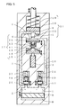
- Fig. 6 is a cross sectional view showing portions of the pressing mechanism and a resin molding device using the same according to a second embodiment of the present invention.
-
- A pressing mechanism and a pressing method according to the first embodiment will be described with reference to Figs. 1-4. Fig. 1 shows in cross section the structure of the pressing mechanism of the present embodiment.
- Referring to Fig. 1, a
supply line 3 links ahydraulic oil source 2 in whichhydraulic oil 1 as the working fluid is reserved to afirst sub-cylinder 4 and to amain cylinder 6 via acheck valve 5. Adischarge line 7 also linksmain cylinder 6 tohydraulic oil source 2.Gas 8 and abottom plate 9 apply a prescribed pressure tohydraulic oil 1 reserved inhydraulic oil source 2. Accordingly, thehydraulic oil 1 is kept at a prescribed pressure through the entire piping system fromhydraulic oil source 2, viasupply line 3,first sub-cylinder 4,main cylinder 6,discharge line 7, back tohydraulic oil source 2. -
Hydraulic oil 1 withinfirst sub-cylinder 4 is pressed by afirst sub-piston 10.First sub-piston 10 is pressed via apressure plate 11 by hydraulic oil reserved in asecond sub-cylinder 13. When the hydraulic oil stops pressing,pressure plate 11 is pushed down by acompression spring 12. The hydraulic oil reserved withinsecond sub-cylinder 13 is pressed by asecond sub-piston 15 via a leaf spring provided withinsecond sub-cylinder 13.Second sub-piston 15 is attached to an end of a first piezoelectric element 16 that drives thesub-piston 15. First sub-cylinder 4, first sub-piston 10,pressure plate 11,compression spring 12, second sub-cylinder 13, leaf spring 14, andsecond sub-piston 15 in all constitute adisplacement enlarging portion 17. - Check
valve 5 allows thehydraulic oil 1 pressed insupply line 3 to flow intomain cylinder 6, while it prevents reverse flow ofhydraulic oil 1 frommain cylinder 6 to supplyline 3. Amain piston 18 is provided withinmain cylinder 6, which ascends ashydraulic oil 1 flows viacheck valve 5 intomain cylinder 6, and descends ashydraulic oil 1 flows out ofmain cylinder 6 to dischargeline 7. Whenhydraulic oil 1 is discharged frommain cylinder 6 to dischargeline 7, acompression spring 19 ensures thatmain piston 18 is sufficiently pressed down. Apressure sensor 20 is provided on a wall surface ofmain cylinder 6, which detects a pressure of the working fluid inmain cylinder 6, i.e., the hydraulic pressure ofhydraulic oil 1. It generates an electrical signal corresponding to the hydraulic pressure, and outputs the signal to a control portion (not shown). Checkvalve 5,main cylinder 6,main piston 18,compression spring 19, andpressure sensor 20 in all constitute apressing portion 21 that is a main portion of the pressing mechanism. - A
supply control valve 22 is provided insupply line 3, which is driven via hydraulic oil by avalve piston 23 to open/close supply line 3.Valve piston 23 is attached to an end of a secondpiezoelectric element 24 that drives thepiston 23. - Similarly, a
discharge control valve 25 is provided indischarge line 7, which is driven via hydraulic oil by avalve piston 26, to open/close discharge line 7.Valve piston 26 is attached to an end of a thirdpiezoelectric element 27 by which it is driven. -
Supply control valve 22 anddischarge control valve 25 are each provided with a leaf spring (not shown), as insecond sub-cylinder 13, in a portion where the hydraulic oil is reserved. - Hereinafter, the pressing method using the pressing mechanism shown in Fig. 1 will be described with reference to Figs. 2-4. Fig. 2 shows in cross section how the pressing mechanism of Fig. 1 performs a pushing up operation of the main piston.
- Initially,
gas 8 andbottom plate 9 keephydraulic oil 1 at a prescribed pressure through the piping system, i.e., fromhydraulic oil source 2, viasupply line 3,first sub-cylinder 4,main cylinder 6,discharge line 7, and back tohydraulic oil source 2. - In this state, a prescribed voltage is applied to each of second and third
piezoelectric elements valve pistons piezoelectric elements supply control valve 22 closessupply line 3, and dischargecontrol valve 25 closes dischargeline 7. - Next, a prescribed voltage is applied to first piezoelectric element 16 to cause its end to protrude slightly, so that
second sub-piston 15 attached to the end of first piezoelectric element 16 is displaced upward in the drawing. Thus, the hydraulic oil withinsecond sub-cylinder 13presses pressure plate 11, which in turn pressesfirst sub-piston 10, which in turn presseshydraulic oil 1 withinfirst sub-cylinder 4. The pressedhydraulic oil 1 flows viacheck valve 5 intomain cylinder 6, so thatmain piston 18 is pushed up. - Here,
second sub-cylinder 13 is configured to have a cross section sufficiently larger than that of a portion ofpressure plate 11 receiving a pressure of the hydraulic oil fromsecond sub-cylinder 13. This enables the minute displacement of the end of first piezoelectric element 16 to be enlarged and transmitted tofirst sub-piston 10, and the enlarged displacement to be further transmitted viahydraulic oil 1 tomain piston 18. In other words,displacement enlarging portion 17 enlarges minute protrusion of the end of first piezoelectric element 16 for transmission tomain piston 18 to push it up. - Next, as shown in Fig. 3, a preparation is made to further push up
main piston 18. Fig. 3 shows in cross section how the pressing mechanism of Fig. 1, whose main piston has been pushed up, prepares for a succeeding pushing up operation of the main piston. - Here,
hydraulic oil 1 is introduced intofirst sub-cylinder 4, withmain piston 18 being maintained in its position. More specifically, the voltage having been applied to secondpiezoelectric element 24 is shut down to let its end return to the initial position. This lowersvalve piston 23, which in turn lowerssupply control valve 22 by means of the hydraulic oil, so thatsupply control valve 22 openssupply line 3. Further, the voltage having been applied to first piezoelectric element 16 is shut down to make its end return to the initial position. This lowerssecond sub-piston 15, which in turn lowersfirst sub-piston 10 by means of the hydraulic oil withinsecond sub-cylinder 13 and ofpressure plate 11. Through a series of these operations,displacement enlarging portion 17 works as a pump to lethydraulic oil 1 flow fromhydraulic oil source 2 tofirst sub-cylinder 4. During this process,check valve 5 is closed to prevent reverse flow ofhydraulic oil 1 withinmain cylinder 6 to supplyline 3, and dischargecontrol valve 25 is closed to prevent discharge of the oil to dischargeline 7. Accordingly,main piston 18 is maintained in place. - Next, the operation described in conjunction with Fig. 2 is repeated. Specifically, a prescribed voltage is applied to second
piezoelectric element 24 to let its end slightly protrude, so thatvalve piston 23 attached to the end is displaced upward. The displacement is enlarged by means of the hydraulic oil, and thus,supply control valve 22 closessupply line 3. - Further, a prescribed voltage is applied to first piezoelectric element 16, so that the end of first piezoelectric element 16 is slightly protruded or displaced upward.
Displacement enlarging portion 17 enlarges this minute displacement, and transmits the enlarged displacement tomain piston 18 to further push upmain piston 18. - Repeating the operations of pushing up
main piston 18 and of introducinghydraulic oil 1 intofirst sub-cylinder 4 causesmain piston 18 to ascend in a stepped manner.Pressure sensor 20 detects the hydraulic pressure withinmain cylinder 6, and outputs an electrical signal corresponding to the detected hydraulic pressure to a control portion (not shown). -
Main piston 18 is configured to ascend up to a preset position. When the hydraulic pressure withinmain cylinder 6 attains a prescribed pressure level corresponding to the position, i.e., when the control portion receives an electrical signal of a prescribed value, the control portion stops applying the voltage to first piezoelectric element 16. Thus, the end of first piezoelectric element 16 stops displacement and returns to its initial position, andsecond sub-piston 15 also stops displacement. Accordingly,main piston 18 is stopped at the preset position. - When
main piston 18 is no longer necessary to stay at the preset position,main piston 18 is lowered to return to its initial position, as shown in Fig. 4. Fig. 4 shows in cross section how the pressing mechanism of Fig. 1 causes the main piston to descend to its initial position. - Here, in the state where
supply line 3 is closed bysupply control valve 22, the voltage having been applied to thirdpiezoelectric element 27 is shut down to cause its end to return to the initial position. This lowersvalve piston 26, which in turn lowersdischarge control valve 25 by means of the hydraulic oil, so thatdischarge control valve 25 opens thedischarge line 7.Main piston 18 descends ascompression spring 19 pushes it downward. Withcheck valve 5 being closed, reverse flow ofhydraulic oil 1 withinmain cylinder 6 to supplyline 3 is prevented.Hydraulic oil 1 flows back tohydraulic oil source 2, so thatbottom plate 9 is pressed down. With these operations,main piston 18 returns to its initial position. - As explained above, according to the present embodiment, the piping for
hydraulic oil 1 is placed within the body of the pressing mechanism, which prevents contamination of the surrounding area due to leakage ofhydraulic oil 1. Further, first piezoelectric element 16 is used, whose minute displacement is enlarged bydisplacement enlarging portion 17 for transmission tomain piston 18. Thus, unlike the case where the ascent of the base is transmitted to the main piston by means of the spring, a spring with a large diameter is unnecessary, allowing downsizing of the pressing mechanism. To drive a plurality ofmain pistons 18, a plurality of pressing mechanisms can be provided corresponding thereto, so that eachpiston 18 can be controlled individually using relevant first piezoelectric element 16. Accordingly, it becomes possible to push up respectivemain pistons 18 evenly, with high accuracy. - A variation of the pressing mechanism of the present embodiment will now be described with reference to Fig. 5 showing the structure thereof.
- In the pressing mechanism shown in Fig. 1,
supply control valve 22 anddischarge control valve 25 have both been located close tomain cylinder 6 insupply line 3 and dischargeline 7, respectively. Instead, in Fig. 5, they both are located close tohydraulic oil source 2. Alternatively,supply control valve 22 anddischarge control valve 25 may be located in any other places insupply line 3 and dischargeline 7, respectively. - As explained above, according to the present embodiment, a high degree of freedom is ensured for placement of
supply control valve 22 anddischarge control valve 25. Accordingly, it becomes possible to provide a pressing mechanism of a desired shape, e.g., of an elongated shape, or of a shape low in height and large in base area. - In the present embodiment, two stages of sub-cylinders, first and
second sub-cylinders main piston 18. In this case, a sub-cylinder and a sub-piston of large area may be utilized to increase the displacement ofmain piston 18 corresponding to one displacement of first piezoelectric element 16. - To further increase the displacement of
main piston 18 corresponding to one displacement of first piezoelectric element 16, first piezoelectric element 16 may also be provided with more than two stages of sub-cylinders. - A pressing mechanism and a resin molding device using the same according to the second embodiment of the present invention will now be described with reference to Fig. 6 showing respective portions thereof.
- Referring to Fig. 6, the
pressing portion 21 is provided separately from the portion where the hydraulic oil source (not shown) of the pressing mechanism is provided. A supplyingpipe 28 assupply line 3 from the hydraulic oil source and a dischargingpipe 29 asdischarge line 7 to the hydraulic oil source are connected to pressingportion 21. Preferably, supplyingpipe 28 and dischargingpipe 29 are each formed of a flexible pipe. - As shown in Fig. 6, the resin molding device of the present embodiment is provided with a lower mold 30 and an upper mold 31 facing each other. Lower mold 30 has a space of a cylindrical shape, in which a plunger 32 secured at an end of the axis integrated with
main piston 18 is inserted. Of the space of the cylindrical shape, a portion above the plunger 32 forms a pot 33, in which a resin tablet (not shown) of a columnar shape made of thermosetting resin, for example, is placed. - Upper mold 31 includes: a cull portion 34 for distributing the resin tablet molten by heat, or molten resin; a cavity 35 as a space into which the molten resin is introduced for hardening; and a gate portion 36 as an opening through which the molten resin is provided via cull portion 34 to cavity 35.
- In the present embodiment, pressing
portion 21 is provided in ablock 37 constituting a portion of the body of the resin molding device. - The resin molding device shown in Fig. 6 is of the type in which a substrate with an electronic component in a chip form mounted therein is rested on a die-matching plane (indicated as P. L. in Fig.6), and molten resin is introduced into cavity 35 and hardened to resin-seal the substrate. Referring to Fig. 6,
hydraulic oil 1 being provided via supplyingpipe 28 tomain cylinder 6 causesmain piston 18 to ascend, and thus, plunger 32 presses molten resin (not shown), which is introduced via cull portion 34, gate portion 36 into cavity 35. After the molten resin is hardened to cured resin, lower mold 30 and upper mold 31 are separated, and the substrate integrated with the cured resin is taken out. - As explained above, according to the pressing mechanism of the present embodiment, as in the first embodiment, downsizing of the pressing mechanism is enabled, and if a plurality of
main pistons 18 are provided, they can be pushed up evenly, with high accuracy. In addition, since supplyingpipe 28 and dischargingpipe 29 are used for supply and discharge ofhydraulic oil 1 between the hydraulic oil source and pressingportion 21, it becomes possible to place the hydraulic oil source and pressingportion 21 separately from each other. This increases the degree of freedom of design when designing a device using the pressing mechanism. - Further, according to the resin molding device of the present embodiment, the degree of freedom in designing the resin molding device is increased, and downsizing of the resin molding device is allowed. In the case where there are a plurality of plungers 32, they can be controlled independently from each other with high accuracy. Accordingly, respective plungers 32 press the molten resin evenly, so that the molten resin can be introduced into corresponding cavities 35 with a uniform pressure. This prevents generation of voids or surface sinks in the molded articles.
- In the present embodiment, the pressing mechanism having the hydraulic oil source and pressing
portion 21 provided separately from each other has been used. However, the pressing mechanism shown in Fig. 1 may be used alternatively, in which case contamination due to the hydraulic oil can further be prevented. - In the respective embodiments described above, first, second and third
piezoelectric elements first sub-piston 10,supply control valve 22 anddischarge control valve 25, respectively. Alternatively, electrical actuators like solenoids or air cylinders may be employed. - Further, as the working fluid, instead of
hydraulic oil 1, any fluid working in a similar manner may be employed. - Although
bottom plate 9 has been held bygas 8 in Fig. 1, a compression spring may be employed instead ofgas 8, or a combination of the compression spring and the gas may be employed. Further,compression spring 19 used in pressingportion 21 may be replaced with gas, or a combination ofcompression spring 19 and the gas may be employed. - The resin molding device using the pressing mechanism has been described above. However, the pressing mechanism of the present invention is of course applicable to other devices.
- Although the present invention has been described and illustrated in detail, it is clearly understood that the same is by way of illustration and example only and is not to be taken by way of limitation, the spirit and scope of the present invention being limited only by the terms of the appended claims.
Claims (11)
- A method for pressing an object with a main piston (18) placed in a main cylinder (6) by means of applying a prescribed pressure to said main piston (18) with working fluid (1) wherein
said working fluid (1) is compressed to said prescribed pressure by supplying said working fluid (1) to said main cylinder (6) with driving power of a piezoelectric element (16). - The pressing method according to claim 1 wherein a prescribed voltage is applied to said piezoelectric element (16) repeatedly until the pressure of said working fluid reaches to said prescribed pressure.
- A method for pressing an object with a main piston (18) by means of working fluid (1) to which a prescribed pressure is applied through a piping system, the piping system including a main cylinder (6), a supply line (3) and a discharge line (7) of said working fluid (1) with respect to said main cylinder (6), a check valve (5) preventing reverse flow of said working fluid (1) from said main cylinder (6) to said supply line (3), and a sub-cylinder (4, 13) provided within said supply line (3), the pressing method comprising:a first step of displacing a sub-piston (10, 15) provided within said sub-cylinder (4, 13) from an initial position to press said working fluid (1) such that said working fluid (1) is introduced via said check valve (5) to said main cylinder (6) to displace said main piston (18) provided within said main cylinder (6); anda second step of causing said sub-piston (10, 15) to return to said initial position such that said working fluid (1) is supplied to said sub-cylinder (4, 13),said first step and said second step being repeated successively until pressure of said working fluid (1) in said main cylinder (6) reaches a prescribed pressure level.
- The pressing method according to claim 3 whereinsaid first step is performed in a state where a discharge control valve (25) disposed in said discharge line (7) and a supply control valve (22) disposed in said supply line (3) are closed, andsaid second step is performed in a state where said discharge control valve (25) and said check valve (5) are closed and said supply control valve (22) is open.
- The pressing method according to claim 4 whereinsaid supply control valve (22), said discharge control valve (25) and said sub-piston (10, 15) each have a piezoelectric element (16, 24, 27) attached thereto, andsaid piezoelectric elements (16, 24, 27) serve to open and close said supply control valve (22) and said discharge control valve (25), and to displace said sub-piston (10, 15) from the initial position, respectively.
- The pressing method according to claim 3 whereina detector (20) provided in said main cylinder (6) detects the pressure of said working fluid (1), andwhen said detector (20) detects said prescribed pressure level, the displacement of said sub-piston (10, 15) is terminated.
- A pressing mechanism for pressing an object by means of pressure of working fluid (1) that is supplied from a working fluid source (2) to a piping system with a prescribed pressure, comprising:a main piston (18) pressing said object;a main cylinder (6) having said main piston (18) placed therein, and supplied with said working fluid (1) for displacement of said main piston (18);a check valve (5) preventing reverse flow of said working fluid (1) supplied to said main cylinder (6);a sub-cylinder (4, 13) linked to said main cylinder (6) and having said working fluid (1) reserved therein for supply to said main cylinder (6);a sub-piston (10, 15) placed within said sub-cylinder (4, 13);a supply line (3) for supplying said working fluid (1) from said working fluid source (2) to said sub-cylinder (4, 13);a supply control valve (22) disposed in said supply line (3);a discharge line (7) for discharging said working fluid (1) from said main cylinder (6) to said working fluid source (2);a discharge control valve (25) disposed in said discharge line (7);a first driving mechanism driving said sub-piston (10, 15);a second driving mechanism driving said supply control valve (22); anda third driving mechanism driving said discharge control valve (25).
- The pressing mechanism according to claim 7 wherein said first, second and third driving mechanisms each have a piezoelectric element (16, 24, 27), and said piezoelectric elements (16, 24, 27) drive said sub-piston (10, 15), said supply control valve (22) and said discharge control valve (25), respectively.
- The pressing mechanism according to claim 7 wherein, of said first, second and third driving mechanisms, at least said first driving mechanism includes a displacement enlarging portion that enlarges displacement of said sub-piston (10, 15) for transmission to said main piston (18).
- The pressing mechanism according to claim 7 wherein said piping system through which said working fluid (1) flows is built in said pressing mechanism.
- A resin molding device using the pressing mechanism according to claim 7, comprising:a reservoir (34) in which molten resin is reserved;a plunger (32) that is pressed by said main piston (18) to press said molten resin; anda cavity (35) into which said pressed molten resin is introduced,the molten resin introduced into said cavity (35) being hardened for resin molding.
Applications Claiming Priority (2)
| Application Number | Priority Date | Filing Date | Title |
|---|---|---|---|
| JP2000260678 | 2000-08-30 | ||
| JP2000260678A JP3408233B2 (en) | 2000-08-30 | 2000-08-30 | Press method, press mechanism, and resin molding device |
Publications (3)
| Publication Number | Publication Date |
|---|---|
| EP1190829A2 true EP1190829A2 (en) | 2002-03-27 |
| EP1190829A3 EP1190829A3 (en) | 2002-12-11 |
| EP1190829B1 EP1190829B1 (en) | 2004-05-19 |
Family
ID=18748652
Family Applications (1)
| Application Number | Title | Priority Date | Filing Date |
|---|---|---|---|
| EP01306969A Expired - Fee Related EP1190829B1 (en) | 2000-08-30 | 2001-08-16 | Pressing method, pressing mechanism and resin molding device |
Country Status (6)
| Country | Link |
|---|---|
| US (1) | US6851355B2 (en) |
| EP (1) | EP1190829B1 (en) |
| JP (1) | JP3408233B2 (en) |
| KR (1) | KR100441188B1 (en) |
| DE (1) | DE60103341D1 (en) |
| TW (1) | TW504446B (en) |
Cited By (3)
| Publication number | Priority date | Publication date | Assignee | Title |
|---|---|---|---|---|
| WO2013160398A1 (en) * | 2012-04-25 | 2013-10-31 | Siemens Aktiengesellschaft | Actuator device and method for setting a position of a linearly movable element |
| WO2014001083A1 (en) * | 2012-06-29 | 2014-01-03 | Siemens Aktiengesellschaft | Actuator device and method for setting a position of a linearly movable element |
| CN105751560A (en) * | 2016-05-06 | 2016-07-13 | 福州大学 | Long-stroke wedge type energy-saving hydraulic machine and working method thereof |
Families Citing this family (7)
| Publication number | Priority date | Publication date | Assignee | Title |
|---|---|---|---|---|
| TW587008B (en) * | 2003-01-20 | 2004-05-11 | Asia Optical Co Inc | Pressure regulating device for injection molding mold unit |
| US20070157693A1 (en) * | 2006-01-10 | 2007-07-12 | Gkn Sinter Metals, Inc. | Forging/coining method |
| AT505724B1 (en) * | 2007-09-12 | 2010-06-15 | Trumpf Maschinen Austria Gmbh | DRIVE DEVICE FOR A BEND PRESS |
| CN101947839B (en) * | 2010-09-13 | 2013-05-08 | 凡嘉科技(无锡)有限公司 | Ejection mechanism for injection mold of thread cap |
| DE102012018606A1 (en) * | 2012-09-20 | 2014-03-20 | Fraunhofer-Gesellschaft zur Förderung der angewandten Forschung e.V. | Deep-drawing tool and method for deep-drawing a workpiece |
| WO2021160289A1 (en) * | 2020-02-14 | 2021-08-19 | Metismotion Gmbh | Actuator device and method for operating an actuator device of this type |
| KR102148632B1 (en) * | 2020-05-08 | 2020-08-26 | 박승일 | Hydraulic booster device using volume variable piston |
Citations (2)
| Publication number | Priority date | Publication date | Assignee | Title |
|---|---|---|---|---|
| JPH0878454A (en) * | 1994-09-06 | 1996-03-22 | Matsushita Electric Ind Co Ltd | Mold press equipment and mold press method |
| JP2000031178A (en) * | 1998-07-14 | 2000-01-28 | Nec Corp | Resin sealing device for semiconductor |
Family Cites Families (8)
| Publication number | Priority date | Publication date | Assignee | Title |
|---|---|---|---|---|
| US2382045A (en) * | 1942-06-19 | 1945-08-14 | Hydraulic Dev Corp Inc | Method of forging |
| JPS60177897A (en) * | 1984-02-24 | 1985-09-11 | 日本電信電話株式会社 | Piezoelectric type drill |
| JPH02111039A (en) * | 1988-10-20 | 1990-04-24 | Hitachi Ltd | Manufacture of semiconductor device and resin molding apparatus therefor |
| US5095725A (en) * | 1989-05-12 | 1992-03-17 | Fuji Electric Co., Ltd. | Press and actuator using piezoelectric element |
| JPH03279062A (en) * | 1990-03-28 | 1991-12-10 | Nissan Motor Co Ltd | Operating pressure control actuator for fluid pressure operating system |
| JPH05248405A (en) * | 1992-03-10 | 1993-09-24 | Kobe Steel Ltd | Pressurizer of working machine |
| JP2519665B2 (en) * | 1993-09-29 | 1996-07-31 | 日清紡績株式会社 | Double acting hydraulic cylinder |
| JP3208745B2 (en) * | 1997-12-16 | 2001-09-17 | ユーエイチティー株式会社 | Punch press |
-
2000
- 2000-08-30 JP JP2000260678A patent/JP3408233B2/en not_active Expired - Fee Related
-
2001
- 2001-08-13 US US09/929,694 patent/US6851355B2/en not_active Expired - Fee Related
- 2001-08-16 EP EP01306969A patent/EP1190829B1/en not_active Expired - Fee Related
- 2001-08-16 DE DE60103341T patent/DE60103341D1/en not_active Expired - Lifetime
- 2001-08-27 KR KR10-2001-0051682A patent/KR100441188B1/en not_active IP Right Cessation
- 2001-08-29 TW TW090121331A patent/TW504446B/en not_active IP Right Cessation
Patent Citations (2)
| Publication number | Priority date | Publication date | Assignee | Title |
|---|---|---|---|---|
| JPH0878454A (en) * | 1994-09-06 | 1996-03-22 | Matsushita Electric Ind Co Ltd | Mold press equipment and mold press method |
| JP2000031178A (en) * | 1998-07-14 | 2000-01-28 | Nec Corp | Resin sealing device for semiconductor |
Non-Patent Citations (2)
| Title |
|---|
| PATENT ABSTRACTS OF JAPAN vol. 1996, no. 07, 31 July 1996 (1996-07-31) & JP 08 078454 A (MATSUSHITA ELECTRIC IND CO LTD), 22 March 1996 (1996-03-22) * |
| PATENT ABSTRACTS OF JAPAN vol. 2000, no. 04, 31 August 2000 (2000-08-31) & JP 2000 031178 A (NEC CORP), 28 January 2000 (2000-01-28) * |
Cited By (5)
| Publication number | Priority date | Publication date | Assignee | Title |
|---|---|---|---|---|
| WO2013160398A1 (en) * | 2012-04-25 | 2013-10-31 | Siemens Aktiengesellschaft | Actuator device and method for setting a position of a linearly movable element |
| US10072677B2 (en) | 2012-04-25 | 2018-09-11 | Siemens Aktiengesellscahft | Actuator device and method for setting a position of a linearly movable element |
| WO2014001083A1 (en) * | 2012-06-29 | 2014-01-03 | Siemens Aktiengesellschaft | Actuator device and method for setting a position of a linearly movable element |
| CN105751560A (en) * | 2016-05-06 | 2016-07-13 | 福州大学 | Long-stroke wedge type energy-saving hydraulic machine and working method thereof |
| CN105751560B (en) * | 2016-05-06 | 2017-08-11 | 福州大学 | Long stroke wedge-type energy-saving hydraulic machine and its method of work |
Also Published As
| Publication number | Publication date |
|---|---|
| EP1190829B1 (en) | 2004-05-19 |
| TW504446B (en) | 2002-10-01 |
| JP3408233B2 (en) | 2003-05-19 |
| EP1190829A3 (en) | 2002-12-11 |
| JP2002067066A (en) | 2002-03-05 |
| US6851355B2 (en) | 2005-02-08 |
| DE60103341D1 (en) | 2004-06-24 |
| US20020023535A1 (en) | 2002-02-28 |
| KR20020018014A (en) | 2002-03-07 |
| KR100441188B1 (en) | 2004-07-22 |
Similar Documents
| Publication | Publication Date | Title |
|---|---|---|
| EP1190829B1 (en) | Pressing method, pressing mechanism and resin molding device | |
| JP5140517B2 (en) | Resin molding apparatus and resin molding method | |
| KR100196575B1 (en) | Resin sealing formation of electronic part and die device | |
| JP2016181548A (en) | Resin sealing device and resin sealing method | |
| US4812109A (en) | Apparatus for driving piston by fluid pressure | |
| JPS608123B2 (en) | Hollow article internal pressure forming apparatus and method | |
| KR20030043353A (en) | Cglinder and manufacturing method of multi position control ey linder which is used on hotrumner system mulfi position control cylinder | |
| JP4217572B2 (en) | Resin molding method and resin molding apparatus | |
| KR101333099B1 (en) | Press with plate-like frame parts, and method for operating such a plate press | |
| US5356283A (en) | Metal mold for sealing semiconductor devices with a resin | |
| US5520874A (en) | Compressible mold plunger | |
| JP3281586B2 (en) | Resin molding equipment | |
| JPH11197779A (en) | Hydraulic pressure generating device for full enclosed die forging | |
| JP2004337868A (en) | Forming method with hydraulic press | |
| JPH11179444A (en) | Device for punching printed circuit board | |
| TW576789B (en) | Device for applying closing force in injection molding machine in particular for producing shoe | |
| KR100553668B1 (en) | Resin sealing mold and resin sealing method | |
| JPS6295207A (en) | Transfer mold press | |
| KR102138935B1 (en) | Hydraulic device with manifold equipped with prefill valve | |
| JPH03151154A (en) | Vacuum die casting device | |
| KR20110097403A (en) | Apparatus and method for compression moding | |
| JPH08164535A (en) | Resin molding apparatus | |
| JP3195844B2 (en) | Transfer mold equipment | |
| KR100210703B1 (en) | Gas booster | |
| SU1498988A1 (en) | Power cylinder |
Legal Events
| Date | Code | Title | Description |
|---|---|---|---|
| PUAI | Public reference made under article 153(3) epc to a published international application that has entered the european phase |
Free format text: ORIGINAL CODE: 0009012 |
|
| AK | Designated contracting states |
Kind code of ref document: A2 Designated state(s): AT BE CH CY DE DK ES FI FR GB GR IE IT LI LU MC NL PT SE TR |
|
| AX | Request for extension of the european patent |
Free format text: AL;LT;LV;MK;RO;SI |
|
| RIN1 | Information on inventor provided before grant (corrected) |
Inventor name: TAKEHARA, MASATAKA, C/O TOWA CORPORATION Inventor name: HARADA, AKIYUKI, C/O TOWA CORPORATION |
|
| PUAL | Search report despatched |
Free format text: ORIGINAL CODE: 0009013 |
|
| AK | Designated contracting states |
Kind code of ref document: A3 Designated state(s): AT BE CH CY DE DK ES FI FR GB GR IE IT LI LU MC NL PT SE TR |
|
| AX | Request for extension of the european patent |
Free format text: AL;LT;LV;MK;RO;SI |
|
| RIC1 | Information provided on ipc code assigned before grant |
Free format text: 7B 29C 45/02 A, 7B 29C 43/36 B, 7F 15B 3/00 B, 7F 15B 7/08 B, 7F 15B 11/12 B |
|
| 17P | Request for examination filed |
Effective date: 20030509 |
|
| AKX | Designation fees paid |
Designated state(s): DE GB NL |
|
| GRAP | Despatch of communication of intention to grant a patent |
Free format text: ORIGINAL CODE: EPIDOSNIGR1 |
|
| GRAS | Grant fee paid |
Free format text: ORIGINAL CODE: EPIDOSNIGR3 |
|
| GRAA | (expected) grant |
Free format text: ORIGINAL CODE: 0009210 |
|
| AK | Designated contracting states |
Kind code of ref document: B1 Designated state(s): DE GB NL |
|
| REG | Reference to a national code |
Ref country code: GB Ref legal event code: FG4D |
|
| REG | Reference to a national code |
Ref country code: IE Ref legal event code: FG4D |
|
| REF | Corresponds to: |
Ref document number: 60103341 Country of ref document: DE Date of ref document: 20040624 Kind code of ref document: P |
|
| PG25 | Lapsed in a contracting state [announced via postgrant information from national office to epo] |
Ref country code: DE Free format text: LAPSE BECAUSE OF FAILURE TO SUBMIT A TRANSLATION OF THE DESCRIPTION OR TO PAY THE FEE WITHIN THE PRESCRIBED TIME-LIMIT Effective date: 20040820 |
|
| PLBE | No opposition filed within time limit |
Free format text: ORIGINAL CODE: 0009261 |
|
| STAA | Information on the status of an ep patent application or granted ep patent |
Free format text: STATUS: NO OPPOSITION FILED WITHIN TIME LIMIT |
|
| 26N | No opposition filed |
Effective date: 20050222 |
|
| REG | Reference to a national code |
Ref country code: IE Ref legal event code: MM4A |
|
| PG25 | Lapsed in a contracting state [announced via postgrant information from national office to epo] |
Ref country code: GB Free format text: LAPSE BECAUSE OF NON-PAYMENT OF DUE FEES Effective date: 20050816 |
|
| PG25 | Lapsed in a contracting state [announced via postgrant information from national office to epo] |
Ref country code: NL Free format text: LAPSE BECAUSE OF NON-PAYMENT OF DUE FEES Effective date: 20060301 |
|
| GBPC | Gb: european patent ceased through non-payment of renewal fee |
Effective date: 20050816 |
|
| NLV4 | Nl: lapsed or anulled due to non-payment of the annual fee |
Effective date: 20060301 |