EP1190552B1 - Load balancing apparatus and method - Google Patents
Load balancing apparatus and method Download PDFInfo
- Publication number
- EP1190552B1 EP1190552B1 EP00983842A EP00983842A EP1190552B1 EP 1190552 B1 EP1190552 B1 EP 1190552B1 EP 00983842 A EP00983842 A EP 00983842A EP 00983842 A EP00983842 A EP 00983842A EP 1190552 B1 EP1190552 B1 EP 1190552B1
- Authority
- EP
- European Patent Office
- Prior art keywords
- path
- usage
- total
- highest
- lowest
- Prior art date
- Legal status (The legal status is an assumption and is not a legal conclusion. Google has not performed a legal analysis and makes no representation as to the accuracy of the status listed.)
- Expired - Lifetime
Links
Images

Classifications
-
- H—ELECTRICITY
- H04—ELECTRIC COMMUNICATION TECHNIQUE
- H04L—TRANSMISSION OF DIGITAL INFORMATION, e.g. TELEGRAPHIC COMMUNICATION
- H04L47/00—Traffic control in data switching networks
- H04L47/10—Flow control; Congestion control
-
- H—ELECTRICITY
- H04—ELECTRIC COMMUNICATION TECHNIQUE
- H04L—TRANSMISSION OF DIGITAL INFORMATION, e.g. TELEGRAPHIC COMMUNICATION
- H04L43/00—Arrangements for monitoring or testing data switching networks
-
- H—ELECTRICITY
- H04—ELECTRIC COMMUNICATION TECHNIQUE
- H04L—TRANSMISSION OF DIGITAL INFORMATION, e.g. TELEGRAPHIC COMMUNICATION
- H04L47/00—Traffic control in data switching networks
- H04L47/10—Flow control; Congestion control
- H04L47/12—Avoiding congestion; Recovering from congestion
- H04L47/125—Avoiding congestion; Recovering from congestion by balancing the load, e.g. traffic engineering
-
- H—ELECTRICITY
- H04—ELECTRIC COMMUNICATION TECHNIQUE
- H04L—TRANSMISSION OF DIGITAL INFORMATION, e.g. TELEGRAPHIC COMMUNICATION
- H04L43/00—Arrangements for monitoring or testing data switching networks
- H04L43/02—Capturing of monitoring data
- H04L43/022—Capturing of monitoring data by sampling
-
- H—ELECTRICITY
- H04—ELECTRIC COMMUNICATION TECHNIQUE
- H04L—TRANSMISSION OF DIGITAL INFORMATION, e.g. TELEGRAPHIC COMMUNICATION
- H04L43/00—Arrangements for monitoring or testing data switching networks
- H04L43/08—Monitoring or testing based on specific metrics, e.g. QoS, energy consumption or environmental parameters
- H04L43/0876—Network utilisation, e.g. volume of load or congestion level
-
- H—ELECTRICITY
- H04—ELECTRIC COMMUNICATION TECHNIQUE
- H04L—TRANSMISSION OF DIGITAL INFORMATION, e.g. TELEGRAPHIC COMMUNICATION
- H04L43/00—Arrangements for monitoring or testing data switching networks
- H04L43/16—Threshold monitoring
Definitions
- the present invention is directed to a path balancing apparatus and method.
- the present invention is directed to an apparatus and method for workload balancing along multiple communication paths to a plurality of devices.
- US 5,799,173 discloses a method for dynamically controlling the number of servers in a transaction system comprising at least one service unit for processing service requests.
- Each service unit comprises a queue for receiving and queuing the incoming service requests and a plurality of service for executing the service requests.
- the method comprises a first step of monitoring the current number of service requests and the current number of servers allocated to each one of the service units, a second step of determining an optimised number of servers for each one of the service units dependent on the current number of service requests and the current number of servers, and a third step of allocating the optimised number of servers for each one of the service units.
- EP-A-0,892,531 discloses a message despatch system for a multicomputer server having a number of server computers connected via respective server network links.
- the message despatch system which is connectable to an external telecommunications network, includes a message despatcher configured to receive external client requests for the multicomputer server from the external communications network and to despatch the client request to selected server computers via the server network links.
- the message despatcher is configured to determine a server to which an external client request is to be despatched in response to parameters representative of message traffic volume on the server network links. Load balancing is performed based on parameters representative of the server network link loading, rather than, or possibly in addition to measurements on processor loading. Suitable network loading parameters can be derived by monitoring packets passing from and/or to the individual server computers. The monitoring can be performed in the despatcher, or in a switch or a separate traffic monitor between the despatcher and the server network links, for example.
- the present invention provides an apparatus and method for workload balancing along multiple communication paths to a plurality of devices.
- the apparatus includes a controller that accumulates path usage information and a path balancing device that makes use of the accumulated path usage information to perform a path balancing operation if a difference in a total path usage of a path having a highest path usage and a total path usage of a path having a lowest path usage is greater than a threshold usage amount.
- the path balancing method of the present invention involves the path balancing device calculating the total expected connect time for all I/O messages issued to each of a plurality of peripheral devices during a predefined sampling period. These totals are then added for each communication path for the sampling period to obtain path totals. The path totals are then compared to see if a difference between the highest used path and the lowest used path is greater than a threshold amount. If the difference is higher than the threshold amount, the peripheral device having a total expected connect time that is closest to a target value is moved from the highest used path to the lowest used path.
- the lowest used path will receive more I/O messages while the highest used path will receive less I/O messages.
- the difference between the highest use path and the lowest used path should fall below the threshold amount and the system will be well balanced.
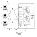
- Figure 1 is an exemplary diagram of a multiple path system 100 in which the present invention may be implemented.
- the system 100 includes open system devices 110, 120 and 130, routers 180 and 190, and a shared virtual array 140 of virtual peripheral devices 160 representing at least one physical peripheral device 165.
- the shared virtual array 140 further includes a plurality of interface devices 150 for providing a communication gateway between the open system devices 110, 120 and 130 and the plurality of virtual peripheral devices 160.
- the open system devices 110, 120 and 130 may be, for example, devices that provide interoperability between hardware and software that is defined by the industry at large and not only by a select few vendors.
- the open system devices 110, 120 and 130 may be UNIX-based devices, personal computers, database management systems (DBMSs) that run on many different platforms, or any other tools that may be used across multiple platforms.
- DBMSs database management systems
- the shared virtual array 140 is an array of virtual peripheral devices 160 that may be accessed by the open system devices 110, 120 and 130.
- the shared virtual array 140 is "virtual" in that each physical peripheral device 165 in the shared virtual array 140 may be represented as a plurality of virtual devices.
- the physical peripheral device 165 is a storage device having a storage capacity, through compaction and compression methods, the amount of used storage space may be decreased and thus, the storage capacity effectively increased without actually increasing the size of the storage device. In this way, a single physical storage device may be represented as a plurality of virtual storage devices to the open system devices 110-130.
- the physical peripheral device 165 may be any type of device connected to the open system devices 110, 120 and 130.
- the physical peripheral device 165 may be a disk drive, a hard drive, a CD-ROM drive, a magnetic tape drive, a monitor, a printer, a database device, and the like. Any type of device that may be utilized by a plurality of open system devices 110-130 may be used as a physical peripheral device 165 without departing from the spirit and scope of the present invention.
- the virtual peripheral devices 160 which represent the physical peripheral device 165 may be grouped into domains, such as Domain A and Domain B in Figure 1 .
- Each open system device 110-130 may be provided access to virtual peripheral devices 160 in certain domains and not in other domains.
- the communication links 170 and 175 from each open system device 110-130 may be capable of communicating with each virtual peripheral device 160 in the shared virtual array 140, the actual virtual peripheral devices 160 that may be communicated with may be restricted by the domain structure.
- the shared virtual array 140 further includes a plurality of interface devices 150 through which the open system devices 110-130 communicate with the virtual peripheral devices 160.
- the interface devices 150 may be any type of device that provides a communication gateway through which communication between the open system devices 110-130 and the virtual peripheral devices 160 may be accomplished.
- the interface devices 150 may be an ESCON ( E nterprise S ystems CON nection) interface, a Small Computer System Interface (SCSI) interface, a fibre channel interface, a modem, a network interface, a network hub, or the like.
- the interface devices 150 are capable of providing a communication gateway connection to each of the virtual peripheral devices 160. In other words, each interface device 150 "sees" each of the virtual peripheral devices 160. However, as noted above, access to certain peripheral device domains may be restricted based on the particular open system device 110-130 attempting to access the virtual peripheral devices 160.
- the open system devices 110-130 communicate with the interface devices 150, and ultimately with the virtual peripheral devices 160, via communication links 170 and 175.
- the communication links 170 and 175 may be any type of communication links that are capable of transmitting information to and from the open system devices 110-130 and the shared virtual array 140.
- the communication links may be fiber optic links, packet switched communication links, ESCON fibers, SCSI cable links, wireless communication links, and the like.
- each communication link 170 and 175 as a separate physical communication connection between the open system devices 110-130 and the interface devices 150
- the invention is not limited to such an embodiment. Rather, the communication connections may be embodied, for example, as separate communication channels in the same physical communication connection. Likewise, the same physical communication connection may make use of different wavelengths or frequencies to provide separate communication links.
- each open system device 110 may have a plurality of communication paths by which to reach a particular virtual peripheral device 160 in its assigned domain.
- the virtual peripheral devices 160 have a plurality of communication paths by which to communicate with the open system devices 110-130.
- the present invention aims at balancing the workload to the virtual peripheral devices 160 across the plurality of communication paths. This concept is also referred to as path balancing.
- the path balancing method of the present invention involves the open system devices 110-130 calculating the total expected connect time for all I/O messages issued to each of the peripheral devices during a predefined sampling period.
- the total expected connect time for all I/O messages is a function of the type of I/O messages issued. For example, the expected connect time for a "read" I/O message may be a first value while the expected connect time for a "write” I/O message may be a second value.
- path totals are then added for each communication path for the sampling period to obtain path totals.
- the path totals are then compared to see if a difference between the highest used path and the lowest used path is greater than a threshold amount. If the difference is higher than the threshold amount, the peripheral device having a total expected connect time that is closest to a target value is moved from the highest used path to the lowest used path.
- the lowest used path will receive more I/O messages while the highest used path will receive less I/O messages.
- the difference between the highest use path and the lowest used path should fall below the threshold amount and the system will be well balanced.
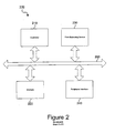
- Figure 2 is an exemplary block diagram of an open system device 110. Although Figure 2 represents open system device 110, it should be appreciated by those of ordinary skill in the art that the other open system devices 120-130 may have similar structures and operate in a similar manner to open system device 110.
- the open system device 110 includes a controller 210, a memory 220, a path balancing device 230, and a peripheral interface 240. These elements 210-240 are in communication with one another via the control/signal bus 250.
- a bus architecture is shown in Figure 2 , other architectures as will be apparent to those of ordinary skill in the art, are intended to be within the spirit and scope of the present invention.
- the controller 210 controls the operation of the open system device 110 based on, for example, control programs stored in memory 220.
- the controller 210 communicates with the virtual peripheral devices 160 over the communication links 170 via the peripheral interface 240.
- the controller 210 samples the workload of each communication path over a sampling period and stores the workload information in memory 220, for example. This may be accomplished by storing the number and expected connection time for each I/O message for each virtual peripheral device 160 as the I/O message is generated by the open system device 110.
- the controller 210 instructs the path balancing device 230 to perform a path balancing operation on the communication paths of the peripheral interface 240.
- the path balancing device 230 retrieves the sampled workload data from the memory 230 and determines a total usage for each communication path. The total usage for a communication path over the sampling period is determined to be the total of the expected connection times for each virtual peripheral device 160 capable of being accessed over the communication path.
- the path balancing device 230 compares the totals to determine the highest usage communication path and the lowest usage communication path. The total usage for the highest and lowest usage communication paths are then subtracted to obtain a difference between the total usage of the highest and lowest usage communication paths.
- the path balancing device 230 determines, based on the total usage for each virtual peripheral device 160 capable of being accessed by the highest usage communication path, which virtual peripheral device 160 to move from the highest usage communication path to the lowest usage communication path. This determination is based on which of the virtual peripheral devices 160 has a usage amount closest to a target value.
- the virtual peripheral device 160 that is moved is the virtual peripheral device 160 whose total usage over the sampling period is closest to one half the difference between the total usage for the highest usage communication path and the total usage for the lowest usage communication path. This process is then repeated until the highest and lowest usage communication paths no longer have a difference in usage greater than the threshold usage amount.
- the preferred embodiment uses a target value that is one half the difference between the total usage for the highest usage communication path and the total usage for the lowest usage communication path
- the invention is not limited to such a target value. Rather, the target value is tuneable and may be set to any value that is appropriate for the desired functioning of the invention. Thus, the target value may be set to one third of the difference, three quarters of the difference, or any other fraction thereof. Furthermore, the target value may be independent of the difference or may be arbitrarily set.
- Movement of a virtual peripheral device 160 from one communication path to another may be performed, for example, by changing the address information for the virtual peripheral device 160 in the open system device 110 or in the routers 180 and 190. Alternatively, movement may be performed physically by altering the communication links such that the virtual peripheral device 160 or the physical peripheral device 165 is connected to a different communication link.
- the movement of virtual peripheral devices 160 may be constrained by a movement limit set for each time interval.
- the movement limit may be set to 1 ⁇ 2 the number of communication paths.
- This movement limit is intended to prevent large numbers of virtual peripheral devices 160 from being moved and thus, causing a pendulum effect in the workload balance being shifted from one set of virtual peripheral devices 160 to another.
- the general path balancing method performed by the path balancing device 230 described above may be represented by the following algorithm:
- the present invention provides an apparatus and method by which the overall throughput of a multiple communication path system may be increased by balancing the workload to provide roughly equal utilization of all of the system resources. Furthermore, the invention provides a high availability environment as long as there are at least two communication paths functioning. Should a communication path fail, the path balancing method will relocate the virtual peripheral devices 160 on that communication path to one or more other communication paths, thereby reducing system downtime.
- Tables 1 and 2 illustrate the benefits achieved by the present invention.
- Table 1 represents an unbalanced system during one time interval.
- Table 1 - Unbalanced System Device and Path Usage Path 1 Path 2 Path 3 Path 4 Device Usage Device Usage Device Usage 1 20 2 15 3 40 4 20 8 7 7 15 6 20 5 20 9 7 10 7 11 15 12 10 15 7 14 7 13 10 Total 34 44 82 60
- the highest usage path is path 3 and the lowest usage path is path 1. It is assumed that the threshold difference between path usage is set to 15. The difference between the usage for path 3 and the usage for path 1 is 48 and is thus, greater than the threshold difference of 15.
- the target value is equal to the difference divided by 2 and thus is 24.
- the virtual peripheral device associated with path 3 that has a usage that is closest to the target value is virtual peripheral device # 6.
- virtual peripheral device # 6 is moved from path 3 to path 1.
- path 1 's usage is now 54 and path 3 's usage is now 62.
- path balancing method is repeated and path 3 is more than 15 points higher than path 2.
- /2 9). Accordingly, virtual peripheral device # 14 is moved from path 3 to path 2.
- the usage for path 2 is now 51 and the usage for path 3 is now 55.
- Table 2 shows the same system after the path balancing method is applied. As can be seen from Table 2, the system is now balanced such that no path has a usage that is greater than 15 points higher than any other path. Table 2 - Same system as Table 1 after path balancing Path 1 Path 2 Path 3 Path 4 Device Usage Device Usage Device Usage Device Usage 1 20 2 15 3 40 4 20 8 7 7 15 11 15 5 20 9 7 10 7 12 10 6 20 15 7 13 10 14 7 Total 54 51 55 60
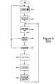
- FIG 3 is a flowchart outlining an exemplary operation of the open system device 110 according to the present invention.
- the process starts with the controller 210 accumulating path usage information and storing the path usage information in memory 220 (step 310 ).
- the controller 110 instructs the path balancing device 230 to perform a path balancing operation starting with determining the total usage for each path (step 320 ).
- the path balancing device 230 identifies the highest and lowest used paths based on the total usage for each path (step 330 ).
- the path balancing device 230 calculates a usage difference between the highest and lowest used paths and determines if the difference is greater than a threshold amount (step 340 ).
- step 340 :NO If the difference is not greater than the threshold amount (step 340 :NO), the path balancing device 230 determines that the system is well balanced and does not perform path balancing (returns to step 310 ). If the difference is greater than the threshold amount (step 340 :YES), the path balancing device 230 determines if the number of moved virtual peripheral devices 160 for the time interval is greater than or equal to a move limit (step 350 ).
- step 350 :YES If the number of moved virtual peripheral devices 160 for the time interval is greater than the move limit (step 350 :YES), the path balancing device 230 does not move any further virtual peripheral devices 160 (returns to step 310 ). If the number of moved virtual peripheral devices 160 for the time interval is not greater than the move limit (step 350:NO), the path balancing device 230 calculates a target usage (step 360 ).
- the path balancing device 230 determines the best virtual peripheral device 160 to be moved (step 370 ).
- the best virtual peripheral device 160 to be moved is the peripheral device whose usage is closest to one half the usage difference.
- Other selection criteria for the best virtual peripheral device to be moved may be used without departing from the spirit and scope of the present invention.
- the path balancing device 230 moves the device from the highest usage path to the lowest usage path and increments the number of moved virtual peripheral devices (step 380 ).
- the path balancing device 230 then continues the process by identifying the new highest and lowest used paths (step 330 ). This process is repeated until the difference between the usage of the highest used path and the lowest used path falls below the threshold amount (step 340 :NO).
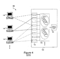
- the above embodiments of the present invention are described with reference to a system 100 in which the I/O messages are routed by routers 180 and 190 to the interface devices 150.
- the invention is not limited to such an arrangement.
- the routers 180 and 190 are not essential to the functioning of the invention.
- the system may make use of direct communication connections between the open system devices 110- 130 and the interface devices 150.
- Each open system device 110-130 may have multiple communication connections to different interface devices 150 thereby defining a plurality of communication paths by which the open system devices 110-130 may communicate with the virtual peripheral devices 160 in their assigned domains.
- the path balancing method described above is equally applicable to such an embodiment of the system 100.
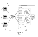
- the path balancing device 230 may be a separate device in communication with the open system devices 110-130 and the virtual peripheral devices 160.
- the path balancing device 230 may be coupled to the routers 180 and 190.
- the path balancing device 230 may be a centralized device through which the communication paths pass.
- Other arrangements and architectures may be used without departing from the scope of the present invention.
- the method of this invention is preferably implemented on a programmed processor.
- the path balancing device 230 can also be implemented on a general purpose or special purpose computer, a programmed microprocessor or microcontroller and peripheral integrated circuit elements, an Application Specific Integrated Circuit (ASIC) or other integrated circuit, a hardware electronic or logic circuit such as a discrete element circuit, a programmable logic device such as a PLD, PLA, FPGA or PAL, or the like.
- ASIC Application Specific Integrated Circuit
- any device capable of implementing the flowchart shown in Figure 3 can be used to implement the path balancing device 230 functions of this invention.
Abstract
Description
- The present invention is directed to a path balancing apparatus and method. In particular, the present invention is directed to an apparatus and method for workload balancing along multiple communication paths to a plurality of devices.
- Systems are known in which multiple peripheral devices may be accessed by processing devices via multiple communication paths. Multiple processing devices may access the peripheral devices over the same communication path.
Thus, some of these communication paths may be more utilized than others leading to an imbalance in the workloads for the communication paths.
This situation may lead to a loss in throughput of the overall system. - As a solution to this problem, the known systems require the peripheral devices to be manually configured or new peripheral devices to be added to the system to compensate for the imbalance in workload. However, this solution has proven unsatisfactory in that the workloads of the communication paths do not become adequately balanced.
- Thus, a need is present for new technology to provide an apparatus and method for balancing workloads across a plurality of communication paths.
-
US 5,799,173 (A ) discloses a method for dynamically controlling the number of servers in a transaction system comprising at least one service unit for processing service requests. Each service unit comprises a queue for receiving and queuing the incoming service requests and a plurality of service for executing the service requests. The method comprises a first step of monitoring the current number of service requests and the current number of servers allocated to each one of the service units, a second step of determining an optimised number of servers for each one of the service units dependent on the current number of service requests and the current number of servers, and a third step of allocating the optimised number of servers for each one of the service units. -
EP-A-0,892,531 discloses a message despatch system for a multicomputer server having a number of server computers connected via respective server network links. The message despatch system, which is connectable to an external telecommunications network, includes a message despatcher configured to receive external client requests for the multicomputer server from the external communications network and to despatch the client request to selected server computers via the server network links. The message despatcher is configured to determine a server to which an external client request is to be despatched in response to parameters representative of message traffic volume on the server network links. Load balancing is performed based on parameters representative of the server network link loading, rather than, or possibly in addition to measurements on processor loading. Suitable network loading parameters can be derived by monitoring packets passing from and/or to the individual server computers. The monitoring can be performed in the despatcher, or in a switch or a separate traffic monitor between the despatcher and the server network links, for example. - The present invention provides an apparatus and method for workload balancing along multiple communication paths to a plurality of devices. The apparatus includes a controller that accumulates path usage information and a path balancing device that makes use of the accumulated path usage information to perform a path balancing operation if a difference in a total path usage of a path having a highest path usage and a total path usage of a path having a lowest path usage is greater than a threshold usage amount.
- The path balancing method of the present invention involves the path balancing device calculating the total expected connect time for all I/O messages issued to each of a plurality of peripheral devices during a predefined sampling period. These totals are then added for each communication path for the sampling period to obtain path totals. The path totals are then compared to see if a difference between the highest used path and the lowest used path is greater than a threshold amount. If the difference is higher than the threshold amount, the peripheral device having a total expected connect time that is closest to a target value is moved from the highest used path to the lowest used path.
- In this way, the lowest used path will receive more I/O messages while the highest used path will receive less I/O messages. Over a number of iterations, the difference between the highest use path and the lowest used path should fall below the threshold amount and the system will be well balanced.
- The novel features believed characteristic of the invention are set forth in the appended claims. The invention itself, however, as well as a preferred mode of use, further objectives and advantages thereof, will best be understood by reference to the following detailed description of an illustrative embodiment when read in conjunction with the accompanying drawings, wherein:
-
Figure 1 is an exemplary diagram of a multiple path system in which the present invention may be implemented; -
Figure 2 is an exemplary block diagram of a system according to the present invention; -
Figure 3 is a flowchart outlining an exemplary operation of the open system ofFigure 2 ; -
Figure 4 is an exemplary block diagram of an alternative embodiment of the system ofFigure 1 in which the communication links are direct communication links between the open system devices and the interface devices; -
Figure 5 is an exemplary block diagram of an alternative embodiment of the system ofFigure 1 in which the path balancing device is coupled to the routers; -
Figure 6 is an exemplary block diagram of an alternative embodiment of the system ofFigure 1 in which the path balancing device is a centralized device; and - Appendix I is an example of pseudocode for performing a method of path balancing according to the present invention.
-
Figure 1 is an exemplary diagram of amultiple path system 100 in which the present invention may be implemented. As shown inFigure 1 , thesystem 100 includesopen system devices routers virtual array 140 of virtualperipheral devices 160 representing at least one physicalperipheral device 165. The sharedvirtual array 140 further includes a plurality ofinterface devices 150 for providing a communication gateway between theopen system devices peripheral devices 160. - The
open system devices open system devices - The shared
virtual array 140 is an array of virtualperipheral devices 160 that may be accessed by theopen system devices virtual array 140 is "virtual" in that each physicalperipheral device 165 in the sharedvirtual array 140 may be represented as a plurality of virtual devices. For example, if the physicalperipheral device 165 is a storage device having a storage capacity, through compaction and compression methods, the amount of used storage space may be decreased and thus, the storage capacity effectively increased without actually increasing the size of the storage device. In this way, a single physical storage device may be represented as a plurality of virtual storage devices to the open system devices 110-130. - The physical
peripheral device 165 may be any type of device connected to theopen system devices peripheral device 165 may be a disk drive, a hard drive, a CD-ROM drive, a magnetic tape drive, a monitor, a printer, a database device, and the like. Any type of device that may be utilized by a plurality of open system devices 110-130 may be used as a physicalperipheral device 165 without departing from the spirit and scope of the present invention. - The virtual
peripheral devices 160 which represent the physicalperipheral device 165 may be grouped into domains, such as Domain A and Domain B inFigure 1 . Each open system device 110-130 may be provided access to virtualperipheral devices 160 in certain domains and not in other domains.
Thus, although thecommunication links peripheral device 160 in the sharedvirtual array 140, the actual virtualperipheral devices 160 that may be communicated with may be restricted by the domain structure. - The shared
virtual array 140 further includes a plurality ofinterface devices 150 through which the open system devices 110-130 communicate with the virtualperipheral devices 160. Theinterface devices 150 may be any type of device that provides a communication gateway through which communication between the open system devices 110-130 and the virtualperipheral devices 160 may be accomplished. For example, theinterface devices 150 may be an ESCON (Enterprise Systems CONnection) interface, a Small Computer System Interface (SCSI) interface, a fibre channel interface, a modem, a network interface, a network hub, or the like. - The
interface devices 150 are capable of providing a communication gateway connection to each of the virtualperipheral devices 160. In other words, eachinterface device 150 "sees" each of the virtualperipheral devices 160. However, as noted above, access to certain peripheral device domains may be restricted based on the particular open system device 110-130 attempting to access the virtualperipheral devices 160. - The open system devices 110-130 communicate with the
interface devices 150, and ultimately with the virtualperipheral devices 160, viacommunication links communication links virtual array 140. For example, the communication links may be fiber optic links, packet switched communication links, ESCON fibers, SCSI cable links, wireless communication links, and the like. - Although
Figure 1 represents eachcommunication link interface devices 150, the invention is not limited to such an embodiment. Rather, the communication connections may be embodied, for example, as separate communication channels in the same physical communication connection. Likewise, the same physical communication connection may make use of different wavelengths or frequencies to provide separate communication links. - The
routers communication links 170 and route them to the virtualperipheral devices 160 via the communication links 175. Thus, as shown inFigure 1 , eachopen system device 110 may have a plurality of communication paths by which to reach a particular virtualperipheral device 160 in its assigned domain. Likewise, the virtualperipheral devices 160 have a plurality of communication paths by which to communicate with the open system devices 110-130. The present invention aims at balancing the workload to the virtualperipheral devices 160 across the plurality of communication paths. This concept is also referred to as path balancing. - The path balancing method of the present invention involves the open system devices 110-130 calculating the total expected connect time for all I/O messages issued to each of the peripheral devices during a predefined sampling period. The total expected connect time for all I/O messages is a function of the type of I/O messages issued. For example, the expected connect time for a "read" I/O message may be a first value while the expected connect time for a "write" I/O message may be a second value.
- These totals are then added for each communication path for the sampling period to obtain path totals. The path totals are then compared to see if a difference between the highest used path and the lowest used path is greater than a threshold amount. If the difference is higher than the threshold amount, the peripheral device having a total expected connect time that is closest to a target value is moved from the highest used path to the lowest used path.
- In this way, the lowest used path will receive more I/O messages while the highest used path will receive less I/O messages. Over a number of iterations, the difference between the highest use path and the lowest used path should fall below the threshold amount and the system will be well balanced.
-
Figure 2 is an exemplary block diagram of anopen system device 110. AlthoughFigure 2 representsopen system device 110, it should be appreciated by those of ordinary skill in the art that the other open system devices 120-130 may have similar structures and operate in a similar manner toopen system device 110. - As shown in
Figure 2 , theopen system device 110 includes acontroller 210, amemory 220, apath balancing device 230, and aperipheral interface 240. These elements 210-240 are in communication with one another via the control/signal bus 250. Although a bus architecture is shown inFigure 2 , other architectures as will be apparent to those of ordinary skill in the art, are intended to be within the spirit and scope of the present invention. - The
controller 210 controls the operation of theopen system device 110 based on, for example, control programs stored inmemory 220. Thecontroller 210 communicates with the virtualperipheral devices 160 over thecommunication links 170 via theperipheral interface 240. - The
controller 210 samples the workload of each communication path over a sampling period and stores the workload information inmemory 220, for example. This may be accomplished by storing the number and expected connection time for each I/O message for each virtualperipheral device 160 as the I/O message is generated by theopen system device 110. - The
controller 210, at predetermined time intervals, such as at the end of each sampling period, instructs thepath balancing device 230 to perform a path balancing operation on the communication paths of theperipheral interface 240. In response, thepath balancing device 230 retrieves the sampled workload data from thememory 230 and determines a total usage for each communication path. The total usage for a communication path over the sampling period is determined to be the total of the expected connection times for each virtualperipheral device 160 capable of being accessed over the communication path. - Once the total usage for each communication path is determined, the
path balancing device 230 compares the totals to determine the highest usage communication path and the lowest usage communication path. The total usage for the highest and lowest usage communication paths are then subtracted to obtain a difference between the total usage of the highest and lowest usage communication paths. - If this difference is greater than a threshold difference, the system is determined to be unbalanced. If the system is unbalanced, the
path balancing device 230 determines, based on the total usage for each virtualperipheral device 160 capable of being accessed by the highest usage communication path, which virtualperipheral device 160 to move from the highest usage communication path to the lowest usage communication path. This determination is based on which of the virtualperipheral devices 160 has a usage amount closest to a target value. - In a preferred embodiment, the virtual
peripheral device 160 that is moved is the virtualperipheral device 160 whose total usage over the sampling period is closest to one half the difference between the total usage for the highest usage communication path and the total usage for the lowest usage communication path. This process is then repeated until the highest and lowest usage communication paths no longer have a difference in usage greater than the threshold usage amount. - Although the preferred embodiment uses a target value that is one half the difference between the total usage for the highest usage communication path and the total usage for the lowest usage communication path, the invention is not limited to such a target value. Rather, the target value is tuneable and may be set to any value that is appropriate for the desired functioning of the invention. Thus, the target value may be set to one third of the difference, three quarters of the difference, or any other fraction thereof. Furthermore, the target value may be independent of the difference or may be arbitrarily set.
- Movement of a virtual
peripheral device 160 from one communication path to another may be performed, for example, by changing the address information for the virtualperipheral device 160 in theopen system device 110 or in therouters peripheral device 160 or the physicalperipheral device 165 is connected to a different communication link. - In addition to the above, the movement of virtual
peripheral devices 160 may be constrained by a movement limit set for each time interval. For example, the movement limit may be set to ½ the number of communication paths. Thus, if the number of virtualperipheral devices 160 that have already been moved in the current time interval is greater than ½ the number of communication paths, further movement of virtualperipheral devices 160 is prohibited. This movement limit is intended to prevent large numbers of virtualperipheral devices 160 from being moved and thus, causing a pendulum effect in the workload balance being shifted from one set of virtualperipheral devices 160 to another. - Additionally, the following constraints on virtual
peripheral device 160 movement may be used to provide better path balancing results: - 1) if there is only one virtual
peripheral device 160 per communication path in a time interval, movement of virtualperipheral devices 160 is prohibited; - 2) there must be more than one virtual
peripheral device 160 on a communication path before one of the virtualperipheral devices 160 may be moved from the communication path; - 3) each virtual
peripheral device 160 may be moved only once during each time interval; and - 4) if two virtual
peripheral devices 160 are determined to be the best virtualperipheral device 160 to be moved, the first virtualperipheral device 160 in the set ofperipheral devices 160 is chosen. - The general path balancing method performed by the
path balancing device 230 described above may be represented by the following algorithm:
   Num_moved = 0
   Identify hi path and lo path
   While ((hi-lo)>T1*hi&&num_moved<move_limit){
    Target=(hi-lo)/2
    If(hi path contains device(s) with
     |value-target|<T2*target) {
      find device on hi path with smallest
     |value-target| and move this device from hi path
    to lo path
     ++num_moved
     identify new hi and lo paths
     }
   else{
     exit algorithm
   }
  )
where hi is the largest path load, lo is the lowest path load, hi path is the communication path with the largest path load, lo path is the communication path with the lowest path load, T1 and T2 are algorithm parameters representing thresholds such that 0<T1, T2<=1, target is the target load for each communication path, num_moved is the number of virtual | Path 1 | | Path 3 | Path 4 | ||||
| Device | Usage | Device | Usage | Device | Usage | Device | Usage |
| 1 | 20 | 2 | 15 | 3 | 40 | 4 | 20 |
| 8 | 7 | 7 | 15 | 6 | 20 | 5 | 20 |
| 9 | 7 | 10 | 7 | 11 | 15 | 12 | 10 |
| 15 | 7 | 14 | 7 | 13 | 10 | ||
| Total | 34 | 44 | 82 | 60 | |||
| Path 1 | | Path 3 | Path 4 | ||||
| Device | Usage | Device | Usage | Device | Usage | Device | Usage |
| 1 | 20 | 2 | 15 | 3 | 40 | 4 | 20 |
| 8 | 7 | 7 | 15 | 11 | 15 | 5 | 20 |
| 9 | 7 | 10 | 7 | 12 | 10 | ||
| 6 | 20 | 15 | 7 | 13 | 10 | ||
| 14 | 7 | ||||||
| Total | 54 | 51 | 55 | 60 | |||
Claims (26)
- A method of balancing path usage over a plurality of paths from at least one first device to a plurality of second devices, comprising:determining (320) a total path usage for each of the plurality of paths; andperforming (330, 340, 350, 360, 370, 380) path balancing if a difference in a total path usage of a path having a highest path usage and a total path usage of a path having a lowest path usage is greater than a threshold usage amount.
- The method of claim 1, wherein the path balancing includes:identifying (330) a highest path from the plurality of paths, the highest path having a highest total path usage;identifying (330) a lowest path from the plurality of paths, the lowest path having a lowest total path usage; andcalculating (340) a difference between the total path usage of the highest path and the lowest path to form a calculated difference.
- The method of claim 2, wherein each of the plurality of second devices is associated with at least one of the plurality of paths and wherein the path balancing includes moving a second device from the highest path to the lowest path based on the calculated difference.
- The method of claim 3, wherein the second device remains unmoved if a number of moved second devices is equal to or greater than a move limit.
- The method of claim 3, wherein the second device that is moved is the second device from the plurality of second devices that has a usage amount closest to a target amount.
- The method of claim 5, wherein the target amount is a fraction of the difference of the total path usage of the highest path and the lowest path.
- The method of claim 1, wherein the total usage for each path is a function of the total usage for each second device associated with each path.
- The method of claim 7, wherein the total usage for each second device is a function of a total number of input/output messages directed to each second device multiplied by the expected connect time for the input/output messages.
- The method of claim 8, wherein the expected connect time for the input/output messages is based on the type of input/output message being sent.
- The method of claim 1, wherein determining a total path usage for each of the plurality of paths includes sampling a number of input/output messages issued over each of the paths during a sampling period.
- The method of claim 3, wherein moving the second device from the highest path to the lowest path based on the calculated difference includes changing address information for the second device.
- The method of claim 4, wherein the move limit is set to one half the number of paths.
- The method of claim 4, wherein if only one second device is associated with the highest path, movement of the one second device to the lowest path is prohibited.
- The method of claim 1, wherein the plurality of paths comprise a plurality of communication paths from at least one open system device to a plurality of peripheral devices, the method comprising:calculating a total path usage for each of the plurality of communication paths; identifying a highest communication path from the plurality of communication paths, the highest communication path having a highest total path usage;identifying a lowest communication path from the plurality of communication paths, the lowest communication path having a lowest total path usage;calculating a difference between the total path usage of the highest communication path and the lowest communication path to form a calculated difference; andmoving a peripheral device associated with the highest communication path from the highest communication path to the lowest communication path based on the calculated difference.
- The method of claim 14, wherein the peripheral device remains unmoved if a number of moved peripheral devices is equal to or greater than a move limit.
- The method of claim 14, wherein the peripheral device that is moved is the peripheral device from the plurality of peripheral devices that has a usage amount closest to a target amount.
- The method of claim 16, wherein the target amount is a fraction of the difference of the total path usage of the highest communication path and the lowest communication path.
- The method of claim 14, wherein the total usage for each communication path is a function of the total usage for each peripheral device associated with each communication path, respectively.
- The method of claim 18, wherein the total usage for each peripheral device is a function of a total number of input/output messages directed to each peripheral device, respectively, multiplied by the expected connect time for the input/output messages.
- The method of claim 19, wherein the expected connect time for the input/output messages is based on the type of input/output message being sent.
- The method of claim 14, wherein calculating a total path usage for each of the plurality of communication paths includes sampling a number of input/output messages issued over the plurality of communication paths during a sampling period.
- The method of claim 14, wherein moving the peripheral device from the highest path to the lowest path based on the calculated difference includes changing address information for the peripheral device.
- The method of claim 15, wherein the move limit is set to one half the plurality of communication paths.
- The method of claim 15, wherein if there is only one peripheral device associated with the highest path, movement of the one peripheral device to the lowest path is prohibited.
- A computer program product in a computer readable medium for balancing path usage over a plurality of paths from at least one first device to a plurality of second devices, the computer program product comprising: instructions for carrying out the method of any one of the preceding claims.
- A path balancing apparatus that balances the path usage over a plurality of paths from at least one first device to a plurality of second devices, the apparatus comprising means for carrying out the method of any one of claims 1 to 24.
Applications Claiming Priority (3)
| Application Number | Priority Date | Filing Date | Title |
|---|---|---|---|
| US09/453,657 US6728770B1 (en) | 1999-12-03 | 1999-12-03 | Method and apparatus for workload balancing along multiple communication paths to a plurality of devices |
| US453657 | 1999-12-03 | ||
| PCT/US2000/032657 WO2001041362A2 (en) | 1999-12-03 | 2000-11-30 | Load balance apparatus and method |
Publications (2)
| Publication Number | Publication Date |
|---|---|
| EP1190552A2 EP1190552A2 (en) | 2002-03-27 |
| EP1190552B1 true EP1190552B1 (en) | 2010-03-17 |
Family
ID=23801517
Family Applications (1)
| Application Number | Title | Priority Date | Filing Date |
|---|---|---|---|
| EP00983842A Expired - Lifetime EP1190552B1 (en) | 1999-12-03 | 2000-11-30 | Load balancing apparatus and method |
Country Status (5)
| Country | Link |
|---|---|
| US (2) | US6728770B1 (en) |
| EP (1) | EP1190552B1 (en) |
| AU (1) | AU2055101A (en) |
| DE (1) | DE60044025D1 (en) |
| WO (1) | WO2001041362A2 (en) |
Families Citing this family (26)
| Publication number | Priority date | Publication date | Assignee | Title |
|---|---|---|---|---|
| US6665702B1 (en) | 1998-07-15 | 2003-12-16 | Radware Ltd. | Load balancing |
| EP1104205A1 (en) * | 1999-11-25 | 2001-05-30 | Siemens Aktiengesellschaft | Method for optimized processing of connexions outside a switching exchange |
| CA2415433A1 (en) * | 2000-07-28 | 2002-02-07 | Immunex Corporation | A human disintegrin protein |
| US6985577B2 (en) * | 2000-07-28 | 2006-01-10 | Siemens Aktiengesellschaft | Device for optimizing the circuit switching capacity of a switching center |
| US6907461B2 (en) * | 2001-03-29 | 2005-06-14 | International Business Machines Corporation | Interactive data processor controlled display interface for tracking allocated messages in a dynamic workload balancing communication system |
| US20030079018A1 (en) * | 2001-09-28 | 2003-04-24 | Lolayekar Santosh C. | Load balancing in a storage network |
| US8578215B2 (en) * | 2001-11-19 | 2013-11-05 | Hewlett-Packard Development Company, L.P. | Method and system for gathering data using automatic appliance failover |
| US7239608B2 (en) * | 2002-04-26 | 2007-07-03 | Samsung Electronics Co., Ltd. | Router using measurement-based adaptable load traffic balancing system and method of operation |
| US7146389B2 (en) * | 2002-08-30 | 2006-12-05 | Hitachi, Ltd. | Method for rebalancing free disk space among network storages virtualized into a single file system view |
| US7657508B2 (en) * | 2006-12-29 | 2010-02-02 | Teradata Us, Inc. | Automated block size management for database objects |
| US7337235B2 (en) * | 2004-10-28 | 2008-02-26 | International Business Machines Corporation | Dynamic path partitioning to multipath storage devices |
| JP4757038B2 (en) * | 2006-01-25 | 2011-08-24 | 株式会社日立製作所 | Storage system and storage control device |
| US9110597B2 (en) * | 2007-12-10 | 2015-08-18 | Hewlett-Packard Development Company, L.P. | Data processing method and system |
| US7962650B2 (en) * | 2008-04-10 | 2011-06-14 | International Business Machines Corporation | Dynamic component placement in an event-driven component-oriented network data processing system |
| JP4551947B2 (en) * | 2008-05-23 | 2010-09-29 | 株式会社日立製作所 | Device that manages the electronic devices that make up the storage system |
| US8230077B2 (en) * | 2008-06-06 | 2012-07-24 | International Business Machines Corporation | Hypervisor-based facility for communicating between a hardware management console and a logical partition |
| US20100036981A1 (en) * | 2008-08-08 | 2010-02-11 | Raghavendra Ganesh | Finding Hot Call Paths |
| US8346995B2 (en) | 2008-09-30 | 2013-01-01 | Microsoft Corporation | Balancing usage of hardware devices among clients |
| US8245229B2 (en) * | 2008-09-30 | 2012-08-14 | Microsoft Corporation | Temporal batching of I/O jobs |
| US9377958B2 (en) * | 2014-08-12 | 2016-06-28 | Facebook, Inc. | Allocation of read/write channels for storage devices |
| US10067800B2 (en) * | 2014-11-06 | 2018-09-04 | Vmware, Inc. | Peripheral device sharing across virtual machines running on different host computing systems |
| US10355945B2 (en) | 2016-09-21 | 2019-07-16 | International Business Machines Corporation | Service level management of a workload defined environment |
| US10572310B2 (en) | 2016-09-21 | 2020-02-25 | International Business Machines Corporation | Deploying and utilizing a software library and corresponding field programmable device binary |
| US10599479B2 (en) | 2016-09-21 | 2020-03-24 | International Business Machines Corporation | Resource sharing management of a field programmable device |
| US10417012B2 (en) | 2016-09-21 | 2019-09-17 | International Business Machines Corporation | Reprogramming a field programmable device on-demand |
| CN111585908B (en) * | 2019-02-15 | 2022-03-04 | 贵州白山云科技股份有限公司 | Intelligent hotspot breaking method and device, storage medium and computer equipment |
Family Cites Families (12)
| Publication number | Priority date | Publication date | Assignee | Title |
|---|---|---|---|---|
| US4403286A (en) * | 1981-03-06 | 1983-09-06 | International Business Machines Corporation | Balancing data-processing work loads |
| US5239649A (en) * | 1989-10-30 | 1993-08-24 | International Business Machines Corporation | Channel path load balancing, through selection of storage volumes to be processed, for long running applications |
| US5313584A (en) * | 1991-11-25 | 1994-05-17 | Unisys Corporation | Multiple I/O processor system |
| EP0694837A1 (en) | 1994-07-25 | 1996-01-31 | International Business Machines Corporation | Dynamic workload balancing |
| US6263368B1 (en) | 1997-06-19 | 2001-07-17 | Sun Microsystems, Inc. | Network load balancing for multi-computer server by counting message packets to/from multi-computer server |
| JP3369445B2 (en) * | 1997-09-22 | 2003-01-20 | 富士通株式会社 | Network service server load adjusting device, method and recording medium |
| US6167427A (en) * | 1997-11-28 | 2000-12-26 | Lucent Technologies Inc. | Replication service system and method for directing the replication of information servers based on selected plurality of servers load |
| US6006259A (en) * | 1998-11-20 | 1999-12-21 | Network Alchemy, Inc. | Method and apparatus for an internet protocol (IP) network clustering system |
| US6434637B1 (en) * | 1998-12-31 | 2002-08-13 | Emc Corporation | Method and apparatus for balancing workloads among paths in a multi-path computer system based on the state of previous I/O operations |
| US6393458B1 (en) * | 1999-01-28 | 2002-05-21 | Genrad, Inc. | Method and apparatus for load balancing in a distributed object architecture |
| US6317808B1 (en) * | 1999-03-26 | 2001-11-13 | Adc Telecommunications, Inc. | Data storage system and method of routing or assigning disk write requests among a set of disks using weighted available disk space values |
| US6629148B1 (en) * | 1999-08-27 | 2003-09-30 | Platform Computing Corporation | Device and method for balancing loads between different paths in a computer system |
-
1999
- 1999-12-03 US US09/453,657 patent/US6728770B1/en not_active Expired - Lifetime
-
2000
- 2000-11-30 EP EP00983842A patent/EP1190552B1/en not_active Expired - Lifetime
- 2000-11-30 DE DE60044025T patent/DE60044025D1/de not_active Expired - Lifetime
- 2000-11-30 AU AU20551/01A patent/AU2055101A/en not_active Abandoned
- 2000-11-30 WO PCT/US2000/032657 patent/WO2001041362A2/en active Application Filing
-
2004
- 2004-03-12 US US10/799,172 patent/US7080146B2/en not_active Expired - Lifetime
Also Published As
| Publication number | Publication date |
|---|---|
| EP1190552A2 (en) | 2002-03-27 |
| DE60044025D1 (en) | 2010-04-29 |
| US20040174888A1 (en) | 2004-09-09 |
| US6728770B1 (en) | 2004-04-27 |
| US7080146B2 (en) | 2006-07-18 |
| AU2055101A (en) | 2001-06-12 |
| WO2001041362A3 (en) | 2002-01-10 |
| WO2001041362A2 (en) | 2001-06-07 |
Similar Documents
| Publication | Publication Date | Title |
|---|---|---|
| EP1190552B1 (en) | Load balancing apparatus and method | |
| JP4686606B2 (en) | Method, computer program, and system for dynamic distribution of input / output workload among removable media devices attached via multiple host bus adapters | |
| US11546644B2 (en) | Bandwidth control method and apparatus, and device | |
| US7225242B2 (en) | System and method for matching storage device queue depth to server command queue depth | |
| EP1116082B1 (en) | Dynamic load balancer for multiple network servers | |
| US6795860B1 (en) | System and method for selecting a service with dynamically changing information | |
| US6421723B1 (en) | Method and system for establishing a storage area network configuration | |
| CN101118521B (en) | System and method for spanning multiple logical sectorization to distributing virtual input-output operation | |
| US7188198B2 (en) | Method for implementing dynamic virtual lane buffer reconfiguration | |
| US6748414B1 (en) | Method and apparatus for the load balancing of non-identical servers in a network environment | |
| US20110238839A1 (en) | Network intrusion detection apparatus | |
| US20110134761A1 (en) | Dynamically provisioning virtual machines | |
| US11909663B1 (en) | Methods and apparatus for efficient use of link aggregation groups | |
| US8578053B2 (en) | NAS load balancing system | |
| US20060168156A1 (en) | Hierarchical system configuration method and integrated scheduling method to provide multimedia streaming service on two-level double cluster system | |
| US10908940B1 (en) | Dynamically managed virtual server system | |
| JPH06350648A (en) | Method and equipment for storing data packet | |
| US8356098B2 (en) | Dynamic management of workloads in clusters | |
| US6480471B1 (en) | Hardware sampler for statistical monitoring of network traffic | |
| US20110314171A1 (en) | System and method for providing pooling or dynamic allocation of connection context data | |
| US20050195834A1 (en) | Load distribution system | |
| US20070053349A1 (en) | Network interface accessing multiple sized memory segments | |
| US5459713A (en) | Self-configuring data communication system and method | |
| US7443870B2 (en) | Method for prioritizing grouped data reduction | |
| JP4309321B2 (en) | Network system operation management method and storage apparatus |
Legal Events
| Date | Code | Title | Description |
|---|---|---|---|
| PUAI | Public reference made under article 153(3) epc to a published international application that has entered the european phase |
Free format text: ORIGINAL CODE: 0009012 |
|
| AK | Designated contracting states |
Kind code of ref document: A2 Designated state(s): AT BE CH CY DE DK ES FI FR GB GR IE IT LI LU MC NL PT SE TR |
|
| AX | Request for extension of the european patent |
Free format text: AL;LT;LV;MK;RO;SI |
|
| 17P | Request for examination filed |
Effective date: 20020419 |
|
| RBV | Designated contracting states (corrected) |
Designated state(s): DE FR |
|
| 17Q | First examination report despatched |
Effective date: 20080502 |
|
| GRAP | Despatch of communication of intention to grant a patent |
Free format text: ORIGINAL CODE: EPIDOSNIGR1 |
|
| GRAS | Grant fee paid |
Free format text: ORIGINAL CODE: EPIDOSNIGR3 |
|
| GRAA | (expected) grant |
Free format text: ORIGINAL CODE: 0009210 |
|
| AK | Designated contracting states |
Kind code of ref document: B1 Designated state(s): DE FR |
|
| REF | Corresponds to: |
Ref document number: 60044025 Country of ref document: DE Date of ref document: 20100429 Kind code of ref document: P |
|
| PLBE | No opposition filed within time limit |
Free format text: ORIGINAL CODE: 0009261 |
|
| STAA | Information on the status of an ep patent application or granted ep patent |
Free format text: STATUS: NO OPPOSITION FILED WITHIN TIME LIMIT |
|
| 26N | No opposition filed |
Effective date: 20101220 |
|
| REG | Reference to a national code |
Ref country code: FR Ref legal event code: PLFP Year of fee payment: 16 |
|
| REG | Reference to a national code |
Ref country code: FR Ref legal event code: PLFP Year of fee payment: 17 |
|
| REG | Reference to a national code |
Ref country code: FR Ref legal event code: PLFP Year of fee payment: 18 |
|
| REG | Reference to a national code |
Ref country code: FR Ref legal event code: PLFP Year of fee payment: 19 |
|
| PGFP | Annual fee paid to national office [announced via postgrant information from national office to epo] |
Ref country code: DE Payment date: 20191119 Year of fee payment: 20 |
|
| PGFP | Annual fee paid to national office [announced via postgrant information from national office to epo] |
Ref country code: FR Payment date: 20191014 Year of fee payment: 20 |
|
| REG | Reference to a national code |
Ref country code: DE Ref legal event code: R071 Ref document number: 60044025 Country of ref document: DE |