EP1190182B1 - Gas spring - Google Patents
Gas spring Download PDFInfo
- Publication number
- EP1190182B1 EP1190182B1 EP00942265A EP00942265A EP1190182B1 EP 1190182 B1 EP1190182 B1 EP 1190182B1 EP 00942265 A EP00942265 A EP 00942265A EP 00942265 A EP00942265 A EP 00942265A EP 1190182 B1 EP1190182 B1 EP 1190182B1
- Authority
- EP
- European Patent Office
- Prior art keywords
- piston rod
- piston
- rod
- cylinder
- gas spring
- Prior art date
- Legal status (The legal status is an assumption and is not a legal conclusion. Google has not performed a legal analysis and makes no representation as to the accuracy of the status listed.)
- Expired - Lifetime
Links
- 230000006835 compression Effects 0.000 claims description 10
- 238000007906 compression Methods 0.000 claims description 10
- 230000015572 biosynthetic process Effects 0.000 description 2
- 238000005755 formation reaction Methods 0.000 description 2
- 230000000694 effects Effects 0.000 description 1
- 238000009434 installation Methods 0.000 description 1
Images




Classifications
-
- F—MECHANICAL ENGINEERING; LIGHTING; HEATING; WEAPONS; BLASTING
- F16—ENGINEERING ELEMENTS AND UNITS; GENERAL MEASURES FOR PRODUCING AND MAINTAINING EFFECTIVE FUNCTIONING OF MACHINES OR INSTALLATIONS; THERMAL INSULATION IN GENERAL
- F16F—SPRINGS; SHOCK-ABSORBERS; MEANS FOR DAMPING VIBRATION
- F16F9/00—Springs, vibration-dampers, shock-absorbers, or similarly-constructed movement-dampers using a fluid or the equivalent as damping medium
- F16F9/32—Details
- F16F9/54—Arrangements for attachment
-
- F—MECHANICAL ENGINEERING; LIGHTING; HEATING; WEAPONS; BLASTING
- F16—ENGINEERING ELEMENTS AND UNITS; GENERAL MEASURES FOR PRODUCING AND MAINTAINING EFFECTIVE FUNCTIONING OF MACHINES OR INSTALLATIONS; THERMAL INSULATION IN GENERAL
- F16F—SPRINGS; SHOCK-ABSORBERS; MEANS FOR DAMPING VIBRATION
- F16F9/00—Springs, vibration-dampers, shock-absorbers, or similarly-constructed movement-dampers using a fluid or the equivalent as damping medium
- F16F9/32—Details
- F16F9/3207—Constructional features
Definitions
- This invention relates to a gas spring of the type used, for example, to assist the opening of a vehicle door.
- EP-A1-0508778 discloses cylinder means, a piston rod slidably mounted in the cylinder means and carrying a piston.
- the piston divides the cylinder means into a first working chamber containing the piston rod and a second working chamber.
- a gas spring comprising, cylinder means, a piston rod slidably mounted within the cylinder means and carrying a piston, the piston dividing the cylinder means into a first working chamber containing the piston rod and a second working chamber, characterised in that rod limit means are mechanically coupled to and movable with the piston rod and cylinder limit means, are located within the first chamber and are mechanically coupled to the cylinder means, the limit of maximum extension of the piston rod out of the cylinder means being provided by contact between the rod limit means and the cylinder limit means, the rod limit means and/or the cylinder limit means being axially movable to adjust the limit of maximum extension of the piston rod.
- a conventional gas spring 2 has cylinder means 4, and a piston 6 carried on a piston rod 8.
- the piston 6 is slidable within the cylinder means 4.
- the piston rod carries a fixing cage 10 which is fixable to a vehicle body or vehicle door.
- the cylinder means 4 carries a fixing cage 12 for mounting to the other of a vehicle body or door.
- the cylinder means 4 contains gas under pressure which acts on both faces of the piston 6. However, since the piston rod 8 is located in one of the chambers defined within the cylinder means by the piston 6, the pressurised gas acts on a greater surface area of the piston 6 in the upper chamber 14 than in the lower chamber 16. Thus the piston rod is forced out of the cylinder means 4 by gas pressure.
- the gas spring 2 may be used to assist in lifting a vehicle door such as a hatchback.
- the gas pressure, the mounting positions of the cages 10 and 12 and the diameter of the piston rod 8 will be chosen such that the gas spring exerts sufficient force to lift the hatchback without user assistance until the piston is in the position shown in the Figure in which it abuts an end stop 18. In this position, the vehicle door, such as a hatchback, is fully open.
- the fully-open position of the hatchback must be selected to provide sufficient height for tall drivers to reach into the boot beneath the hatchback. However, for shorter drivers, this may mean that it is difficult to reach up to the hatchback to close it again.
- FIG. 2 shows the prior art adjustment mechanism of Figure 2 .
- This mechanism comprises a modified fixing cage 10' which includes a threaded neck portion 20 into which the piston rod 8 passes.
- the piston rod 8 has a correspondingly threaded portion and by rotating the piston rod 8 relative to the fixing cage 10', it is possible to vary the extended length LE between the two cages 10 and 12 when the gas spring is at its maximum extension position. This correspondingly varies the height of the hatchback when it is fully open.
- Figure 2B shows the position of minimum extension
- Figure 2C shows the position of maximum extension.
- the gas spring of Figure 1 is shown in more detail.
- the cylinder means 4 is sealingly closed by an end piece 20 at one end and at the other end of the cylinder means 4, the piston rod 8 passes through a rod guide 22, a seal 24 and an end stop 26.
- the piston 6 is held on the piston rod 8 by a washer 28 and includes a generally annular groove which holds a movable piston ring 30.
- the piston 6 carries out a guiding function and also a speed regulation function.
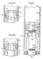
- Figures 4A and 4B show the piston 6 and cylinder means 4 in more detail.
- a gas spring in accordance with the invention is shown with the piston rod fully extended and providing a maximum extension length LE1.
- the gas spring has cylinder means 104 having a grooved portion 138 and containing a piston 106.
- the piston 106 is held on a piston rod 108 by a washer 128.
- the piston has an annular groove which holds a piston ring 130.
- the piston rod 108 passes through a rod guide 122, a lower seal 124 and an end stop 126. At its lower end, the piston rod 108 has a fixing cage 110. At the upper end of the cylinder means 104, an upper fixing cage 112 is fixed to the cylinder means 104.
- the piston 106 divides the cylinder means 104 into a first chamber 134 and a second chamber 136.
- An axially movable annulus 150 (typically a nut) is axially movable on a threaded portion 152 of the piston rod 108. This allows the annulus 150 to move between the position shown in Figure 5 incrementally, to the position shown in Figure 7.
- the piston rod 108 (which is fully extended) provides a shorter distance LE2 between the fixing cages 110 and 112 than the distance LE1 shown in Figure 5. This change in extent has been achieved without affecting the geometry of the gas spring installation and thereby without affecting the equilibrium between the extension force exerted by the gas spring and the compression force exerted by the mass of the hatchback.
- Figure 8 shows a detailed view of the gas spring in the condition shown in Figure 7.
- the extension force of the gas spring needs to be assisted by a compression spring contained within the cylinder means 104.
- Figure 9 is a series of sectional views of a gas spring of this type with a coil spring 156 inserted within the second chamber 136.
- Figures 9A to 9C the annulus 150 is adjusted to provide minimum extension of the piston rod when the piston rod 108 is fully extended.
- Figure 9A shows the piston rod 108 fully extended
- Figure 9B shows the piston rod 108 only partially extended and the piston 106 beginning to compress the compression spring 156
- Figure 9C shows the compression spring 156 fully compressed by the piston 106.
- Figures 9D to 9F show corresponding positions of the gas spring but in this case, the annulus 150 is adjusted to allow maximum extension of the piston rod at its fully extended position as shown in Figure 9D.
- the piston 106' may be internally threaded so that it is moved axially along the piston rod 108 by relative rotation between the piston 106' and the piston rod 108.
- the annulus 150 is not required.
- the end stop 126' may include an inner member 160 which is threadingly engaged with the end stop 126'.
- the inner member 160 rotates, the upper surface of the inner member 160A which abuts the lower surface of the piston 106A in the fully extended position, is caused to move axially when it rotates relative to the end stop 126'.
- the rotational force is transmitted from the piston rod via frictional engagement between the surfaces 106A and 160A of the piston 106 and inner member 160 respectively.
- the frictional engagement between the piston 106 and annulus 150 may be assisted by providing co-operating formations on the abutting surfaces of those components such as the crenellations 162 shown in Figures 12A and 12B.
Landscapes
- Engineering & Computer Science (AREA)
- General Engineering & Computer Science (AREA)
- Mechanical Engineering (AREA)
- Fluid-Damping Devices (AREA)
- Closing And Opening Devices For Wings, And Checks For Wings (AREA)
Description
Claims (7)
- A gas spring, comprising cylinder means 104, a piston rod 108 slidably mounted within the cylinder means 104 and carrying a piston 106,106', the piston 106,106' dividing the cylinder means 104 into a first working chamber 134 containing the piston rod 108 and a second working chamber 136, characterised in that rod limit means 150,106' are mechanically coupled to and movable with the piston rod 108, and cylinder limit means 126,160, are located within the first chamber 134 and are mechanically coupled to the cylinder means 104, the limit of maximum extension of the piston rod 108 out of the cylinder means 104 being provided by contact between the rod limit means 150,106' and the cylinder limit means 126,160, the rod limit means 150,106' and/or the cylinder limit means 126,160 being axially movable to adjust the limit of maximum extension of the piston rod 108.
- A gas spring according to claim 1, characterised in that the rod limit means 150,106' engages the piston rod 108 such that relative rotation between the piston rod 108 and the rod limit means 150,106' causes axial movement of the rod limit means 150,106' along the piston rod 108.
- A gas spring according to claim 1 or claim 2, characterised in that the rod limit means 150,106' is threadingly engaged on a threaded portion 152 of the piston rod 108 located in the first chamber 134.
- A gas spring according to any preceding claim, characterised in that the rod limit means 150,106' is integral with the piston 106,106'.
- A gas spring according to any preceding claim, characterised in that the cylinder limit means 126' comprises an outer member located within and fixed to the cylinder means 104 and which defines a first aperture through which the piston rod 108 passes, and an inner member 160 defining a second aperture through which the piston rod 108 passes, the inner member 160 including an abutment surface 160A which abuts the rod limit means 150,106' when the piston rod 108 is maximally extended from the cylinder means 104, and the inner member 160 being threadingly engaged with the first aperture such that relative rotation between the inner 160 and outer members causes the axial position of the abutment surface 160A to be adjusted.
- A gas spring according to claim 5, characterised in that the rod limit means 150,106' engages the piston rod 108 such that substantially no relative rotational movement can occur between the piston rod 108 and the rod limit means 150,106' and wherein the rod limit means 150,106' is arranged to transmit rotational movement to the inner member 160 via the abutment surface 160A when the piston rod 108 is maximally extended whereby relative rotational movement between the cylinder means 104 and the piston rod 108 when the piston rod 108 is maximally extended causes the axial position of the abutment surface 160A to be adjusted.
- A gas spring according to any preceding claim, characterised by a compression spring 156 in the second chamber 136.
Applications Claiming Priority (3)
| Application Number | Priority Date | Filing Date | Title |
|---|---|---|---|
| GB9915854 | 1999-07-06 | ||
| GB9915854A GB2351788B (en) | 1999-07-06 | 1999-07-06 | Gas spring |
| PCT/GB2000/002564 WO2001002748A1 (en) | 1999-07-06 | 2000-07-04 | Gas spring |
Publications (2)
| Publication Number | Publication Date |
|---|---|
| EP1190182A1 EP1190182A1 (en) | 2002-03-27 |
| EP1190182B1 true EP1190182B1 (en) | 2003-11-05 |
Family
ID=10856773
Family Applications (1)
| Application Number | Title | Priority Date | Filing Date |
|---|---|---|---|
| EP00942265A Expired - Lifetime EP1190182B1 (en) | 1999-07-06 | 2000-07-04 | Gas spring |
Country Status (5)
| Country | Link |
|---|---|
| EP (1) | EP1190182B1 (en) |
| DE (2) | DE1190182T1 (en) |
| ES (1) | ES2204634T3 (en) |
| GB (1) | GB2351788B (en) |
| WO (1) | WO2001002748A1 (en) |
Families Citing this family (1)
| Publication number | Priority date | Publication date | Assignee | Title |
|---|---|---|---|---|
| FR2865251B1 (en) | 2004-01-21 | 2006-03-17 | Trelleborg Ab | COMPRESSED GAS SPRING WITH INTERMEDIATE AND MAXIMUM VARIABLE EXTENSIONS |
Family Cites Families (5)
| Publication number | Priority date | Publication date | Assignee | Title |
|---|---|---|---|---|
| JPS5457077A (en) * | 1977-10-17 | 1979-05-08 | Nissan Motor Co Ltd | Gas spring |
| NL9001634A (en) * | 1990-07-18 | 1992-02-17 | Imasaco Ag | ADJUSTABLE COLUMN. |
| US5133245A (en) * | 1991-04-12 | 1992-07-28 | P. L. Porter Company | Continuously adjustable stroke limiter for hydraulic positioner |
| KR950007477B1 (en) * | 1992-02-24 | 1995-07-11 | 삼성전자주식회사 | Phase inversion mask and manufacturing method thereof |
| DE29612532U1 (en) * | 1996-07-19 | 1996-10-02 | Schmitz-Werke GmbH + Co, 48282 Emsdetten | Articulated arm for an articulated arm awning |
-
1999
- 1999-07-06 GB GB9915854A patent/GB2351788B/en not_active Expired - Fee Related
-
2000
- 2000-07-04 DE DE1190182T patent/DE1190182T1/en active Pending
- 2000-07-04 DE DE60006389T patent/DE60006389T2/en not_active Expired - Fee Related
- 2000-07-04 ES ES00942265T patent/ES2204634T3/en not_active Expired - Lifetime
- 2000-07-04 WO PCT/GB2000/002564 patent/WO2001002748A1/en not_active Ceased
- 2000-07-04 EP EP00942265A patent/EP1190182B1/en not_active Expired - Lifetime
Also Published As
| Publication number | Publication date |
|---|---|
| DE60006389T2 (en) | 2004-04-15 |
| GB2351788A (en) | 2001-01-10 |
| GB9915854D0 (en) | 1999-09-08 |
| DE60006389D1 (en) | 2003-12-11 |
| ES2204634T3 (en) | 2004-05-01 |
| GB2351788B (en) | 2003-02-26 |
| EP1190182A1 (en) | 2002-03-27 |
| DE1190182T1 (en) | 2002-11-28 |
| WO2001002748A1 (en) | 2001-01-11 |
Similar Documents
| Publication | Publication Date | Title |
|---|---|---|
| US4632228A (en) | Cylinder piston device | |
| AU714962B2 (en) | Locking element | |
| US4768629A (en) | Double-tube vibration damper | |
| EP0881408B1 (en) | Gas spring with speed regulation | |
| US5632474A (en) | Compact hydraulic autotensioner with return spring mounted around a sleeve | |
| US6179099B1 (en) | Gas spring having an intermediate stop function and temperature compensation | |
| US8468652B2 (en) | Decelerating device | |
| US4993522A (en) | Hydraulically blockable gas spring | |
| KR960705122A (en) | DOOR CLOSERS AND DAMPERS PRIMARILY FOR DOOR CLOSERS | |
| GB2036247A (en) | A spring device with lost-motion transmission | |
| JP2008196256A (en) | Door closer | |
| US5507371A (en) | Damping force adjusting device for dampers | |
| GB2191843A (en) | Vibration damper | |
| KR100403366B1 (en) | Open & close damping device of door | |
| US5131512A (en) | Hydraulic telescopic damper | |
| US20030006539A1 (en) | Gas spring | |
| US6286641B1 (en) | Oil brake | |
| AU763495B2 (en) | Valve system | |
| GB2351788A (en) | A gas spring of adjustably variable extent | |
| EP1026421A2 (en) | Gas spring | |
| JPH07111125B2 (en) | Steam control valve | |
| JP2002005211A (en) | Reaction force adjustable gas spring | |
| WO2003014590A2 (en) | Improved gas spring | |
| US3963225A (en) | Telescopic gas springs | |
| US2948915A (en) | Hydraulic hold open mechanism for hinged members |
Legal Events
| Date | Code | Title | Description |
|---|---|---|---|
| PUAI | Public reference made under article 153(3) epc to a published international application that has entered the european phase |
Free format text: ORIGINAL CODE: 0009012 |
|
| 17P | Request for examination filed |
Effective date: 20011227 |
|
| AK | Designated contracting states |
Kind code of ref document: A1 Designated state(s): AT BE CH CY DE DK ES FI FR GB GR IE IT LI LU MC NL PT SE |
|
| EL | Fr: translation of claims filed | ||
| DET | De: translation of patent claims | ||
| RAP1 | Party data changed (applicant data changed or rights of an application transferred) |
Owner name: TRELLEBORG AB |
|
| GRAH | Despatch of communication of intention to grant a patent |
Free format text: ORIGINAL CODE: EPIDOS IGRA |
|
| GRAH | Despatch of communication of intention to grant a patent |
Free format text: ORIGINAL CODE: EPIDOS IGRA |
|
| GRAA | (expected) grant |
Free format text: ORIGINAL CODE: 0009210 |
|
| AK | Designated contracting states |
Kind code of ref document: B1 Designated state(s): DE ES FR IT |
|
| REF | Corresponds to: |
Ref document number: 60006389 Country of ref document: DE Date of ref document: 20031211 Kind code of ref document: P |
|
| REG | Reference to a national code |
Ref country code: IE Ref legal event code: FG4D |
|
| REG | Reference to a national code |
Ref country code: ES Ref legal event code: FG2A Ref document number: 2204634 Country of ref document: ES Kind code of ref document: T3 |
|
| ET | Fr: translation filed | ||
| PLBE | No opposition filed within time limit |
Free format text: ORIGINAL CODE: 0009261 |
|
| STAA | Information on the status of an ep patent application or granted ep patent |
Free format text: STATUS: NO OPPOSITION FILED WITHIN TIME LIMIT |
|
| 26N | No opposition filed |
Effective date: 20040806 |
|
| REG | Reference to a national code |
Ref country code: IE Ref legal event code: MM4A |
|
| PGFP | Annual fee paid to national office [announced via postgrant information from national office to epo] |
Ref country code: ES Payment date: 20070717 Year of fee payment: 8 |
|
| PGFP | Annual fee paid to national office [announced via postgrant information from national office to epo] |
Ref country code: IT Payment date: 20070720 Year of fee payment: 8 |
|
| PG25 | Lapsed in a contracting state [announced via postgrant information from national office to epo] |
Ref country code: IT Free format text: LAPSE BECAUSE OF NON-PAYMENT OF DUE FEES Effective date: 20080704 |
|
| REG | Reference to a national code |
Ref country code: ES Ref legal event code: FD2A Effective date: 20080705 |
|
| PG25 | Lapsed in a contracting state [announced via postgrant information from national office to epo] |
Ref country code: ES Free format text: LAPSE BECAUSE OF NON-PAYMENT OF DUE FEES Effective date: 20080705 |
|
| PGFP | Annual fee paid to national office [announced via postgrant information from national office to epo] |
Ref country code: FR Payment date: 20090630 Year of fee payment: 10 |
|
| PGFP | Annual fee paid to national office [announced via postgrant information from national office to epo] |
Ref country code: DE Payment date: 20090716 Year of fee payment: 10 |
|
| REG | Reference to a national code |
Ref country code: FR Ref legal event code: ST Effective date: 20110331 |
|
| PG25 | Lapsed in a contracting state [announced via postgrant information from national office to epo] |
Ref country code: DE Free format text: LAPSE BECAUSE OF NON-PAYMENT OF DUE FEES Effective date: 20110201 |
|
| REG | Reference to a national code |
Ref country code: DE Ref legal event code: R119 Ref document number: 60006389 Country of ref document: DE Effective date: 20110201 |
|
| PG25 | Lapsed in a contracting state [announced via postgrant information from national office to epo] |
Ref country code: FR Free format text: LAPSE BECAUSE OF NON-PAYMENT OF DUE FEES Effective date: 20100802 |