BACKGROUND OF THE INVENTION
1. Field of the Invention
This invention relates to a high-density
optical recording medium, in particular an
optical recording medium capable of recording
and/or reproducing by a plurality of laser
wavelengths.
2. Description of the Related Art
Optical recording media capable of
recording comprising a dye in a recording layer
where a reflective layer is deposited on the
recording layer for increasing a reflectance have
been disclosed in, for example, Optical Data
Storage 1989 Technical Digest Series, Vol. 1, 45
(1989). Since then, media employing a cyanine or
phthalocyanine dye in a recording layer have been
widely marketed as a CDR. These media can record
data with a semiconductor laser at 780 nm and
have a characteristic that they are compatible in
reproduction with a commercially available CD-ROM
player equipped with a semiconductor laser device
at 780 nm. Furthermore, a DVD-R (Digital
Versatile Disk-Recordable) medium with a capacity
of 4.7 GB has been recently proposed and has been
commercially available, which is capable of
recording/reproducing large data such as an image
and a moving picture with a red semiconductor
laser at 630 to 680 nm and can be reproduced by a
DVD or DVD-ROM player. More recently,
investigation has been started for an HD-DVDR
(High Density DVDR) with a high density of 15 GB
or more which can also deal with a high-definition
moving picture as a blue-violet laser
at 390 to 430 nm has been available.
For making a medium applicable to high-density
recording/reproduction, a system must be
modified along with reduction in a laser
wavelength, while absolutely such system
modification must take over and stably reproduce
software resources such as development software
previously widely spread in existing systems and
databases accumulated for a long time.
In these circumstances, a read-only medium
such as CD, CD-ROM, DVD-Video and DVD-ROM may be
relatively easily reproduced by a modified player
equipped with a short-wavelength laser device
because it basically does not use a dye and thus
a reflectance, a modulation factor and a tracking
output are less dependent on a wavelength.
However, in an existing CDR medium using
an organic dye in a recording layer, optical
properties in a recording layer is considerably
dependent on a wavelength so that a reflectance,
a modulation degree and a tracking output largely
vary depending on a wavelength. For example, a
dye used in a recording layer has a reflectance
of 65 % or more for a light at about 780 nm while
absorbing a red light at a wavelength from 630 to
680 nm so much that a reflectance is reduced to
about 10 %. Furthermore, a modulation degree is
also reduced and in some cases significant
distortion is observed in a recording waveform.
If a reflectance is about 10 %, it is very
difficult to detect a signal. Even if a signal
can be detected, an error rate or jitter is too
high to conduct reproduction by a common player.
For reproducing a CDR with quality meeting
specifications for CD and DVD at individual
wavelengths, for example, JP-As 8-156408, 8-310121,
9-267562 and 11-11015 have proposed that
two dyes having optical sensitivity (variation in
a refractive index) at wavelengths of about 780
nm and in a range of 635 to 670 nm, respectively,
may be used to achieve reproduction compatibility
at these wavelengths by selecting a proper
lamination structure and blending them in
appropriate amounts in a recording layer.
However, these lamination and blending techniques
practically require very narrow and severe
preparation conditions (control of a film
thickness and of blending) for retaining
satisfactory recording properties at each
wavelength. Thus, these techniques are improper
to practical medium preparation. Therefore, a
DVD player is now equipped with an optical system
comprising substantially two laser emitting
diodes at 780 and 650 nm together within a chip,
for reproducing DVD and CDR.
In an existing DVDR medium using an
organic dye in a recording medium as in a CDR
medium, the above wavelength dependence has not
been also improved at all. Thus, even when using
a DVD compatible signal which can be reproduced
at about 650 nm with a reflectance of 45 % or
more, not only a reflectance but also a signal
modulation factor may be too reduced to detect a
signal. In terms of combining a red and a violet
laser devices, these laser devices, in principle,
have different compositions and it is thus
difficult to integrate these laser devices in a
chip. There has been, therefore, strongly needed
proposal of an optical recording medium which can
properly combine reproduction at these
wavelengths. JP-As 11-110815 and 11-105423 have
proposed a DVDR which can be reproduced with a
blue laser using a dipenylaminosqualirium or
cyanostyryl compound. According to our
investigation, it, however, has a problem in
processability so that it cannot provide a
satisfactory recording film. Except that, there
have been substantially no good proposals for a
DVDR medium ensuring reproduction compatibility
between red and violet wavelengths.
SUMMARY OF THE INVENTION
An objective of this invention is to
provide an optical recording medium capable of
providing a recording/reproduction signal meeting
the DVD specifications and capable of recording
and/or reproduction using a violet laser at a
wavelength selected from a range of 390 to 430 nm.
For solving these problems, we have
intensely conducted investigation and have
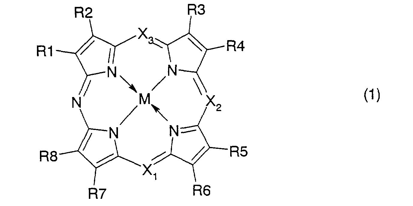
finally found that an azaporphyrin metal complex
with 1 to 4 meso-nitrogen atoms has sharp optical
absorption bands, i.e., a Soret band (blue
region) and a Q band (red region) exhibits proper
balance between a higher refractive index and an
appropriate attenuation coefficient at
wavelengths in these bands and thus in these
wavelengths gives a good reproduction signal,
leading to this invention.
Thus, this invention provides:
According to this invention, a
recording/reproduction signal meeting the DVD
specifications may be obtained and an optical
recording medium capable of recording and/or
reproduction using a blue-violet laser with a
wavelength selected from the range of 390 to 430
nm may be provided.
DETAILED DESCRIPTION OF THE PREFERRED EMBODIMENTS
According to this invention, an
azaporphyrin dye having the above refractive
index n and the above attenuation coefficient k
may be used in a recording layer to provide an
optical recording medium whereby recording and/or
reproduction can be conducted with not only a red
laser at a wavelength of 630 to 680 nm but also a
blue-violet laser at a wavelength of 390 to 430
nm.
An azaporphyrin compound where four
pyrrole rings were cyclized with at least one
nitrogen atom had two large absorption peaks,
i.e., a Soret band having an absorption edge
within the range of 390 to 430 nm of interest and
a Q band having a longer-wavelength side
absorption edge within the range of 630 to 680 nm,
and exhibited high refractive index properties in
both wavelength bands. As the number of meso-nitrogen
atoms increased, an absorption
coefficient in the Q band was increased.
Preferred are here monoazaporphyrin,
diazaporphyrin and triazaporphyrin structures in
which rings are linked via 1 to 3 nitrogen atoms
because the nitrogen number within these limits
may ensure a high refractive index in both red
and blue regions. In this respect, a
diazaporphyrin is particularly preferable. A
porphyrin with no nitrogen atoms does not provide
any intensity of Q band so that a high refractive
index of n>2.0 cannot be achieved in the range of
630 to 680 nm.
In the light of properties of an organic
dye, a recording layer has the following optical
constants; a refractive index n of 2.0 or more,
preferably 2.0 to 2.7 and an attenuation
coefficient of 0.04 to 0.20, preferably 0.04 to
0.15 at a wavelength of λ1 selected from the
range of 630 to 680 nm and n of 1.8 or more,
preferably 2.0 or more and k of 0.30 or less,
preferably 0.20 or less at a wavelength of λ2
selected from the range of 390 to 430 nm.
When λ1 meets n(λ1)<2.0, a recording
signal amplitude cannot be obtained at the
wavelength. Acquiring n(λ1)>2.7 in this kind of
dye is not preferable because it at the same time
requires the condition of k(λ1)>2.0. Furthermore,
when k(λ1)>0.20, an optical absorption becomes so
large, leading to excessive heat generation in a
recording layer so that a fine recording pit
cannot be stably formed. On the contrary, when
k<0.04, recording sensitivity may not be obtained.
Similarly, when n(λ2)<1.8 for a wavelength
λ2, a signal amplitude during recording at a
wavelength λ2 cannot be ensured while when
k(λ2)>0.30, absorption is also increased, leading
to deterioration in a reproduction light signal
at a wavelength λ2.
It is preferable to introduce a
substituent for improving optical properties as a
recording film, durability, solubility and
application properties. In particular, the
azaporphyrin compound tends to be subject to
association, leading to deterioration in optical
properties (a refractive index). It is,
therefore, desirable to introduce a substituent
increasing steric hindrance in the molecule.
Examples of a variety of substituents
which may be introduced as R1 to R8 in this
compound include hydrogen; halogen such as
fluorine, chlorine and bromine; substituted or
unsubstituted alkyl with 1 to 12 carbon atoms
such as methyl, ethyl, n-propyl, iso-propyl, n-butyl,
sec-butyl, tert-butyl, n-pentyl, hexyl,
amyl, cyclohexyl and methylcyclohexyl; aryl with
6 to 20 carbon atoms including aromatic rings
such as phenyl and benzyl; substituted or unsubstituted alkoxy
such as methoxy, ethoxy, propoxy, butoxy, heptoxy and phenoxy;
hydroxyl; substituted or unsubstituted aryloxy; amino or
alkylamino; nitro; cyano; carboxy; substituted or
unsubstituted carboxylate; substituted or
unsubstituted carboxamide; alkylthio; arylthio;
sulfonic; substituted or unsubstituted sulfonate;
substituted or unsubstituted sulfonamide;
substituted or unsubstituted silyl; and siloxy,
which are independently selected. When two or
more of these exist in one molecule, these
substituents may be linked together. The central
metal M represents a transition metal such as Ni,
Co, Cu, Pd, Zn, Mn and Pt. The metal M may be
charged to have a cationic salt structure.
A substrate used in this invention may be
made of any transparent material because
recording/reproduction is conducted with a light.
Examples of a material which may be used include
organic polymers such as polycarbonates,
polyacrylates, polymethacrylates, polystyrene,
polyesters, polyolefins and epoxy resins and
inorganic materials such as glass. A
polycarbonate resin is more preferable because it
exhibits good balance between a light
transmittance and heat resistance and may be
easily molded. A polyolefin having a ring
structure is also preferable because it exhibits
reduced optical anisotropy, lower water
absorptivity and good transparency in a blue-violet
region.
Such a substrate may have, in its surface,
a guide groove or pit for indicating a recording
position and/or a prepit for, for example,
partially read-only data. Such a guide groove or
pit may be generally formed during preparing a
substrate by injection molding, but alternatively
may be formed by, for example, a laser cutting or
2P method.
For stably obtaining a tracking error
output and a good reproduction signal without
distortion even for an HF signal not only at λ1,
a recording/reproduction wavelength for DVD but
also at λ2 selected from the range of 390 to 420
nm which is shorter than λ1, a groove pitch is,
according to the specifications, limited to a
range of 0.7 to 0.85 µm, preferably 0.74 to 0.80
µm for first achieving DVD reproduction
compatibility. When evaluating reproduction
compatibility at λ2 under the pitch conditions,
controlling a half-value width of a groove formed
and an inclination angle in a cross section along
the radius of the groove is important. It was
found that the half-value width and the
inclination angle were suitably within the ranges
of 0.20 to 0.35 µm and 45 to 65 °, respectively.
In terms of a groove has a shape deviated from
these ranges, for example, when a half-value
width was more than 0.35 µm, a tracking error
output could not be ensured at λ2 while when a
half-value width was less than 0.20 µm,
distortion in an HF signal was increased.
Furthermore, when an inclination angle is more
than 65 °, transcription failure reached a
significant level during molding a substrate
while when it is less than 45 °, it became
difficult to ensure a tracking error output at λ2.
A recording layer used in this invention
is basically made of a compound represented by
formula (1), which may be irradiated with a laser
beam to conduct recording. Alternatively, a
recording layer may be made of the dye
represented by formula (1) in combination with
one or more additional dyes or may be made of a
mixture of the dye represented by formula (1) and
another dye in conjunction with a material other
than a photoabsorptive material.
Examples of a dye which may be combined in
this recording layer include macrocyclic
azaannulene dyes such as phthalocyanine dyes,
naphthalocyanine dyes and azaporphyrin dyes with
1 to 4 meso-nitrogen atoms other than the
azaporphyrin represented by formula (1) of this
invention; polymethyne dyes such as cyanine dyes,
melocyanine dyes, squalilium dyes; anthraquinone
dyes; azulenium dyes; azo dyes; and indoaniline
dyes. Among these, particularly preferred are
phthalocyanines exhibiting good durability and
light stability.
A recording layer comprising a dye may be
a monolayer or of a laminated structure of two or
more layers wherein the dye represented by
formula (1) may be used in only one layer or in
two or more layers.
Examples of a dye which may be used in a
lamination structure include macrocyclic
azaannulene dyes such as phthalocyanine dyes,
naphthalocyanine dyes and azaporphyrin dyes;
polymethyne dyes such as cyanine dyes,
melocyanine dyes, squalilium dyes; anthraquinone
dyes; azulenium dyes; azo dyes; and indoaniline
dyes.
The recording layer comprising a dye may
be generally deposited by an appropriate
application method such as spin coating, spray
coating, dip coating and roll coating. Materials
constituting a recording layer including a dye
and a resinous binder may be dissolved in a
solvent which does not harmful to the substrate,
applied to the substrate and then dried.
Preferable examples of a solvent which may be
used include aliphatic or alicyclic hydrocarbons
such as hexane, heptane, octane, decane and
cyclohexane; aromatic hydrocarbons such as
toluene and xylenes; ethers such as diethyl ether,
dibutyl ether and tetrahydrofuran; alcohols such
as methanol, ethanol, isopropanol,
tetrafluoropropanol and methyl cellosolve; and
halogenated compounds such as chloroform,
dichloromethane and 1,2-dichloroethane, which may
be used alone or in combination of two or more.
When depositing two or more recording layers, a
solvent which does not penetrate a previously
applied layer is preferably selected.
A recording layer may be formed by vacuum
deposition, which is effective when a recording
layer material is insoluble in a solvent or a
solvent not harmful to a substrate cannot be
chosen.
A recording layer may have a thickness of
10 nm to 300 nm, desirably 40 nm to 150 nm.
A variety of base layers may be formed
between a recording layer and a substrate for,
e.g., preventing the recording layer from being
deteriorated. For example, a layer made of an
organic material such as polystyrene and
poly(methyl methacrylate) or an inorganic
material such as SiO2 may be used. These may be
used alone or in combination of two or more.
Furthermore, two or more layers may be laminated.
A reflective layer made of a metal such as
Au, Al, Pt, Ag and Ni, or an alloy thereof may be
formed on the above recording layer. In
particular, it is desirable to use gold which is
stable to oxygen or moisture. A reflective layer
may be deposited by an appropriate method such as
vapor-phase deposition, sputtering and ion-plating
to a thickness of 10 nm to 300 nm,
desirably 30 nm to 150 nm.
An intermediate layer may be formed
between a metal reflective layer and a recording
layer for, e.g., improving interlayer adhesion
and increasing a reflectance.
A protective layer may be formed on the
above reflective layer, using, for example, a
polymerizable material such as an acrylate or
methacrylate which may be polymerized by a
general radical reaction and an epoxy which may
be subject to optical cationic polymerization.
These resins may be formed by homopolymerization
or copolymerization with other monomers or
oligomers. These may be dissolved in a solvent
before application. Among these, a UV curing
material is preferable in the light of
workability. A protective layer may be formed by
an appropriate method such as spin coating, dip
coating, bar coating and screen printing and
frequently formed by spin coating because of its
higher workability. The layer may be formed to a
thickness of 1 µm to 100 µm, preferably 1 to 20
µm.
A protective layer thus formed may protect
a recording and a reflective layers, but a more
effective protective layer may be sometimes
needed depending on a status of use. In such a
case, the protective layer may be coated with an
organic material such as a UV curing resin, a
thermosetting resin and a solvent-containing
polymer or an inorganic material such as SiO2,
which may be used alone or in combination of two
or more. Two or more films may be laminated for,
e.g., improving adhesiveness to other layers.
In another structure in this invention, a
first substrate having a recording layer may be
laminated with a second substrate. The second
substrate may be the same as the first substrate.
Alternatively, substrates on which a recording
and a reflective layers have been formed are
laminated together such that the recording layer
sides of the substrates are faced to each other.
Such lamination may be conducted by, e.g., a hot
melt process, a process using a UV curing
adhesive or a process using a one-liquid or two-liquid
mixture type of reactive adhesive.
This invention will be specifically
illustrated with reference to, but not limited to,
Examples.
Example 1
On an injection-molded polycarbonate
substrate having a spiral groove (depth = 150 nm;
half-value width = 0.33 µm; inclination angle: 63
°; pitch = 0.74 µm) with a thickness of 0.6 mm
and a diameter of 120 mm was applied by spin
coating a 20 g/L solution of an diazaporphyrin
metal complex represented by formula (A) in
dimethylcyclohexane at a rotation speed of 2000
rpm to form a recording layer to a thickness of
80 nm on the groove, and the product was dried at
70 °C for 1 hour. On the recording layer was
deposited Au to a thickness of 80 nm using a
sputtering apparatus (Balzers Ltd.; CDI-900).
Then, on the reflective layer was applied a UV
curing resin: SD-17 (Dainippon Ink And Chemicals,
Incorporated) and the layer was cured by UV. On
the surface was laminated another polycarbonate
substrate with a thickness of 0.6 mm as described
above using a radical polymerizable adhesive
(JSR; Z8412H), which was then cured by UV rays to
provide an optical recording medium.
On the optical recording medium was
recorded a repeated signal with a single
frequency whose shortest pit length corresponded
to 0.40 or 0.80 µm, at a linear velocity of 3.5
m/s using a disk tester (PULSTEC INDUSTRIAL
CO.,LTD; DDU1000: wavelength = 658 nm, NA = 0.60).
The signal region was reproduced using a red
laser (650 nm; NA = 0.60) and a violet laser (405
nm; NA = 0.65) to evaluate a reflectance (Rtop),
a modulation degree (HF signal, evaluated by a
pit length) and a CN ratio (CNR). The results
are shown in Table 1.
Example 2
A medium with a film thickness and a
structure on a substrate as described in Example
1 was prepared except using the compound
represented by formula (B) as an organic dye in a
recording layer, and was evaluated for a signal
as described in Example 1. The results are shown
in Table 1.
A medium with a film thickness and a
structure on a substrate as described in Example
1 was prepared except using the compound
represented by formula (C) as an organic dye in a
recording layer, and was evaluated for a signal
as described in Example 1. The results are shown
in Table 1.
Each medium was prepared as described in
Example 1, using a substrate having a spiral
groove of a pitch, a half-value width, an
inclination angle and a depth shown in Table 1.
The results are shown in Table 1.
As shown in Table 1, in the Comparative
Example 1 whose reflective index in 405nm (λ2) is
less than 1.8, a tracking did not start in 405 nm
and recording and reproduction were not
completed. Moreover, even if it is satisfying a
dye optical constant, especially when separating
from the range of substrate groove shape defined
in this invention, recording and reproduction
were inferior to those of Examples in a short
wavelength.
Good recording and reproduction are
attained with two wavelengths, λ1 and λ2, by
adjusting a dye optical constant and substrate
groove shape in a range specified by this
invention.