EP1189156B1 - Computer-assisted design system - Google Patents
Computer-assisted design system Download PDFInfo
- Publication number
- EP1189156B1 EP1189156B1 EP00830557A EP00830557A EP1189156B1 EP 1189156 B1 EP1189156 B1 EP 1189156B1 EP 00830557 A EP00830557 A EP 00830557A EP 00830557 A EP00830557 A EP 00830557A EP 1189156 B1 EP1189156 B1 EP 1189156B1
- Authority
- EP
- European Patent Office
- Prior art keywords
- microstep
- display
- selection
- selection means
- block
- Prior art date
- Legal status (The legal status is an assumption and is not a legal conclusion. Google has not performed a legal analysis and makes no representation as to the accuracy of the status listed.)
- Expired - Lifetime
Links
Images


Classifications
-
- G—PHYSICS
- G06—COMPUTING OR CALCULATING; COUNTING
- G06F—ELECTRIC DIGITAL DATA PROCESSING
- G06F30/00—Computer-aided design [CAD]
-
- G—PHYSICS
- G05—CONTROLLING; REGULATING
- G05B—CONTROL OR REGULATING SYSTEMS IN GENERAL; FUNCTIONAL ELEMENTS OF SUCH SYSTEMS; MONITORING OR TESTING ARRANGEMENTS FOR SUCH SYSTEMS OR ELEMENTS
- G05B2219/00—Program-control systems
- G05B2219/30—Nc systems
- G05B2219/35—Nc in input of data, input till input file format
- G05B2219/35494—Online documentation, manual, procedures, operator, user guidance, assistance
-
- G—PHYSICS
- G05—CONTROLLING; REGULATING
- G05B—CONTROL OR REGULATING SYSTEMS IN GENERAL; FUNCTIONAL ELEMENTS OF SUCH SYSTEMS; MONITORING OR TESTING ARRANGEMENTS FOR SUCH SYSTEMS OR ELEMENTS
- G05B2219/00—Program-control systems
- G05B2219/30—Nc systems
- G05B2219/35—Nc in input of data, input till input file format
- G05B2219/35499—Model of process, machine and parameters
Definitions
- the present invention relates to a computer-assisted design system.
- the computer-assisted design system according to the present invention may be used to advantage by companies, in particular medium-large companies, engaged in the design and possibly also the manufacture of products and/or components.
- the system can be implemented on a known central processing unit connected over a data network (e.g. local data network) to a number of terminal stations (e.g. personal computers), each with a central unit, keyboard, video terminal and mouse.
- a data network e.g. local data network
- terminal stations e.g. personal computers
- Each station is manned by at least one operator.
- Figure 1 shows a simplified block diagram of the operations performed by the system according to the present invention.
- a first block 100 displays a first video page (HOME PAGE, Figure 2a) showing general information about the computer-assisted design system, such as the system name and reference, system title, and any confidentiality clauses governing use of the system and the system-stored data.
- HOME PAGE Figure 2a
- Block 100 allows the operator at least two system operation choices:
- Blocks 110 and 120 are selected using normal graphic environment (e.g. WINDOWS environment) means, i.e. using a mouse to manually position the cursor P at distinct points on the screen corresponding to initiation of the manual inquiry (MANUAL) and system enquiry (SYSTEM) procedures, and then manually operating, e.g. double clicking, the mouse to select block 110 or 120.
- normal graphic environment e.g. WINDOWS environment
- MANUAL manual inquiry
- SYSTEM system enquiry
- block 110 goes back to block 100.
- Block 120 displays a second video page (MAIN PAGE, Figure 2b) from which the operator can choose between at least three operating modes:
- blocks 130, 140, 150 are selected using normal graphic environment (e.g. WINDOWS environment) means, i.e. using a mouse to manually position the cursor P at distinct points on the screen corresponding to the first, second and third operating modes, and then manually operating, e.g. double clicking, the mouse to select block 130, 140 or 150.
- normal graphic environment e.g. WINDOWS environment
- component is intended to mean a distinct physical entity, which may comprise several parts (e.g. a casting, gear, bearing, shaft); while “product” is intended to mean an assembled group of components (e.g. a gearbox comprising a casting and several gears, bearings and shafts).
- Block 130 displays a third video page (PRODUCT PAGE, Figure 2c) showing a list of n standard in-house products, such as:
- Each product in the block 130 list is also selected using normal known graphic environment means.
- block 130 goes on to a block 136, which displays a fourth video page (PRODUCT DEVELOPMENT STEPS PAGE, Figure 2d) showing a list of m steps necessary to develop the standard product selected:
- One or more of the block 136 steps can be selected by the operator, again using known graphic environment selection means.
- block 136 When a given step in the list is selected, block 136 is followed by a block 137, which displays a fifth video page (MICROSTEP PAGE, Figure 2e) showing a number of microsteps, which together define the selected step.
- the order in which the microsteps are listed corresponds to the logical and/or time sequence of the jobs involved in performing the selected step; and each microstep indicates the procedures to be performed in the microstep itself, as characterized by mathematical formulas and input and output parameters.
- microstep sequence and content are based on previous in-house design experience.
- block 137 goes on to a block 139, which provides for expanding the selected microstep, i.e. indicates, in as much detail as the system allows, the operations involved in the microstep according to previous in-house design experience.
- design may be intended in the sense of the ISO 10303 STEP specification, i.e. that company process which commences with identification of customer requirements, and terminates when all the information, tools and materials are available for product manufacture and marketing.
- Expansion of the selected microstep may, for example, comprise displaying tables based on past in-house design experience.
- Block 139 may display for each microstep:
- Block 139 is followed by a block 141 enabling operator access to:
- Block 141 also permits access to a data base (DB) (block 145 after block 141) containing further past in-house design data relative to the microstep parameters. Any other data is selected in a block 146 following block 145, and which also provides for returning to the expanded microstep display in block 139.
- DB data base
- Block 140 displays a sixth video page (COMPONENT PAGE) showing a list of n standard in-house components, such as:
- Each component in the block 140 list is also selected using normal known graphic environment means.
- block 140 goes on to a block 156, which displays a seventh video page (COMPONENT DEVELOPMENT STEPS PAGE) showing a list of m steps necessary to develop the standard component selected, for example:
- One or more of the block 156 steps can be selected by the operator, again using known graphic environment selection means.
- block 156 When a given step in the list is selected, block 156 is followed by a block 157, which displays an eighth video page (MICROSTEP PAGE) showing a number of microsteps, which together define the selected step.
- MICROSTEP PAGE an eighth video page showing a number of microsteps, which together define the selected step.
- the order in which the microsteps are listed corresponds to the logical and/or time sequence of the jobs involved in performing the selected step; and each microstep indicates the procedures to be performed in the microstep itself, as characterized by mathematical formulas and input and output parameters.
- the microstep sequence and content are based on previous in-house design experience.
- block 157 goes on to a block 159, which provides for expanding the selected microstep, i.e. indicates, in as much detail as the system allows, the operations involved in the microstep according to previous in-house design experience.
- Block 159 may display for each microstep:
- Block 159 is followed by a block 160 enabling operator access to:
- Block 160 also permits access to a data base (block 165 after block 160) containing further data relative to the microstep parameters. Any other data is selected in a block 166 following block 165, and which also provides for returning to the expanded microstep display in block 159.
- Block 150 displays a ninth video page (DISCIPLINE PAGE) showing a list of company-related disciplines, such as:
- Each discipline in the block 150 list is also selected using normal known graphic environment means.
- block 150 goes on to a block 170, which displays a tenth video page (DISCIPLINE SUBSECTION SELECTION) showing a list of subsections of the selected discipline:
- a given discipline in the list e.g. material analysis
- Each subsection in the block 170 list is also selected using normal known graphic environment means.
- block 170 supplies detailed technical-scientific information - information used in past design work - relative to the selected subsection of the selected discipline.
- block 170 is followed by a block 177, which provides for:
- the system operator can either select access to the manual (block 110) or make a system inquiry (block 120). If the first operating mode (block 130) is selected, a list of standard in-house products is displayed for selection by the operator. Following selection, the necessary steps to develop the selected product are displayed (block 136); the operator selects the pertinent step (block 136), i.e. the one relevant to current design requirements, and is then provided with the various microsteps indicating as a whole the logical and/or time sequence of design jobs to be performed.
- the system therefore provides for directing and organizing the design work of the operator.
- Each expanded microstep (block 139) provides the operator with further detailed design tools, so that the operator is provided with all the technical "means” by which to do the job.
- the operator is allowed access to:
- the operator also has access to a large data base (block 145) containing further microstep parameter data.
- the system according to the present invention may also be equipped with a processing device featuring meta languages (e.g. XML language) and for automatically receiving into its data base (blocks 145, 165) parameter data relative to a completed project developed according to the system, so that new projects developed according to the system of the present invention provide for automatically loading the data bases.
- a processing device featuring meta languages (e.g. XML language) and for automatically receiving into its data base (blocks 145, 165) parameter data relative to a completed project developed according to the system, so that new projects developed according to the system of the present invention provide for automatically loading the data bases.
- meta languages e.g. XML language
- the data bases of blocks 145 and 165 may be replaced by a single data base accessed by the operator from both blocks 141 and 160.
Landscapes
- Engineering & Computer Science (AREA)
- Physics & Mathematics (AREA)
- Theoretical Computer Science (AREA)
- Computer Hardware Design (AREA)
- Evolutionary Computation (AREA)
- Geometry (AREA)
- General Engineering & Computer Science (AREA)
- General Physics & Mathematics (AREA)
- Management, Administration, Business Operations System, And Electronic Commerce (AREA)
Description
- The present invention relates to a computer-assisted design system.
- As is known, in manufacturing, new products and/or components are normally designed with reference to and by improving and refining earlier design work, which may comprise completed and/or rough projects and associated technical/scientific know-how.
- In large companies, however, all or part of the earlier design work carried out by the company is not always available to design personnel as a whole, so that certain projects, or parts of them, already developed by the company are developed again from scratch, thus resulting in obvious waste in terms of time and human resources.
- US 5,339,247 is cited as prior art.
- Another well-known fact is the extent to which' design work is complicated by difficulties in obtaining access to earlier design work and/or the technical/scientific know-how involved in developing new projects.
- Also known is the extent to which, in most cases, companies are ill-advised to depart from proven design practices.
- It is an object of the present invention to provide a computer-assisted design system enabling complete, troublefree access to company design records, so as to assist and guide design personnel in solving technical problems arising in the course of new projects.
- Further technical problems the present invention is designed to solve include:
- consolidating in-house technical/scientific know-how;
- expediting design procedures;
- improving the performance of newly designed components and/or products;
- cutting design time and cost.
- According to the present invention, there is provided a computer-assisted design system as claimed in Claim 1.
- A preferred, non-limiting embodiment of the invention will be described by way of example with reference to the accompanying drawings, in which:
- Figures 1a, 1b show a block diagram of a computer-assisted design system in accordance with the teachings of the present invention;
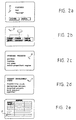
- Figures 2a-2e show video displays relative to the system according to the present invention.
-
- The computer-assisted design system according to the present invention may be used to advantage by companies, in particular medium-large companies, engaged in the design and possibly also the manufacture of products and/or components.
- The system can be implemented on a known central processing unit connected over a data network (e.g. local data network) to a number of terminal stations (e.g. personal computers), each with a central unit, keyboard, video terminal and mouse.
- Each station is manned by at least one operator.
- Figure 1 shows a simplified block diagram of the operations performed by the system according to the present invention.
- To begin with, a
first block 100 displays a first video page (HOME PAGE, Figure 2a) showing general information about the computer-assisted design system, such as the system name and reference, system title, and any confidentiality clauses governing use of the system and the system-stored data. -
Block 100 allows the operator at least two system operation choices: - initiate an inquiry procedure by which to consult
information relative to the overall structure and
operation of the system (
block 110 after block 100) and which, as a whole, defines a system operating manual; - initiate a system inquiry procedure (
block 120 after block 100). -
Blocks block - At the end of the manual inquiry procedure,
block 110 goes back toblock 100. -
Block 120 displays a second video page (MAIN PAGE, Figure 2b) from which the operator can choose between at least three operating modes: - a first operating mode (
block 130 after block 120) wherein the system supplies operating data relative to standard in-house products, i.e. products designed and/or manufactured by the company operating the system; - a second operating mode (
block 140 after block 120) wherein the system supplies operating data relative to standard in-house components, i.e. physical components designed and/or manufactured by the company operating the system; - a third operating mode (
block 150 after block 120) wherein the system supplies operating data relative to scientific disciplines used in the design of standard in-house products and/or components. - In this case, too,
blocks block - More specifically, the term "component" is intended to mean a distinct physical entity, which may comprise several parts (e.g. a casting, gear, bearing, shaft); while "product" is intended to mean an assembled group of components (e.g. a gearbox comprising a casting and several gears, bearings and shafts).
-
Block 130 displays a third video page (PRODUCT PAGE, Figure 2c) showing a list of n standard in-house products, such as: - product 1 (gearbox);
- product 2 (turbine);
- ...
- i-th product (oil pump);
- ...
- n-th product (solid-propellant engine).
- Each product in the
block 130 list is also selected using normal known graphic environment means. - When a given product in the list is selected (e.g. gearbox),
block 130 goes on to ablock 136, which displays a fourth video page (PRODUCT DEVELOPMENT STEPS PAGE, Figure 2d) showing a list of m steps necessary to develop the standard product selected: - step 1 (feasibility study);
- step 2 (definition project);
- step 3 (detailed project);
- i-th step (work project):
- m-1-th step (testing);
- m-th step (approval).
- In the case of the example shown (gearbox),
block 136 indicates the various steps necessary to develop the gearbox : - gearbox feasibility study;
- gearbox definition project;
- detailed gearbox project;
- gearbox work project;
- gearbox testing;
- gearbox approval.
- One or more of the
block 136 steps can be selected by the operator, again using known graphic environment selection means. - When a given step in the list is selected,
block 136 is followed by ablock 137, which displays a fifth video page (MICROSTEP PAGE, Figure 2e) showing a number of microsteps, which together define the selected step. The order in which the microsteps are listed corresponds to the logical and/or time sequence of the jobs involved in performing the selected step; and each microstep indicates the procedures to be performed in the microstep itself, as characterized by mathematical formulas and input and output parameters. - The microstep sequence and content are based on previous in-house design experience.
- When a given microstep in the
block 137 list is selected,block 137 goes on to ablock 139, which provides for expanding the selected microstep, i.e. indicates, in as much detail as the system allows, the operations involved in the microstep according to previous in-house design experience. It should be pointed out that the term "design" may be intended in the sense of the ISO 10303 STEP specification, i.e. that company process which commences with identification of customer requirements, and terminates when all the information, tools and materials are available for product manufacture and marketing. - Expansion of the selected microstep may, for example, comprise displaying tables based on past in-house design experience.
-
Block 139 may display for each microstep: - microstep input parameter tables;
- microstep output parameter tables;
- microstep processing procedures;
- useful microstep tools, e.g. program and processing code lists.
-
Block 139 is followed by ablock 141 enabling operator access to: - block 120 (MAIN block) showing the main video page from which to make a further product, component or discipline option selection;
- block 137 to return to the microstep list display;
- block 139 to expand the microstep.
- Block 141 also permits access to a data base (DB) (block 145 after block 141) containing further past in-house design data relative to the microstep parameters. Any other data is selected in a
block 146 followingblock 145, and which also provides for returning to the expanded microstep display inblock 139. - Block 140 displays a sixth video page (COMPONENT PAGE) showing a list of n standard in-house components, such as:
- component 1 (gear);
- component 2 (shaft);
- ...
- i-th component (casting);
- ...
- n-th component (bearing).
- Each component in the
block 140 list is also selected using normal known graphic environment means. - When a given component in the list is selected (e.g. gear), block 140 goes on to a
block 156, which displays a seventh video page (COMPONENT DEVELOPMENT STEPS PAGE) showing a list of m steps necessary to develop the standard component selected, for example: - gear feasibility study;
- gear definition project;
- detailed gear project;
- gear work project;
- gear testing;
- gear approval.
- One or more of the
block 156 steps can be selected by the operator, again using known graphic environment selection means. - When a given step in the list is selected, block 156 is followed by a
block 157, which displays an eighth video page (MICROSTEP PAGE) showing a number of microsteps, which together define the selected step. The order in which the microsteps are listed corresponds to the logical and/or time sequence of the jobs involved in performing the selected step; and each microstep indicates the procedures to be performed in the microstep itself, as characterized by mathematical formulas and input and output parameters. The microstep sequence and content are based on previous in-house design experience. - When a given microstep in the list is selected, block 157 goes on to a
block 159, which provides for expanding the selected microstep, i.e. indicates, in as much detail as the system allows, the operations involved in the microstep according to previous in-house design experience. -
Block 159 may display for each microstep: - microstep input parameter tables;
- microstep output parameter tables;
- microstep processing procedures;
- useful microstep tools, e.g. program and processing code lists.
-
Block 159 is followed by ablock 160 enabling operator access to: - block 120 (MAIN block) showing the main video page from which to make a further product, component or discipline option selection;
- block 157 to return to the microstep list display;
- block 159 to expand the microstep.
- Block 160 also permits access to a data base (block 165 after block 160) containing further data relative to the microstep parameters. Any other data is selected in a
block 166 followingblock 165, and which also provides for returning to the expanded microstep display inblock 159. - Block 150 displays a ninth video page (DISCIPLINE PAGE) showing a list of company-related disciplines, such as:
- discipline 1 (material analysis);
- discipline 2 (thermostructural analysis);
- ...
- i-th discipline (thermodynamics);
- ...
- k-th discipline (mechanical project).
- Each discipline in the
block 150 list is also selected using normal known graphic environment means. - When a given discipline in the list is selected (e.g. material analysis), block 150 goes on to a
block 170, which displays a tenth video page (DISCIPLINE SUBSECTION SELECTION) showing a list of subsections of the selected discipline: - subsection 1 (basics);
- subsection 2 (tools);
- ...
- i-th subsection (applications);
- ...
- 1-th subsection.
- Each subsection in the
block 170 list is also selected using normal known graphic environment means. - When a given subsection in the list is selected, block 170 supplies detailed technical-scientific information - information used in past design work - relative to the selected subsection of the selected discipline.
- Once the
block 170 inquiry is completed, block 170 is followed by ablock 177, which provides for: - returning to the discipline list (block 150);
- returning to block 120.
- In actual use, after activating the system, the system operator can either select access to the manual (block 110) or make a system inquiry (block 120). If the first operating mode (block 130) is selected, a list of standard in-house products is displayed for selection by the operator. Following selection, the necessary steps to develop the selected product are displayed (block 136); the operator selects the pertinent step (block 136), i.e. the one relevant to current design requirements, and is then provided with the various microsteps indicating as a whole the logical and/or time sequence of design jobs to be performed.
- The system therefore provides for directing and organizing the design work of the operator.
- Each expanded microstep (block 139) provides the operator with further detailed design tools, so that the operator is provided with all the technical "means" by which to do the job.
- In particular, the operator is allowed access to:
- microstep input parameter tables;
- microstep output parameter tables;
- microstep processing procedures;
- useful microstep tools, e.g. program and processing code lists.
- The operator also has access to a large data base (block 145) containing further microstep parameter data.
- Moreover, the tools and data supplied are "proven", by having already been used in earlier in-house design work, which is thus made available to simplify, improve and expedite the design work of the operator, and to ensure this conforms with consolidated in-house design practices. The same obviously also applies to selection of
block 140 and following blocks 156-166. - The system according to the present invention may also be equipped with a processing device featuring meta languages (e.g. XML language) and for automatically receiving into its data base (
blocks 145, 165) parameter data relative to a completed project developed according to the system, so that new projects developed according to the system of the present invention provide for automatically loading the data bases. - Alternatively, the data bases of
blocks blocks
Claims (10)
- A computer-assisted design system for use by a company, comprising:first display and selection means (130) for commanding the video display (PRODUCT PAGE) of a list of standard in-house products; said first display and selection means (130) permitting selection of the various standard displayed products;second display and selection means (136), which are activated following selection of a said displayed product to command the video display (PRODUCT STEP PAGE) of a list of steps necessary to develop the selected standard product; said second display and selection means (136) permitting selection of the various displayed steps; characterised by further comprising:third display and selection means (137), which are activated following selection of a said displayed step to command display (MICROSTEP PAGE) of a number of microsteps defining, as a whole, the previously selected step; the order of said microsteps corresponding to the logical and/or time sequence of the jobs involved in performing the selected step; each microstep indicating the procedures to be performed in the microstep, as characterized by formulas, input parameters and output parameters; and said sequence of microsteps being based on in-house design experience to provide an operator using said system with technical information which may be used in designing said product.
- A system as claimed in Claim 1, characterized by also comprising first selection means for selecting said microsteps and permitting selection of at least one microstep to select first expansion means (139) for expanding the selected microstep and displaying, in as much detail as the system allows, the operations defined by the microstep on the basis of in-house design experience.
- A system as claimed in Claim 2, characterized in that said first expansion means (139) display for each microstep:tables of input parameters by which to perform the microstep;tables of output parameters by which to perform the microstep;processing procedures by which to perform the operations in the microstep; andtools for use in the microstep, such as a program list and a processing code list.
- A system as claimed in Claim 3, characterized in that said first expansion means (139) permit access (141) to a data base (145) in which is stored further previous in-house experience data relative to the microstep parameters.
- A system as claimed in any one of the foregoing Claims, characterized by comprising:fourth display and selection means (140) for commanding the video display (COMPONENT PAGE) of a list of standard in-house components; said fourth display and selection means (140) permitting selection of the various standard displayed components;fifth display and selection means (156), which are activated following selection of a said displayed component to command the video display (COMPONENT STEP PAGE) of a list of steps necessary to develop the selected standard component; said fifth display and selection means (156) permitting selection of the various displayed steps;sixth display and selection means (157), which are activated following selection of a said displayed step to command display (MICROSTEP PAGE) of a number of microsteps defining, as a whole, the previously selected step; the order of said microsteps corresponding to the logical and/or time sequence of the jobs involved in performing the selected step; each microstep indicating the procedures to be performed in the microstep, as characterized by formulas, input parameters and output parameters; and said sequence of microsteps being based on in-house design experience to provide an operator using said system with technical information which may be used in designing said component.
- A system as claimed in Claim 5, characterized by also comprising second selection means for selecting said microsteps and permitting selection of at least one microstep to select second expansion means for expanding the selected microstep and displaying, in as much detail as the system allows, the operations defined by the microstep on the basis of previous in-house design experience.
- A system as claimed in Claim 5, characterized in that said second expansion means (159) display for each microstep:tables of input parameters by which to perform the microstep;tables of output parameters by which to perform the microstep;processing procedures by which to perform the operations in the microstep;tools for use in the microstep, such as a program list and a processing code list.
- A system as claimed in Claim 7, characterized in that said second expansion means (159) permit access (160) to a data base (165) in which is stored further previous in-house experience data relative to the microstep parameters.
- A system as claimed in any one of the foregoing Claims, characterized by comprising:seventh display and selection means (150) for displaying a list of company-related scientific disciplines; said seventh display and selection means (150) permitting selection of the various displayed disciplines; andeighth display and selection means (170), which are activated following selection of a said discipline to command the video display (DISCIPLINE SUBSECTION SELECTION) of a number of subsections of the selected discipline; said eighth display and selection means (170) permitting selection of the various displayed subsections to provide detailed technical-scientific information relative to the selected subsection of the previously selected discipline.
- A system as claimed in any one of the foregoing Claims, characterized by comprising a processing device having meta languages, in particular the XML language, and for automatically receiving into its data base (145, 165) data relative to the parameters of a completed project developed according to said system, so that new projects developed according to said system of the present invention provide for automatically loading said data base.
Priority Applications (2)
| Application Number | Priority Date | Filing Date | Title |
|---|---|---|---|
| DE60005951T DE60005951T2 (en) | 2000-08-03 | 2000-08-03 | Computer-aided design system |
| EP00830557A EP1189156B1 (en) | 2000-08-03 | 2000-08-03 | Computer-assisted design system |
Applications Claiming Priority (1)
| Application Number | Priority Date | Filing Date | Title |
|---|---|---|---|
| EP00830557A EP1189156B1 (en) | 2000-08-03 | 2000-08-03 | Computer-assisted design system |
Publications (2)
| Publication Number | Publication Date |
|---|---|
| EP1189156A1 EP1189156A1 (en) | 2002-03-20 |
| EP1189156B1 true EP1189156B1 (en) | 2003-10-15 |
Family
ID=8175438
Family Applications (1)
| Application Number | Title | Priority Date | Filing Date |
|---|---|---|---|
| EP00830557A Expired - Lifetime EP1189156B1 (en) | 2000-08-03 | 2000-08-03 | Computer-assisted design system |
Country Status (2)
| Country | Link |
|---|---|
| EP (1) | EP1189156B1 (en) |
| DE (1) | DE60005951T2 (en) |
Family Cites Families (2)
| Publication number | Priority date | Publication date | Assignee | Title |
|---|---|---|---|---|
| EP0451371B1 (en) * | 1990-04-13 | 1997-11-26 | Koninklijke Philips Electronics N.V. | A method for organizing and accessing product describing data pertaining to an engineering process |
| JP3064469B2 (en) * | 1991-04-19 | 2000-07-12 | 株式会社日立製作所 | CAD parts management system |
-
2000
- 2000-08-03 EP EP00830557A patent/EP1189156B1/en not_active Expired - Lifetime
- 2000-08-03 DE DE60005951T patent/DE60005951T2/en not_active Expired - Fee Related
Also Published As
| Publication number | Publication date |
|---|---|
| DE60005951T2 (en) | 2005-01-27 |
| EP1189156A1 (en) | 2002-03-20 |
| DE60005951D1 (en) | 2003-11-20 |
Similar Documents
| Publication | Publication Date | Title |
|---|---|---|
| US7571392B2 (en) | User definable task based interface | |
| US4862376A (en) | Bill of material interface to CAD/CAM environment | |
| US5167011A (en) | Method for coodinating information storage and retrieval | |
| US7092934B1 (en) | Method and apparatus for associating information with an object in a file | |
| US6901407B2 (en) | System and method for updating project management scheduling charts | |
| US7260772B2 (en) | System and method for creating a pert chart | |
| US20050235224A1 (en) | User interface for an activity scout window | |
| US20080243930A1 (en) | System and Method for Automated Customization of a Workflow Management System | |
| US20050235206A1 (en) | User interface for a quick activity window | |
| US8151202B1 (en) | Providing a workflow guide | |
| US20050235208A1 (en) | User interface for a guided activity window | |
| EP1435569A2 (en) | Method and apparatus for localization of applications | |
| US20050235223A1 (en) | User interface adaptable by an end user | |
| EP1109092A1 (en) | File system navigation | |
| EP2626794A1 (en) | Character conversion system and character conversion method and computer program | |
| WO2000054185A1 (en) | Method and apparatus for building a user-defined technical thesaurus using on-line databases | |
| US20020075328A1 (en) | Contextual and dynamic command navigator for CAD and related systems | |
| US20050086044A1 (en) | System and method of identifying a translation resource | |
| US20040051737A1 (en) | Method and system of interface editing and online real-time accessing for a personal mobile device | |
| US20170076243A1 (en) | Profile searching and matching system | |
| JP3926496B2 (en) | Project management system | |
| EP1189156A1 (en) | Computer-assisted design system | |
| US6260046B1 (en) | Product architecture retrieval information system | |
| JP7230393B2 (en) | Design support device, program | |
| JP2000099522A (en) | Dictionary lookup system for multiple dictionaries and program recording medium |
Legal Events
| Date | Code | Title | Description |
|---|---|---|---|
| PUAI | Public reference made under article 153(3) epc to a published international application that has entered the european phase |
Free format text: ORIGINAL CODE: 0009012 |
|
| AK | Designated contracting states |
Kind code of ref document: A1 Designated state(s): AT BE CH CY DE DK ES FI FR GB GR IE IT LI LU MC NL PT SE Kind code of ref document: A1 Designated state(s): DE FR GB IT |
|
| AX | Request for extension of the european patent |
Free format text: AL;LT;LV;MK;RO;SI |
|
| GRAH | Despatch of communication of intention to grant a patent |
Free format text: ORIGINAL CODE: EPIDOS IGRA |
|
| 17P | Request for examination filed |
Effective date: 20020918 |
|
| AKX | Designation fees paid |
Free format text: DE FR GB IT |
|
| GRAH | Despatch of communication of intention to grant a patent |
Free format text: ORIGINAL CODE: EPIDOS IGRA |
|
| GRAA | (expected) grant |
Free format text: ORIGINAL CODE: 0009210 |
|
| AK | Designated contracting states |
Kind code of ref document: B1 Designated state(s): DE FR GB IT |
|
| REG | Reference to a national code |
Ref country code: GB Ref legal event code: FG4D |
|
| REG | Reference to a national code |
Ref country code: IE Ref legal event code: FG4D |
|
| REF | Corresponds to: |
Ref document number: 60005951 Country of ref document: DE Date of ref document: 20031120 Kind code of ref document: P |
|
| RAP2 | Party data changed (patent owner data changed or rights of a patent transferred) |
Owner name: AVIO S.P.A. |
|
| REG | Reference to a national code |
Ref country code: GB Ref legal event code: 732E |
|
| ET | Fr: translation filed | ||
| PG25 | Lapsed in a contracting state [announced via postgrant information from national office to epo] |
Ref country code: GB Free format text: LAPSE BECAUSE OF NON-PAYMENT OF DUE FEES Effective date: 20040803 |
|
| PLBE | No opposition filed within time limit |
Free format text: ORIGINAL CODE: 0009261 |
|
| STAA | Information on the status of an ep patent application or granted ep patent |
Free format text: STATUS: NO OPPOSITION FILED WITHIN TIME LIMIT |
|
| 26N | No opposition filed |
Effective date: 20040716 |
|
| PG25 | Lapsed in a contracting state [announced via postgrant information from national office to epo] |
Ref country code: DE Free format text: LAPSE BECAUSE OF NON-PAYMENT OF DUE FEES Effective date: 20050301 |
|
| GBPC | Gb: european patent ceased through non-payment of renewal fee |
Effective date: 20040803 |
|
| PG25 | Lapsed in a contracting state [announced via postgrant information from national office to epo] |
Ref country code: FR Free format text: LAPSE BECAUSE OF NON-PAYMENT OF DUE FEES Effective date: 20050429 |
|
| REG | Reference to a national code |
Ref country code: IE Ref legal event code: MM4A |
|
| REG | Reference to a national code |
Ref country code: FR Ref legal event code: ST |
|
| PG25 | Lapsed in a contracting state [announced via postgrant information from national office to epo] |
Ref country code: IT Free format text: LAPSE BECAUSE OF NON-PAYMENT OF DUE FEES Effective date: 20050803 |