EP1189126A2 - Method for monitoring an installation - Google Patents
Method for monitoring an installation Download PDFInfo
- Publication number
- EP1189126A2 EP1189126A2 EP01810783A EP01810783A EP1189126A2 EP 1189126 A2 EP1189126 A2 EP 1189126A2 EP 01810783 A EP01810783 A EP 01810783A EP 01810783 A EP01810783 A EP 01810783A EP 1189126 A2 EP1189126 A2 EP 1189126A2
- Authority
- EP
- European Patent Office
- Prior art keywords
- model
- value
- variables
- operating
- sizes
- Prior art date
- Legal status (The legal status is an assumption and is not a legal conclusion. Google has not performed a legal analysis and makes no representation as to the accuracy of the status listed.)
- Granted
Links
Images

Classifications
-
- G—PHYSICS
- G05—CONTROLLING; REGULATING
- G05B—CONTROL OR REGULATING SYSTEMS IN GENERAL; FUNCTIONAL ELEMENTS OF SUCH SYSTEMS; MONITORING OR TESTING ARRANGEMENTS FOR SUCH SYSTEMS OR ELEMENTS
- G05B23/00—Testing or monitoring of control systems or parts thereof
- G05B23/02—Electric testing or monitoring
- G05B23/0205—Electric testing or monitoring by means of a monitoring system capable of detecting and responding to faults
- G05B23/0218—Electric testing or monitoring by means of a monitoring system capable of detecting and responding to faults characterised by the fault detection method dealing with either existing or incipient faults
- G05B23/0221—Preprocessing measurements, e.g. data collection rate adjustment; Standardization of measurements; Time series or signal analysis, e.g. frequency analysis or wavelets; Trustworthiness of measurements; Indexes therefor; Measurements using easily measured parameters to estimate parameters difficult to measure; Virtual sensor creation; De-noising; Sensor fusion; Unconventional preprocessing inherently present in specific fault detection methods like PCA-based methods
-
- G—PHYSICS
- G05—CONTROLLING; REGULATING
- G05B—CONTROL OR REGULATING SYSTEMS IN GENERAL; FUNCTIONAL ELEMENTS OF SUCH SYSTEMS; MONITORING OR TESTING ARRANGEMENTS FOR SUCH SYSTEMS OR ELEMENTS
- G05B17/00—Systems involving the use of models or simulators of said systems
- G05B17/02—Systems involving the use of models or simulators of said systems electric
Definitions
- the invention relates to a method for monitoring a system several subsystems according to the generic term of the independent Claim.
- Plants such as water or gas turbines with downstream Generators for generating electrical energy in power plants, turbo and Piston compressors for the compression of gases, pump systems or Aircraft engines are typically quite complex systems that are commonly used different working points and their respective operating status is influenced by a large number of process variables. It is in the Usually necessary to monitor the condition of such facilities Malfunctions, that means deviations from the normal Operational behavior, to detect as early as possible, or in order to To monitor the wear status of individual components necessary maintenance work planned in time and carried out efficiently can be.
- a monitoring method is therefore described in EP-A-0 895 197 proposed that is based on experimental modeling, so without a preliminary calculation of the physical relationships between the process variables.
- Measured values are recorded for a defined set of process variables.
- modeling phase are for the Process variables for as many different working points as possible recorded, checking that the system during this Modeling phase works trouble-free.
- Based on the during the Modeling phase of the measured values is an experimental model for created the operational behavior, taking the input variables of the model are at least part of the set of process variables and the Output variables a model value for at least one of the process variables include.
- the normal operating phase of the plant is using of the model for the operating behavior at predefinable time intervals determines at least one monitoring variable that is independent of the respective current working point.
- This monitoring variable is preferably that Residual, which is the difference from the current measured value and the corresponding model value.
- the time course of the Monitoring size is used to assess wear in the Subsystems of the system and / or for the detection of malfunctions used.
- EP-A-0 895 197 has the advantage that it can be used in essentially does without physical modeling and therefore very much simple and suitable for industrial applications. moreover it takes into account the current operating point of the system and can also slowly progressing changes, such as those caused by Wear caused, recognize early. This allows reliably monitor even complex systems. It is also an efficient one Planning of maintenance work possible, which leads to a reduction in Maintenance and operating costs.
- the method according to the invention thus comprises the following steps: During the operation of the plant are for a set set of Process variables at predeterminable time intervals each of measured values detected. Those recorded in a learning phase for various work points Measured values are used to create models for the operating behavior of the Subsystems used, with the input variables of each model are at least a part of the process variables and the output variable of each Model includes a model value for at least one of the process variables and wherein the models are compared by comparing the model values with the Measured values can be optimized.
- the Models in predefinable time intervals at least one Monitoring size determined, regardless of the current Working point is and the time course of the monitoring variable becomes Monitoring of the system used. Before determining the A monitoring test is carried out in which it is checked whether at least the measured values for those process variables the operating sizes are within a predetermined range.
- the method according to the invention is therefore based on the fact that the measured values subjected to a preliminary test for the operating and / or environmental parameters before being used as inputs for the specific models for the different subsystems can be used.
- company sizes are The process variables that mean the operating state of the entire system, which is not specific for one individual subsystem.
- environmental sizes are those Process variables meant, which at least approximately not by the Operation of the system can be influenced, for example the air temperature outside the facility. Because usually in every specific model for that Operating behavior of a subsystem at least one size as Input variable, can be checked by pre-checking the measured values for The company variables prevent incorrect input variables for the models of the subsystems are used. So it is guaranteed that only those models are evaluated for the subsystems that interference-free environmental and operating parameters as input parameters exhibit.
- the Subsystems with the operating or Environmental sizes to be checked is also an easier one Fault isolation or fault identification possible.
- the error shows up namely during the preliminary test, one of the measured values of the Company sizes may be faulty or when determining a An error has occurred measured value for an environmental variable.
- the method according to the invention thus performs the monitoring, so to speak divided in two by.
- the company sizes which describe the operating status of the entire system and only then will the company sizes classified as trouble-free the specific models for the operating behavior of the subsystems evaluated. This makes it possible to reliably differentiate whether the Deviation from normal operating behavior only by a subsystem or by multiple subsystems or by a faulty one Company size or an environmental size is caused.
- a machine model is preferably determined for the preliminary test Input variables are company variables and their output variables are one Include machine model value for at least one of the company variables.
- Such a machine model represents a relatively simple and represents a reliable method to determine the size of the company for errors check.
- the machine model has at least one model with which a machine model value for the deviation of the Measured value for an operating variable from a theoretically determined target value is determined for this company size. So with this model the deviation of the current measured value from a theoretical one modeled certain target value. Then this model value for the Deviation compared to the actual value of the deviation. It has it has been shown that the deviation of the measured value from the makes it much easier to model theoretical value and one Model delivers more reliable statements.
- the determined target value is preferably an experimental model which is created and optimized based on the measured values recorded in the learning phase.
- the machine model can be created in the same or a similar way like the models for the operating behavior of the subsystems.
- the machine model can be created based on the measured values that in the learning phase for different working points, whereby by Compare the machine model value with the corresponding one actual measured value a deviation quantity is determined, and Model parameters of the machine model are optimized so that one out the variability of determinable model errors becomes minimal.
- the environmental parameters are also preferably used during the preliminary test Checked for freedom from interference, for example by redundant measurement or through plausibility checks.
- the preliminary test includes a range test in which is checked whether individual or combinations of Company sizes within the range of Working points. This can prevent "Unlearned" states of the system lead to false warnings.
- Another advantageous measure is when at least one Monitoring size a confidence level is set, this Confidence can be increased if the surveillance size leaves the original area of trust, and the enlargement of the Trust area is registered. This measure will Operating personnel early on, for example Signs of wear carefully, so that maintenance work in time can be planned.
- the Monitoring system around a turbine with a driven by this Generator for generating electrical energy acts as in Hydroelectric power plants are used.
- the invention is not based on limited such applications that the system to be monitored can for example also be a gas turbine with a generator connected downstream, a turbo or piston compressor for compressing gases, one Pump system or an aircraft engine.
- subsystem are parts of the system, subsystems or individual Components, which are described by process variables, between which there is a physical connection. It can such a subsystem is a concrete constructive one coherent component system, for example the component system Act "axial bearing”, which, for. B. by different storage temperatures is marked as process variables. But it can also be a act functionally related subsystem, for example Subsystem “cooled thrust bearing”, which except through the Storage temperatures through further process variables, such as B. oil temperature, Cooling water temperature and performance is marked.
- process variable is generally a variable from one
- the totality of physical quantities means the totality in this application the operating state of the system and its partial or Describes subsystems.
- the process variables are therefore immediate or indirectly measurable quantities that characterize the Operating state of the system or its subsystems are useful or have an influence on the operating state of the system.
- process size for example the following sizes: power, stator position, Impeller position, net head of water, pressure in front of and behind the Turbine, water flow rate, water temperature, speed the turbine, temperature of the cooling medium, temperature in the generator, Temperatures in shaft bearings or seals, noise emissions, Vibrations, blade positions etc.
- Some of the process sizes are from Operating personnel can be influenced directly, such as the Flow rate of water through the turbine, other process sizes, such as for example the temperature in the shaft bearing or in the shaft seal, on the other hand, cannot be influenced directly.
- Process variables which are not all independent of each other, however usually have a strong correlation.
- the environmental variables are such process variables, which approximately not influenced by the operation of the system, for example the water temperature in the inlet or the air temperature outside the facility or the building in which the facility is located located.
- the company variables are those process variables that the Describe the operating status of the entire system.
- the company sizes have the property that they are approximately uncorrelated to the Environmental sizes are approximate, and that between them there are static relationships. Examples of company sizes are the Power, the stator position, the impeller position, the drop height of the water, the flow rate or the efficiency.
- the component sizes are those process sizes that are not environmental or company sizes. They are sizes that are specific to one Subsystems are, for example storage temperatures, process variables which describe the oil lubrication and oil cooling system, oil pressure. component sizes can be local, that is, limited to the subsystem that they describe the importance of company variables for this subsystem gain.
- the "operating point” or “operating point” is the operating state meant where the system is currently working. Each with the facility feasible combination of process variables corresponds to one Operating point. The total of the possible working points is called Operating area designated. The working point of the system is usually Can be specified by the operating personnel by directly influencing process variables can be set to the desired value. The turbine is running For example, in part-load mode, it works on another Working point than in full load operation. The working point of the plant is through the Operating and environmental sizes set.
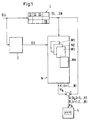
- the too monitoring system so here is the turbine generator unit designated as a whole by the reference number 1 and comprises a total of N Subsystems 11, 12, ..., 1N where N is any natural number.
- through Sensors not shown, are used during the operation of the system 1 for a fixed set of process variables B, U, S1, S2, ..., SN in Predefinable time intervals, for example every minute or every 10 Minutes, measured values recorded.
- the process variables B are company variables, for example the flow, the impeller position, the stator position, the electrical terminal power of the generator, the net head of the water.
- the process variables U are environmental variables, for example the Temperature of the ambient air or the water temperature in the inlet.
- each model Mi has as input variables in addition to the component sizes Si of this subsystem 1i at least one but usually several of the company sizes B and optionally one or more environmental variables U. Die Company sizes B therefore go into several or all of the Mi models.
- a model Mi is therefore created for each subsystem 1i.
- the entirety of the models Mi is designated M in FIG. 1.
- monitoring variables Ri 1,2, ..., N are determined, which are independent of the the respective operating point of the system.
- the Monitoring variables Ri each residuals, which are formed by difference from the current measured values for the component sizes Si and associated model values Yi.
- the time course of the monitoring variables Ri becomes monitoring and used to diagnose the system.
- the Time course of the monitoring variables Ri on an output unit 4 represented graphically.
- Based on the time course of the Monitoring parameters Ri can be used to assess wear and tear malfunctions are detected. With wear are there operational, usually slow-moving changes meant, for example in the shaft bearing or in the shaft seals as well z.
- a preliminary test 2 is carried out, in which it is checked whether at least the Measured values for those process variables that are company variables B, are within a predetermined range. Through this measure the efficiency of the process can be increased significantly. Because in the Operating phase of system 1 the current measured values for the operating parameters B are checked in each case before the models Mi for the subsystems 1i are evaluated, it is prevented that errors in the Propagate farm sizes B in models Mi for subsystems 1i and lead to false alarms or misdiagnoses. In addition, the Preliminary test 2 and the subsequent processing of the Mi models for the Subsystems 1i the identification of faulty process variables (fault isolation) reliably and easily.
- Preliminary check 2 of company sizes B also increases reliability wear monitoring for the individual subsystems 1i and facilitated thus clearly planning maintenance work.
- the method according to the invention can be divided into two Divide phases, namely into a learning phase and an operating phase.
- the Learning phase is used to create the models Mi for the subsystems 1i and
- system 1 is monitored using the Mi models. How the models Mi for the subsystems 1i based on those in the learning phase the measured values determined for the process variables can be determined in the EP-A-0 895 197 already cited is explained in detail and is therefore only described here briefly outlined. For more information, see EP-A-0 895 197, which is hereby incorporated into the present description.
- the Models Mi are the measured values for the process variables B, U, S1, ..., SN used, which are recorded during the learning phase.
- the learning phase denotes a time-limited operating period of the system 1, during which the system 1 in normal, that is, trouble-free operation is working.
- the choice of the learning phase can be based on experience. For example, after commissioning or a revision of the system 1 waited until typical running-in processes have been completed.
- the Learning phase is chosen so long that it has several different Includes operating points from the operating area of system 1 During the learning phase, the system is used on a variety of different Operating points operated, always ensured by checks is that the system 1 works correctly during the learning phase or that only such measured values are used to create the Mi models are, with the detection of the plant 1 worked error-free and trouble-free Has.
- At least one of the component sizes is selected from the set of component sizes Si that describe this subsystem 1i Si k is called.
- a model value Yi k is determined using the model Mi.
- At least some of the component sizes Si of this subsystem 1i as well as operating parameters B and possibly also environmental variables U are used as input variables of the model Mi.
- the case is explained below by way of example that exactly one of the component sizes, namely Si k , is the initial size of the model Mi.
- a linear static model structure is selected as the model structure for the model Mi, that is to say the process variable Si k is represented as a linear combination of the input variables of the model Mi.
- the coefficients of this linear combination denoted by a m , where m is a running index, are the model parameters for the model Mi.
- the sets (B, U, Si) T of measured values provide the determination equations for the model parameters a m . Since the number of sets of measured values is generally considerably larger than the number of model parameters a m , the system of the determination equations is over-determined. However, sufficient mathematical methods are known to use the determination equations to determine the best possible values for the model parameters a m . For example, methods of compensation calculation, the method of least squares, the method of singular value decomposition (SVD) or the principal component analysis (PCA) are suitable. Since such methods are well known, they are not explained in more detail here.
- Means of the model Mi, the associated model value (Yi k) T as the linear combination of the process parameters B, U, Si is now determined by the coefficients a m for each set (B, U, Si) T.
- the (Yi k ) T form a set of model values, where (Yi k ) T is the model value for the component size Si k for the time T.
- the model values (Yi k ) T are compared with the corresponding actual measured values for the component size (Si k ) T by forming a difference, and a residual r T is determined from each.
- a model error ⁇ is determined from the totality of the residuals r T , which is a measure of the quality of the model Mi.
- the model error ⁇ can be, for example, the normalized sum of the squares of the residuals.
- the model Mi is optimized by determining the model parameters a m and each time again determining the model error ⁇ until the model error ⁇ is minimal or falls below a predetermined limit. If this is achieved, the Mi model is sufficiently good for monitoring.
- the fluctuations in the residuals r T determined during the learning phase represent how large the deviation of the model value Yi k from the actual measured value Si k is typically. Therefore, in the normal operating phase, the confidence limits of the models or the threshold values for the monitoring variable are preferably determined on the basis of the residuals r T determined in the learning phase.
- the model structures used generally have no physical ones Importance.
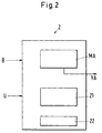
- the preliminary test 2 includes the following components: a machine model MA, its input variables Company sizes B and their output sizes are one Include machine model value YA for at least one of the operating variables; a range test 21, in which it is checked whether individual or Combinations of company sizes within the in the learning phase learned range of working points; a test 22, with which the Environmental variables are checked for freedom from interference.
- the MA machine model is essentially based on the same concept like the Mi models for the 1i subsystems.
- the machine model MA has as Input sizes Operating sizes B, for at regular intervals Measured values are recorded using the sensors.
- the task of MA machine model is selected for one or more Operating parameters to calculate machine model values, which then with the corresponding measured values for the operating parameters are compared can.
- the machine model MA only for exactly one selected company size B calculates a machine model value YA. It goes without saying that in practice for more than one company size B machine model values can be calculated, for which more than one machine model can be provided.
- Expediently with the Machine model or the machine models MA for those Operating parameters B machine model values YA calculated, which as Input sizes for models Mi of subsystems 1i can be used.
- the machine model MA like the models Mi, is based on the subsystem of measured values, which are recorded during the learning phase and saved.
- the machine model is therefore preferred Unlike the Mi models, MA is not a purely experimental model, but also takes into account known physical relationships between company sizes B and previous knowledge of plant 1.
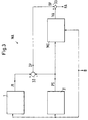
- FIG. 3 shows a concrete exemplary embodiment for the implementation of the Machine model MA schematically illustrated. It serves the Operating variable P, which is the electrical terminal power of the generator is to check that there is no interference. With Pl the actual value of the company size Denoted P, which can be measured, and with PS the target value of P, theoretically based on basic and prior knowledge, in Dependency on operating variables B is calculated. This target value PS is theoretically calculated by a module 31.
- the module 31 can for example include a physical model. It is also possible that the module 31 known physical relationships or empirically determined relationships between company sizes or prior knowledge of Plant 1 evaluates.
- the module 31 supplies a theoretical target value PS for the terminal power as a function of the operating parameters of the impeller position LA, stator position LE and net head HN, their current values recorded by measurement. With this calculation, more Sizes are taken into account, such as the numerical description of the Efficiency shell curves ⁇ h (LA, LE, HN) of the turbine, the efficiency ⁇ g of the generator and mechanical losses PM.
- the difference DP becomes metrological recorded actual value Pl and the theoretically calculated target value PS determined.
- This difference DP is also an operating variable B, which is here The embodiment described serves the freedom from interference Check company size P.
- Model parameters b0, b1, b2, b3, b4 of the model ME determined and optimized.
- the model ME is thus an experimental model with which the Deviation DP of the operating variable P from a theoretically determined target value is modeled.
- a large number of sets (LE, LA, HN, PI) T of measured values for the operating variables LE, LA, HN, PI are collected and stored, the index T being the successive sets of measured values (LE, LA, HN, PI) T indexed.
- the module 31 calculates the associated theoretical target value (PS) T.
- PS theoretical target value
- the sets (LE, LA, HN) T together with the associated value (PS) T provide the determination equations for the model parameters b0 to b4.
- a machine model value (YA) T for the deviation of the actual value Pl of the power from the target value PS of the power can then be determined for each index T.
- a model error ⁇ is determined from the totality of the residuals ⁇ T , which is a measure of the quality of the model ME.
- the model error ⁇ can be, for example, the normalized sum of the squares of the residuals.
- the model ME optimized until the model error ⁇ is minimal or a predetermined one Falls below the limit. If this is achieved, the ME model is good enough.
- the current machine model value YA for the difference DP between the measured power Pl and the Target value PS of the power determined.
- This machine model value YA is with the corresponding current measured value of this operating variable DP compared and a residual RA for plant 1 is determined, z. B. by Difference formation (point 33 in Fig. 3).
- This residual RA represents one Monitoring variable. Is the residual RA within a predetermined area, the so-called trust area, so the Company size P classified as trouble-free or error-free. Otherwise, there is a warning as will be explained later.
- warnings can be, for example: A malfunction due to HN contamination of bores and pipes or due to Air pocket; Disorders of LA or LE; Disturbance in the measurement of the Performance Pl; Decrease in hydraulic efficiency ⁇ h or Efficiency ⁇ g of the generator; bearing power loss too high, mechanical damage.
- machine models MA based on the in the Learning phase recorded measured values and based on basic knowledge or prior knowledge of Appendix 1.
- a model corresponding to the model ME in Fig. 3 created with which a machine model value for the deviation DQ of theoretically calculated flow QS from the actual, metrological detected flow QI can be determined. This machine model value will then with the actual deviation of the theoretical flow from measured flow compared, analogous to this as shown in Fig. 3 is.
- area test 21 (see FIG. 2) of preliminary test 2, it is checked whether individual or combinations of company sizes B within the in the learning phase learned range of work points.
- the area test 21 prevent unskilled states from becoming high residuals and thus too Lead to false warnings.
- This histogram 5 can be seen as a three-dimensional integer matrix represent and includes several classes 51, which in Fig. 4 as a cuboid are shown.
- Each class 51 corresponds to a combination of the three Company sizes LA, LE, HN, in which both LA, LE and HN each lie in a certain range of values. Consequently, everyone can Combination of values for LA, LE, HN classified in one of classes 51 become.
- Appendix 1 will be used by many operated different working points, so that also different Combinations of the values for the farm sizes LA, LE, HN occur.
- class 51 it should be assigned to. After the class 51 in which the combination of LA, LE, HN is to be classified, becomes the probability of the arrival of one belonging to this class Combination based on the relative calculated from histogram 5 Frequency of 51 events classified so far in this class.
- the histogram means 5 for each Class 51 determines the probability that an event, that is a combination of LA, LE, HN occurs, which belongs to this class 51.
- the area test 21 can also comprise a single area test, which also serves to avoid false warnings.
- This Individual range test is checked whether the individual measurement of a company size B lies within its specific measuring range, which is determined by a minimum and a maximum value is set. These are minimum and maximum values for example stored in the evaluation unit.
- the single range test is mainly used to check whether a Measurement is within the measuring range of the sensor or whether the measured value is physically possible. This allows Malfunctions of the sensors, for example on a cable break based, detect.
- the single range test can also be done by parent control device and the result be communicated to the evaluation unit.
- For the single area test can also use monitoring devices for the sensors that are already provided in Appendix 1.
- Model range test This will be for individual or all Models work areas and it is checked whether the Input variables of the respective model within the associated one Working area of the model.
- the test 22 (see FIG. 2) of the preliminary test 2 serves the Check surrounding variables U for freedom from interference.
- This test 22 is preferably by redundant measurement of the environmental variables U realized, for example, by an environmental variable U with several is determined by independent sensors.
- the test 22 for environmental parameters U also include single-range tests - analogous to they are described above - whereby it is checked whether the measured values are physically meaningful and / or within a specific measuring range.
- the Preliminary test 2 also other components can be implemented such as for example input filter for filtering the input variables and / or Residual filter for filtering the residuals.
- the different Models created based on the measured values recorded in the learning phase will be checked for instability when they are created. This can for example, by the position of the pole points Transfer function of the respective model is examined. Are natural also other known stability tests for the different models applicable.
- the Measured values for the component sizes S1, ..., SN which are specific for the Subsystems 11, ..., 1N are checked whether they are within their specific measuring range or are physically sensible. Thereby For example, errors on the sensors with which the measured values for the component sizes S1, ..., SN are determined, detect and locate.
- the process variables B, U, S1, ..., SN recorded measured values at predefinable time intervals. These are compared with model values or with machine model values, to determine the current values for the monitoring parameters. Several monitoring variables are preferably determined, each are a residual, which is the deviation of the model value or the Machine model value from the current measured value corresponding to it indicates.
- the index k indicates the component size Si k from the component sizes Si of the subsystem 1i for which the residual Ri k is determined, that is to say the output variable of the model Mi for the subsystem 1i.
- the residual or the residuals RA which are determined in the course of the preliminary test 2 with the aid of the machine model MA or the model ME and which specify the difference between the machine model value YA and the measured value for the corresponding operating variable B, serve as monitoring variables.
- the operating variables B which are monitored with machine models MA, are preferably the difference DP between the actual value Pl and the target value PS of the electrical terminal power P and the difference between the actual value and the target value of the flow Q.
- the models Mi, MA, ME are designed in such a way that they comply with the changes in the working point of Appendix 1, the monitoring variables Ri k and RA are independent of the current working point.
- a preferred embodiment of the Monitoring concept described which especially for the Early fault detection and maintenance planning is suitable.
- several categories for monitoring in which the Process variables depending on their current value or the current value of the associated residual can be divided. It are at least one category OK for normal operating condition, one Category EW for early warning, category WW for one Wear warning, a category UN for unknown conditions and one Category SW intended for a signal warning.
- a confidence interval is defined, that is to say threshold values are determined for the residuals Ri k , RA, the exceeding or falling below which the associated residual is no longer assessed as normal.
- These confidence limits or threshold values are preferably determined on the basis of those residuals or their fluctuations that were determined for the associated model Mi, MA, ME in the learning phase, because the residuals determined in the learning phase or their fluctuations represent a typical measure of how strong are the deviations of the model value Yi k or the machine model value YA from the corresponding measured value in the normal, trouble-free operating state.
- the threshold value for the residual Ri k , RA can be chosen to be equal to or slightly larger than the largest of the residuals that were determined in the learning phase for the corresponding model Mi, ME.
- the category UN for unknown states characterizes such a state in which an evaluation of the corresponding residual is dispensed with because of the great uncertainty regarding the significance of the residuals Ri k , RA.
- the category UN is selected in the following cases: One of the input variables of a model Mi is classified in the category EW in the preliminary test 2 (see further below); or during the preliminary test 2 it is detected that the redundant measurements for one or more of the environmental variables U are not compatible with one another; or the area test 21 shows that company sizes B or combinations of company sizes B are not within the range of operating points learned in the learning phase.
- the EW category for early warning is selected if a residual ri k or RA is outside its confidence interval.
- a residual ri k or RA is outside its confidence interval.
- a slowly progressing change is the reason for leaving the trust area, the operating personnel has the option of increasing or increasing the trust area for the corresponding residual RA or Ri k . This measure automatically means that the process variable that is monitored by this residual RA or Ri k is classified in the WW category for wear warning.
- the associated process size remains in the WW category. After a period of time depending on the wear and tear, this process variable will fall back into the EW category, which will inform the staff of the worsening wear and tear.
- the WW category is not used in the learning phase.
- the occurrence of the categories EW and WW for a process variable is saved and made visible on the output unit 4. In addition, the occurrence of the WW category is saved separately so that when the EW category reappears, it can be determined whether the confidence interval for the corresponding residual has already been changed.
- the threshold values for the category EW are preferably chosen so that that they are well below a critical limit at which Serious damage can result.
- Process variables B, U, S1, ..., SN that do not belong in any of the categories SW, UN, EW or WW are classified in the OK category for normal operating status. This is the case, for example, if the residual Ri k , with which the component size Si k is monitored, lies within its confidence interval and, moreover, no error has occurred during the preliminary test 2 and the residual RA (s) for those operating variables B which input variables for the Mi model belonging to Si k are within their confidence limits.
- the occurrence of the category OK is also saved and made visible on the output unit 4.
- the surveillance concept with the different categories, in particular with the categories EW and WW has the advantage that Signs of wear can be seen at a very early stage maintenance and maintenance work are planned and timely can be organized.
Abstract
Description
Die Erfindung betrifft ein Verfahren zum Überwachen einer Anlage mit mehreren Subsystemen gemäss dem Oberbegriff des unabhängigen Anspruchs.The invention relates to a method for monitoring a system several subsystems according to the generic term of the independent Claim.
Anlagen wie beispielsweise Wasser- oder Gasturbinen mit nachgeschalteten Generatoren zur Erzeugung elektrischer Energie in Kraftwerken, Turbo- und Kolbenkompressoren zur Verdichtung von Gasen, Pumpenanlagen oder Flugtriebwerke sind typischerweise recht komplexe Systeme, die häufig an verschiedenen Arbeitspunkten arbeiten und deren jeweiliger Betriebszustand durch eine grosse Anzahl von Prozessgrössen beeinflusst wird. Es ist in der Regel notwendig, den Zustand solcher Anlagen zu überwachen, um Betriebsstörungen, das heisst Abweichungen von dem normalen Betriebsverhalten, möglichst frühzeitig zu detektieren, oder um den Verschleisszustand einzelner Komponenten zu überwachen, damit notwendige Wartungsarbeiten rechtzeitig geplant und effizient durchgeführt werden können.Plants such as water or gas turbines with downstream Generators for generating electrical energy in power plants, turbo and Piston compressors for the compression of gases, pump systems or Aircraft engines are typically quite complex systems that are commonly used different working points and their respective operating status is influenced by a large number of process variables. It is in the Usually necessary to monitor the condition of such facilities Malfunctions, that means deviations from the normal Operational behavior, to detect as early as possible, or in order to To monitor the wear status of individual components necessary maintenance work planned in time and carried out efficiently can be.
Dazu ist es beispielsweise möglich, die Anlage in periodischen Abständen zu inspizieren, wozu jedoch meistens ein Abschalten der Anlage notwendig ist, was unter wirtschaftlichen Aspekten nachteilig ist.For this purpose it is possible, for example, to periodically close the system inspect, which usually requires switching off the system, which is disadvantageous from an economic point of view.
Häufig werden eine Mehrzahl von Prozessgrössen, wie beispielsweise Druck, Temperaturen an verschiedenen Orten der Anlage, Durchflussmengen, Drehzahlen, Leistungen, Lagertemperaturen usw. messtechnisch erfasst und z. B. als Funktion der Zeit gespeichert bzw. graphisch dargestellt. Üblicherweise arbeiten solche Anlagen aber nicht an einem festen Betriebs- oder Arbeitspunkt, sodass der zeitliche Verlauf der zur Überwachung erfassten Messgrössen auch im normalen, das heisst störungsfreien, Betrieb starke Schwankungen aufweist. Deshalb ist es anhand des zeitlichen Verlaufs der Messgrössen - wenn überhaupt - nur sehr schwer zu beurteilen, ob die Anlage störungsfrei arbeitet. Zwar kann man für einige messtechnisch erfasste Prozessgrössen fixe Schwellenwerte vorgeben, bei deren Unter- oder Überschreitung Alarm ausgelöst wird, aber dieses Vorgehen bringt aufgrund der variablen Arbeitspunkte den Nachteil mit sich, dass es häufig zu Fehlalarm kommt, oder real existierende Betriebsstörungen nicht rechtzeitig erkannt werden. Zudem ist es schwierig, zeitlich sehr langsame Veränderungen, wie sie beispielsweise durch betriebsbedingten Verschleiss auftreten, zu erkennen und zu beurteilen.Often a number of process variables, such as pressure, Temperatures at different locations in the system, flow rates, Speeds, outputs, storage temperatures, etc. are measured and z. B. stored as a function of time or shown graphically. Usually, such systems do not work on a fixed operating or working point so that the time course of the monitoring Measured variables also in normal, i.e. trouble-free, operation shows strong fluctuations. Therefore it is based on the temporal The course of the measured variables - if at all - is very difficult to assess whether the system is working properly. Although you can measure for some recorded process variables specify fixed threshold values, at whose or exceeding alarm is triggered, but this action does due to the variable working points the disadvantage that it is often too False alarm comes, or real operational failures do not come in time be recognized. It is also difficult, very slow in time Changes such as those caused by operational wear and tear occur, recognize and judge.
Prinzipiell wäre es möglich, die gesamte Anlage physikalisch zu modellieren, das heisst, die physikalischen Zusammenhänge zwischen den einzelnen Prozessgrössen zu berechnen, und dann durch einen Vergleich zwischen solchen physikalischen Modellrechnungen und messtechnisch erfassten Grössen eine Beurteilung des Betriebszustands durchzuführen. In der Praxis ist dieser Weg jedoch häufig viel zu kostenintensiv und aufwendig, sodass er insbesondere für industrielle Anwendungen wenig geeignet ist. Ein Grund dafür ist, dass solche Anlagen eine enorme Komplexität mit mehreren in gegenseitiger Wechselwirkung stehenden Subsystemen aufweisen, sodass ein einigermassen zuverlässiges physikalisches Modell eine Vielzahl von Zusammenhängen zwischen den einzelnen Prozessgrössen berücksichtigen muss, wodurch seine Erstellung zu einer äusserst schwierigen, zeit- und kostenintensiven Aufgabe wird.In principle, it would be possible to physically model the entire system, that is, the physical relationships between the individual To calculate process sizes, and then by comparing between such physical model calculations and metrologically recorded Sizes to perform an assessment of the operating status. In practice however, this route is often far too cost-intensive and complex, so that it is particularly unsuitable for industrial applications. A reason for that is that such plants are enormously complex with several in have mutually interacting subsystems, so that a reasonably reliable physical model a variety of Consider relationships between the individual process variables must, making its creation at an extremely difficult, time and costly task.
In der EP-A-0 895 197 wird daher ein Überwachungsverfahren vorgeschlagen, das auf einer experimentellen Modellierung basiert, also ohne eine Vorab-Berechnung der physikalischen Zusammenhänge zwischen den Prozessgrössen auskommt. In vorgebbaren zeitlichen Abständen werden für einen festgelegten Satz von Prozessgrössen jeweils Messwerte erfasst. In einer ersten, sogenannten Modellierungsphase, werden für die Prozessgrössen für möglichst viele verschiedene Arbeitspunkte Messwerte erfasst, wobei überprüft wird, dass die Anlage während dieser Modellierungsphase störungsfrei arbeitet. Anhand der während der Modellierungsphase erfassten Messwerte wird ein experimentelles Modell für das Betriebsverhalten erstellt, wobei die Eingangsvariablen des Modells zumindest ein Teil des Satzes der Prozessgrössen sind und die Ausgangsgrössen einen Modellwert für mindestens eine der Prozessgrössen umfassen. Durch Vergleichen des jeweiligen Modellwerts mit dem ihm entsprechenden tatsächlichen Messwert der Modellierungsphase wird jeweils ein Residuum bestimmt, und das Modell wird durch Bestimmen von Modellparametern so optimiert, dass ein aus den Residuen bestimmbarer Modellfehler minimal wird. Als Modellstruktur wird üblicherweise ein einfacher mathematischer Zusammenhang gewählt, der in der Regel ohne physikalische Bedeutung ist. Nach Beendigung der Modellierungsphase hat somit das experimentelle Modell "gelernt", wie sich die Anlage bzw. die einzelnen Prozessgrössen an unterschiedlichen Arbeitspunkten verhalten.A monitoring method is therefore described in EP-A-0 895 197 proposed that is based on experimental modeling, so without a preliminary calculation of the physical relationships between the process variables. At predeterminable time intervals Measured values are recorded for a defined set of process variables. In a first, so - called modeling phase, are for the Process variables for as many different working points as possible recorded, checking that the system during this Modeling phase works trouble-free. Based on the during the Modeling phase of the measured values is an experimental model for created the operational behavior, taking the input variables of the model are at least part of the set of process variables and the Output variables a model value for at least one of the process variables include. By comparing the respective model value with that of it corresponding actual measured value of the modeling phase is in each case a residual is determined, and the model is determined by determining Model parameters optimized so that a determinable from the residuals Model error becomes minimal. A simple structure is usually used as the model structure chosen mathematical context, usually without is physical meaning. After completing the modeling phase thus the experimental model "learned" how the system or the behavior of individual process variables at different working points.
In der zweiten Phase, der normalen Betriebsphase der Anlage, wird mit Hilfe des Modells für das Betriebsverhalten in vorgebbaren zeitlichen Abständen mindestens eine Überwachungsgrösse bestimmt, die unabhängig vom jeweils aktuellen Arbeitspunkt ist. Diese Überwachungsgrösse ist vorzugsweise das Residuum, das sich aus der Differenz aus dem jeweils aktuellen Messwert und dem ihm entsprechenden Modellwert ergibt. Der zeitliche Verlauf der Überwachungsgrösse wird zur Beurteilung des Verschleisses in den Subsystemen der Anlage und/oder zur Detektion von Betriebsstörungen herangezogen.In the second phase, the normal operating phase of the plant, is using of the model for the operating behavior at predefinable time intervals determines at least one monitoring variable that is independent of the respective current working point. This monitoring variable is preferably that Residual, which is the difference from the current measured value and the corresponding model value. The time course of the Monitoring size is used to assess wear in the Subsystems of the system and / or for the detection of malfunctions used.
Das in der EP-A-0 895 197 offenbarte Verfahren hat den Vorteil, dass es im wesentlichen ohne physikalische Modellierung auskommt und daher sehr einfach sowie für industrielle Anwendungen geeignet ist. Zudem berücksichtigt es den jeweils aktuellen Arbeitspunkt der Anlage und kann auch langsam fortschreitende Veränderungen, wie sie beispielsweise durch Verschleiss verursacht werden, frühzeitig erkennen. Dadurch lassen sich auch komplexe Anlagen zuverlässig überwachen. Ferner ist eine effiziente Planung der Wartungsarbeiten möglich, was zu einer Reduktion der Unterhalts- und Betriebskosten führt. The method disclosed in EP-A-0 895 197 has the advantage that it can be used in essentially does without physical modeling and therefore very much simple and suitable for industrial applications. moreover it takes into account the current operating point of the system and can also slowly progressing changes, such as those caused by Wear caused, recognize early. This allows reliably monitor even complex systems. It is also an efficient one Planning of maintenance work possible, which leads to a reduction in Maintenance and operating costs.
Auch wenn sich das Verfahren gemäss EP-A-0 895 197 in der Praxis bewährt hat, so besteht dennoch ein Verbesserungsbedarf. Die Isolierung bzw. die Identifikation fehlerbehafteter Prozessgrössen ist nämlich relativ schwierig und aufwändig. Eine unerkannte Fehlerbehaftung einer Prozessgrösse kann zum Auslösen von Fehlalarmen führen, was insbesondere unter wirtschaftlichen Aspekten eine Einschränkung darstellt.Even if the method according to EP-A-0 895 197 has proven itself in practice there is still room for improvement. The isolation or the Identification of incorrect process variables is relatively difficult and complex. An undetected error of a process variable can lead to false alarms, which in particular under economic aspects is a limitation.
Es ist daher eine Aufgabe der Erfindung, ein solches Verfahren zum Überwachen einer Anlage mit mehreren Subsystemen, wie es in der EP-A-0 895 197 offenbart ist, dahingehend zu modifizieren und zu verbesseren, dass eine Fehlerbehaftung einer Prozessgrösse zuverlässig erkennbar ist, dass die fehlerbehaftete Prozessgrösse einfacher identifizierbar ist, und dass Fehlalarme möglichst weitgehend vermieden werden.It is therefore an object of the invention to provide such a method for Monitor a plant with multiple subsystems, as in the EP-A-0 895 197 is disclosed to modify and to do so improve that a process variable error it can be seen that the faulty process size is easier is identifiable and that false alarms are avoided as far as possible become.
Das diese Aufgabe lösende Verfahren zum Überwachen einer Anlage mit mehreren Subsystemen, die an variablen Arbeitspunkten betreibbar ist, ist durch die Merkmale des unabhängigen Anspruchs gekennzeichnet. Vorteilhafte Massnahmen und bevorzugte Ausgestaltungen der Erfindung ergeben sich aus den abhängigen Ansprüchen.The method for monitoring a system that solves this task several subsystems that can be operated at variable operating points characterized by the features of the independent claim. Advantageous measures and preferred configurations of the invention result from the dependent claims.
Das erfindungsgemässe Verfahren umfasst also die folgenden Schritte: Während des Betriebs der Anlage werden für einen festgelegten Satz von Prozessgrössen in vorgebbaren zeitlichen Abständen jeweils Messwerte erfasst. Die in einer Lernphase für verschiedene Arbeitspunkte erfassten Messwerte werden zur Erstellung von Modellen für das Betriebsverhalten der Subsysteme herangezogen, wobei die Eingangsgrössen jedes Modells zumindest ein Teil der Prozessgrössen sind und die Ausgangsgrösse jedes Modells einen Modellwert für mindestens eine der Prozessgrössen umfasst und wobei die Modelle durch Vergleichen der Modellwerte mit den Messwerten optimiert werden. In einer Betriebsphase wird mit Hilfe der Modelle in vorgebbaren zeitlichen Abständen zumindest eine Überwachungsgrösse bestimmt, die unabhängig vom jeweils aktuellen Arbeitspunkt ist und der zeitliche Verlauf der Überwachungsgrösse wird zur Überwachung der Anlage herangezogen. Vor dem Bestimmen der Überwachungsgrösse wird eine Vorprüfung durchgeführt, in welcher überprüft wird, ob zumindest die Messwerte für diejenigen Prozessgrössen, die Betriebsgrössen sind, innerhalb eines vorgegebenen Bereichs liegen.The method according to the invention thus comprises the following steps: During the operation of the plant are for a set set of Process variables at predeterminable time intervals each of measured values detected. Those recorded in a learning phase for various work points Measured values are used to create models for the operating behavior of the Subsystems used, with the input variables of each model are at least a part of the process variables and the output variable of each Model includes a model value for at least one of the process variables and wherein the models are compared by comparing the model values with the Measured values can be optimized. In an operating phase, the Models in predefinable time intervals at least one Monitoring size determined, regardless of the current Working point is and the time course of the monitoring variable becomes Monitoring of the system used. Before determining the A monitoring test is carried out in which it is checked whether at least the measured values for those process variables the operating sizes are within a predetermined range.
Das erfindungsgemässe Verfahren beruht also darauf, dass die Messwerte für die Betriebs- und/oder Umgebungsgrössen einer Vorprüfung unterzogen werden, bevor sie als Eingangsgrössen für die spezifischen Modelle für die verschiedenen Subsysteme verwendet werden. Mit Betriebsgrössen sind dabei diejenigen Prozessgrössen gemeint, welche den Betriebszustands der gesamten Anlage beschreiben, welche also nicht spezifisch für ein individuelles Subsystem sind. Mit Umgebungsgrössen sind diejenigen Prozessgrössen gemeint, welche zumindest näherungsweise nicht durch den Betrieb der Anlage beeinflusst werden, beispielsweise die Lufttemperatur ausserhalb der Anlage. Da in der Regel in jedes spezifische Modell für das Betriebsverhalten eines Subsystems mindestens eine Betriebsgrösse als Eingangsgrösse eingeht, lässt sich durch die Vorprüfung der Messwerte für die Betriebsgrössen verhindern, dass fehlerbehaftete Eingangsgrössen für die Modelle der Subsysteme verwendet werden. Es ist also gewährleistet, dass nur solche Modelle für die Subsysteme ausgewertet werden, welche störungsfreie Umgebungs- und Betriebsgrössen als Eingangsgrössen aufweisen.The method according to the invention is therefore based on the fact that the measured values subjected to a preliminary test for the operating and / or environmental parameters before being used as inputs for the specific models for the different subsystems can be used. With company sizes are The process variables that mean the operating state of the entire system, which is not specific for one individual subsystem. With environmental sizes are those Process variables meant, which at least approximately not by the Operation of the system can be influenced, for example the air temperature outside the facility. Because usually in every specific model for that Operating behavior of a subsystem at least one size as Input variable, can be checked by pre-checking the measured values for The company variables prevent incorrect input variables for the models of the subsystems are used. So it is guaranteed that only those models are evaluated for the subsystems that interference-free environmental and operating parameters as input parameters exhibit.
Durch diese Massnahme verbessert sich die Diagnosefähigkeit des Verfahrens erheblich, denn wenn nun anhand eines Modells für ein Subsystem eine Abweichung vom normalen Betriebsverhalten, z. B. eine Störung, ein Fehler oder hoher Verschleiss detektiert wird, so ist es sicher, dass der Fehler bzw. der Verschleiss tatsächlich in diesem Subsystem vorliegt, und dass er nicht auf einer Fehlerbehaftung einer Betriebsgrösse beruht. Somit wird die Wahrscheinlichkeit eines Fehlalarms drastisch reduziert.This measure improves the diagnostic ability of the Procedure considerable, because if now using a model for a Subsystem a deviation from normal operating behavior, e.g. Legs Malfunction, an error or high wear is detected, so it is certain that the fault or wear is actually in this subsystem is present, and that it is not due to a defect of a company size based. This makes the probability of a false alarm drastic reduced.
Da bereits in der Vorprüfung die Betriebsgrössen und/oder die Umgebungsgrössen auf Fehler überprüft werden und erst anschliessend die Subsysteme mit den als störungsfrei klassifizierten Betriebs- bzw. Umgebungsgrössen überprüft werden, ist auch eine einfachere Fehlerisolierung oder Fehleridentifizierung möglich. Zeigt sich der Fehler nämlich bereits bei der Vorprüfung, so muss einer der Messwerte der Betriebsgrössen fehlerbehaftet sein oder bei der Bestimmung eines Messwerts für eine Umgebungsgrösse ist ein Fehler aufgetreten.Since the company sizes and / or the Environment variables are checked for errors and only then the Subsystems with the operating or Environmental sizes to be checked is also an easier one Fault isolation or fault identification possible. The error shows up namely during the preliminary test, one of the measured values of the Company sizes may be faulty or when determining a An error has occurred measured value for an environmental variable.
Das erfindungsgemässe Verfahren führt die Überwachung also quasi zweigeteilt durch. Zunächst werden in der Vorprüfung die Betriebsgrössen, welche den Betriebszustand der gesamten Anlage beschreiben, überprüft und erst dann werden mit den als störungsfrei klassifizierten Betriebsgrössen die spezifischen Modelle für das Betriebsverhalten der Subsysteme ausgewertet. Somit kann zuverlässig unterschieden werden, ob die Abweichung vom normalen Betriebsverhalten nur durch ein Subsystem oder durch mehrere Subsystem oder durch eine Fehlerbehaftung einer Betriebsgrösse oder einer Umgebungsgrösse verursacht wird.The method according to the invention thus performs the monitoring, so to speak divided in two by. First, in the preliminary test, the company sizes, which describe the operating status of the entire system and only then will the company sizes classified as trouble-free the specific models for the operating behavior of the subsystems evaluated. This makes it possible to reliably differentiate whether the Deviation from normal operating behavior only by a subsystem or by multiple subsystems or by a faulty one Company size or an environmental size is caused.
Vorzugsweise wird für die Vorprüfung ein Maschinenmodell bestimmt, dessen Eingangsgrössen Betriebsgrössen sind und dessen Ausgangsgrössen einen Maschinenmodellwert für mindestens eine der Betriebsgrössen umfassen. Ein solches Maschinenmodell stellt nämlich eine relativ einfache und zuverlässige Methode dar, um die Betriebsgrössen auf Fehlerbehaftung zu prüfen.A machine model is preferably determined for the preliminary test Input variables are company variables and their output variables are one Include machine model value for at least one of the company variables. Such a machine model represents a relatively simple and represents a reliable method to determine the size of the company for errors check.
Dabei ist es vorteilhaft, wenn das Maschinenmodell mindestens ein Modell umfasst, mit welchem ein Maschinenmodellwert für die Abweichung des Messwerts für eine Betriebsgrösse von einem theoretisch ermittelten Soll-Wert für diese Betriebsgrösse bestimmt wird. Mittels dieses Modells wird also die Abweichung des jeweils aktuellen Messwerts von einem theoretisch bestimmten Soll-Wert modelliert. Dann wird dieser Modellwert für die Abweichung mit dem tatsächlichen Wert der Abweichung verglichen. Es hat sich nämlich gezeigt, dass sich die Abweichung des Messwerts von dem theoretischen Wert wesentlich einfacher modellieren lässt und ein solches Modell zuverlässigere Aussagen liefert.It is advantageous if the machine model has at least one model with which a machine model value for the deviation of the Measured value for an operating variable from a theoretically determined target value is determined for this company size. So with this model the deviation of the current measured value from a theoretical one modeled certain target value. Then this model value for the Deviation compared to the actual value of the deviation. It has it has been shown that the deviation of the measured value from the makes it much easier to model theoretical value and one Model delivers more reliable statements.
Das Modell für die Abweichung des Messwerts von dem theoretisch ermittelten Soll-Wert ist vorzugsweise ein experimentelles Modell, welches anhand der in der Lernphase erfassten Messwerte erstellt und optimiert wird. The model for the deviation of the measured value from the theoretical The determined target value is preferably an experimental model which is created and optimized based on the measured values recorded in the learning phase.
Das Maschinenmodell kann in gleicher oder ähnlicher Weise erstellt werden wie die Modelle für das Betriebsverhalten der Subsysteme. Insbesondere kann also das Maschinenmodell anhand der Messwerte erstellt werden, die in der Lernphase für verschiedene Arbeitspunkte erfasst werden, wobei durch Vergleichen des Maschinenmodellwerts mit dem ihm entsprechenden tatsächlichen Messwert eine Abweichungsgrösse bestimmt wird, und Modellparameter des Maschinenmodells so optimiert werden, dass ein aus den Abweichungsgrössen bestimmbarer Modellfehler minimal wird.The machine model can be created in the same or a similar way like the models for the operating behavior of the subsystems. In particular So the machine model can be created based on the measured values that in the learning phase for different working points, whereby by Compare the machine model value with the corresponding one actual measured value a deviation quantity is determined, and Model parameters of the machine model are optimized so that one out the variability of determinable model errors becomes minimal.
Vorzugsweise werden während der Vorprüfung auch die Umgebungsgrössen auf Störungsfreiheit überprüft, beispielsweise durch redundantes Messen oder durch Plausibilitätsüberprüfungen.The environmental parameters are also preferably used during the preliminary test Checked for freedom from interference, for example by redundant measurement or through plausibility checks.
Ferner ist es vorteilhaft, wenn die Vorprüfung einen Bereichstest umfasst, in welchem überprüft wird, ob einzelne oder Kombinationen von Betriebsgrössen innerhalb des in der Lernphase erlernten Bereichs von Arbeitspunkten liegen. Hierdurch kann nämlich verhindert werden, dass "ungelernte" Zustände der Anlage zu Fehlwarnungen führen.It is also advantageous if the preliminary test includes a range test in which is checked whether individual or combinations of Company sizes within the range of Working points. This can prevent "Unlearned" states of the system lead to false warnings.
In der bevorzugten Ausführung werden nach der Vorprüfung jeweils nur die Modelle für die Subsysteme ausgewertet, in welche nur Prozessgrössen eingehen, für die in der Vorprüfung kein Fehler oder keine Störung detektiert wird. Durch diese Massnahme lässt sich unnötiger Rechen- oder Auswerteaufwand vermeiden.In the preferred embodiment, only the Models for the subsystems evaluated, in which only process variables for which no error or fault is detected in the preliminary test becomes. This measure allows unnecessary computing or Avoid evaluation effort.
Eine weitere vorteilhafte Massnahme ist es, wenn mindestens für eine Überwachungsgrösse ein Vertrauensbereich festgelegt wird, dieser Vertrauensbereich vergrössert werden kann, wenn die Überwachungsgrösse den ursprünglichen Vertrauensbereich verlässt, und die Vergrösserung des Vertrauensbereichs registriert wird. Durch diese Massnahme wird das Bedienpersonal bereits frühzeitig beispielsweise auf Verschleisserscheinungen aufmerksam, sodass Wartungsarbeiten rechtzeitig geplant werden können. Another advantageous measure is when at least one Monitoring size a confidence level is set, this Confidence can be increased if the surveillance size leaves the original area of trust, and the enlargement of the Trust area is registered. This measure will Operating personnel early on, for example Signs of wear carefully, so that maintenance work in time can be planned.
Im Folgenden wird die Erfindung anhand eines Ausführungsbeispiels und anhand der Zeichnung näher erläutert. In der schematischen Zeichnung zeigen:
- Fig. 1:
- eine Blockdarstellung eines Ausführungsbeispiels des erfindungsgemässen Verfahrens,
- Fig. 2:
- eine Blockdarstellung für die Vorprüfung in dem Ausführungsbeispiel nach Fig. 1,
- Fig. 3:
- eine Blockdarstellung zur Veranschaulichung einer Ausführungsform eines Maschinenmodells, und
- Fig. 4:
- eine Darstellung eines Ausführungsbeispiels eines dreidimensionalen Histogramms.
- Fig. 1:
- 2 shows a block diagram of an exemplary embodiment of the method according to the invention,
- Fig. 2:
- 2 shows a block diagram for the preliminary test in the exemplary embodiment according to FIG. 1,
- Fig. 3:
- a block diagram to illustrate an embodiment of a machine model, and
- Fig. 4:
- a representation of an embodiment of a three-dimensional histogram.
Bei der folgenden Beschreibung wird mit beispielhaftem Charakter auf den konkreten Anwendungsfall Bezug genommen, dass es sich bei der zu überwachenden Anlage um eine Turbine mit einem von dieser angetriebenen Generator zur Erzeugung elektrischer Energie handelt, wie sie in Wasserkraftwerken eingesetzt werden. Natürlich ist die Erfindung nicht auf solche Anwendungen beschränkt, die zu überwachende Anlage kann beispielsweise auch eine Gasturbine mit nachgeschaltetem Generator sein, ein Turbo- oder Kolbenkompressor zur Verdichtung von Gasen, eine Pumpenanlage oder ein Flugtriebwerk.In the following description, reference is made to the specific application referred to that it is the Monitoring system around a turbine with a driven by this Generator for generating electrical energy acts as in Hydroelectric power plants are used. Of course, the invention is not based on limited such applications that the system to be monitored can for example also be a gas turbine with a generator connected downstream, a turbo or piston compressor for compressing gases, one Pump system or an aircraft engine.
Mit dem Begiff "Subsystem" sind Teile der Anlage, Teilsysteme oder einzelne Komponenten gemeint, welche durch Prozessgrössen beschrieben werden, zwischen denen ein physikalischer Zusammenhang existiert. Dabei kann es sich bei einem solchen Subsystem um ein konkretes konstruktiv zusammenhängendes Bauteil-System, beispielsweise das Bauteil-System "Axiallager" handeln, welches z. B. durch verschiedene Lagertemperaturen als Prozessgrössen gekennzeichnet ist. Es kann sich aber auch um ein funktionell zusammenhängendes Subsystem handeln, beispielsweise das Subsystem "gekühltes Axiallager", welches ausser durch die Lagertemperaturen durch weitere Prozessgrössen, wie z. B. Öltemperatur, Kühlwassertemperatur und Leistung gekennzeichnet ist. With the term "subsystem" are parts of the system, subsystems or individual Components, which are described by process variables, between which there is a physical connection. It can such a subsystem is a concrete constructive one coherent component system, for example the component system Act "axial bearing", which, for. B. by different storage temperatures is marked as process variables. But it can also be a act functionally related subsystem, for example Subsystem "cooled thrust bearing", which except through the Storage temperatures through further process variables, such as B. oil temperature, Cooling water temperature and performance is marked.
Mit dem Begriff "Prozessgrösse" ist allgemein eine Grösse aus einer Gesamtheit von physikalischen Grössen gemeint, welche Gesamtheit in dieser Anwendung den Betriebszustand der Anlage und ihrer Teil- oder Subsysteme beschreibt. Die Prozessgrössen sind also unmittelbar oder mittelbar erfassbare Grössen, die der Charakterisierung des Betriebszustandes der Anlage bzw. ihrer Subsysteme dienlich sind oder einen Einfluss auf den Betriebszustand der Anlage haben. Für das konkrete Beispiel der Turbine im Wasserkraftwerk umfasst der Begriff Prozessgrösse beispielsweise die folgenden Grössen: Leistung, Leitradstellung, Laufradstellung, Nettofallhöhe des Wassers, Druck vor und hinter der Turbine, Durchflussmenge des Wassers, Temperatur des Wassers, Drehzahl der Turbine, Temperatur des Kühlmediums, Temperatur im Generator, Temperaturen in Wellenlagern oder -dichtungen, Schallemissionen, Vibrationen, Schaufelstellungen usw. Einige der Prozessgrössen sind vom Bedienpersonal direkt beeinflussbar, wie beispielsweise die Durchflussmenge an Wasser durch die Turbine, andere Prozessgrössen, wie beispielsweise die Temperatur im Wellenlager oder in der Wellendichtung, sind dagegen nicht direkt beeinflussbar. Es gibt eine Vielzahl von Prozessgrössen, die jedoch nicht alle unabhängig voneinander sind, sondern in der Regel eine starke Korrelation aufweisen.The term "process variable" is generally a variable from one The totality of physical quantities means the totality in this application the operating state of the system and its partial or Describes subsystems. The process variables are therefore immediate or indirectly measurable quantities that characterize the Operating state of the system or its subsystems are useful or have an influence on the operating state of the system. For the concrete The example of the turbine in a hydropower plant includes the term process size for example the following sizes: power, stator position, Impeller position, net head of water, pressure in front of and behind the Turbine, water flow rate, water temperature, speed the turbine, temperature of the cooling medium, temperature in the generator, Temperatures in shaft bearings or seals, noise emissions, Vibrations, blade positions etc. Some of the process sizes are from Operating personnel can be influenced directly, such as the Flow rate of water through the turbine, other process sizes, such as for example the temperature in the shaft bearing or in the shaft seal, on the other hand, cannot be influenced directly. There are a variety of Process variables, which are not all independent of each other, however usually have a strong correlation.
Bei den Prozessgrössen wird zwischen drei Typen unterschieden, nämlich den Umgebungsgrössen, den Betriebsgrössen und den Bauteilgrössen.A distinction is made between three types of process variables, namely the surrounding sizes, the operating sizes and the component sizes.
Die Umgebungsgrössen sind solche Prozessgrössen, welche näherungsweise nicht durch den Betrieb der Anlage beeinflusst werden, beispielsweise die Wassertemperatur im Zulauf oder die Lufttemperatur ausserhalb der Anlage bzw. des Gebäudes, in welchem sich die Anlage befindet.The environmental variables are such process variables, which approximately not influenced by the operation of the system, for example the water temperature in the inlet or the air temperature outside the facility or the building in which the facility is located located.
Die Betriebsgrössen sind solche Prozessgrössen, welche den Betriebszustand der gesamten Anlage beschreiben. Die Betriebsgrössen haben die Eigenschaft, dass sie näherungsweise unkorreliert zu den Umgebungsgrössen sind, und dass zwischen ihnen näherungsweise statische Zusammenhänge bestehen. Beispiele für Betriebsgrössen sind die Leistung, die Leitradstellung, die Laufradstellung, die Fallhöhe des Wassers, der Durchfluss oder der Wirkungsgrad.The company variables are those process variables that the Describe the operating status of the entire system. The company sizes have the property that they are approximately uncorrelated to the Environmental sizes are approximate, and that between them there are static relationships. Examples of company sizes are the Power, the stator position, the impeller position, the drop height of the water, the flow rate or the efficiency.
Die Bauteilgrössen sind diejenigen Prozessgrössen, die nicht Umgebungs- oder Betriebsgrössen sind. Sie sind Grössen, die spezifisch für ein Subsystem sind, beispielsweise Lagertemperaturen, Prozessgrössen, welche das Ölschmier- und das Ölkühlsystem beschreiben, Öldruck. Bauteilgrössen können lokal, das heisst auf das Subsystem beschränkt, welches sie beschreiben, die Bedeutung von Betriebsgrössen für dieses Subsystem erlangen.The component sizes are those process sizes that are not environmental or company sizes. They are sizes that are specific to one Subsystems are, for example storage temperatures, process variables which describe the oil lubrication and oil cooling system, oil pressure. component sizes can be local, that is, limited to the subsystem that they describe the importance of company variables for this subsystem gain.
Mit dem "Arbeitspunkt" oder "Betriebspunkt" ist derjenige Betriebszustand gemeint, bei dem die Anlage momentan arbeitet. Jede mit der Anlage realisierbare Kombination von Prozessgrössen entspricht einem Arbeitspunkt. Die Gesamtheit der möglichen Arbeitspunkte wird als Betriebsbereich bezeichnet. Üblicherweise ist der Arbeitspunkt der Anlage vom Bedienpersonal vorgebbar, indem direkt beeinflussbare Prozessgrössen auf den gewünschten Wert eingestellt werden. Läuft die Turbine beispielsweise im Teillastbetrieb, so arbeitet sie an einem anderen Arbeitspunkt als im Volllastbetrieb. Der Arbeitspunkt der Anlage ist durch die Betriebs- und Umgebungsgrössen festgelegt.The "operating point" or "operating point" is the operating state meant where the system is currently working. Each with the facility feasible combination of process variables corresponds to one Operating point. The total of the possible working points is called Operating area designated. The working point of the system is usually Can be specified by the operating personnel by directly influencing process variables can be set to the desired value. The turbine is running For example, in part-load mode, it works on another Working point than in full load operation. The working point of the plant is through the Operating and environmental sizes set.
Fig. 1 veranschaulicht in einer schematischen Blockdarstellung das Konzept
eines Ausführungsbeispiel des erfindungsgemässen Verfahrens. Die zu
überwachende Anlage, hier also die Turbinen-Generator-Einheit ist
gesamthaft mit dem Bezugszeichen 1 bezeichnet und umfasst insgesamt N
Subsysteme 11,12,...,1N wobei N eine beliebige natürliche Zahl ist. Mittels
nicht dargestellter Sensoren werden während des Betriebs der Anlage 1 für
einen festgelegten Satz von Prozessgrössen B, U, S1, S2, ...,SN in
vorgebbaren zeitlichen Abständen, beispielsweise jede Minute oder alle 10
Minuten, Messwerte erfasst. Die Prozessgrössen B sind Betriebsgrössen,
beispielsweise der Durchfluss, die Laufradstellung, die Leitradstellung, die
elektrische Klemmenleistung des Generators, die Nettofallhöhe des Wassers.
Die Prozessgrössen U sind Umgebungsgrössen, beispielsweise die
Temperatur der Umgebungsluft oder die Wassertemperatur im Zulauf. 1 illustrates the concept in a schematic block diagram
an embodiment of the inventive method. The too
monitoring system, so here is the turbine generator unit
designated as a whole by the
Die Prozessgrössen Si (i = 1,2,...,N) sind Bauteilgrössen des Subsystems 1i wie beispielsweise Lagertemperaturen, Kühlmitteltemperaturen, Vibrationen usw., das heisst mit Si wird die Gesamtheit der Bauteilgrössen bezeichnet, welche zur Beschreibung des Subsystems 1i dienen.The process variables Si (i = 1,2, ..., N) are component sizes of the subsystem 1i such as storage temperatures, coolant temperatures, vibrations etc., that means Si means the totality of the component sizes, which are used to describe subsystem 1i.
Wie weiter hinten noch erläutert, werden die in einer Lernphase für
verschiedene Arbeitspunkte erfassten Messwerte für die Prozessgrössen zur
Erstellung von Modellen M1, M2,...,MN für das Betriebsverhalten der
Subsysteme 11 bis 1N herangezogen, wobei das Modell Mi (i=1,2,...,N) das
Betriebsverhalten des Subsystems 1i beschreibt. Jedes dieser Modelle Mi hat
als Eingangsgrössen neben den Bauteilgrössen Si dieses Subsystems 1i
mindestens eine aber üblicherweise mehrere der Betriebsgrössen B sowie
gegebenenfalls eine oder mehrere Umgebungsgrössen U. Die
Betriebsgrössen B gehen also in mehrere oder in alle der Modelle Mi ein. Die
Ausgangsgrösse jedes Modells Mi umfasst einen Modellwert Yi (i=1,2,...,N)
für mindestens eine der Prozessgrössen, die Bauteilgrössen Si für das
Subsystem 1i ist. Für jedes Subsystem 1i wird also ein Modell Mi erstellt. Die
Gesamtheit der Modelle Mi ist in Fig. 1 mit M bezeichnet.As explained later, they are in a learning phase for
Various working points recorded measured values for the process variables
Creation of models M1, M2, ..., MN for the operating behavior of the
Während der Betriebsphase der Anlage 1 werden die jeweils erfassten,
aktuellen Messwerte für diejenigen Bauteilgrössen Si, die den berechneten
Modellwerten Yi entsprechen, mit diesen Modellwerten Si verglichen, und
daraus Überwachungsgrössen Ri (i=1,2,...,N) bestimmt, die unabhängig vom
jeweiligen Arbeitspunkt der Anlage sind. Vorzugsweise sind die
Überwachungsgrössen Ri jeweils Residuen, die sich durch Differenzbildung
aus den jeweils aktuellen Messwerten für die Bauteilgrössen Si und den
zugehörigen Modellwerten Yi ergeben.During the operating phase of
Der zeitliche Verlauf der Überwachungsgrössen Ri wird zur Überwachung
und zur Diagnose der Anlage herangezogen. Beispielsweise wird der
zeitliche Verlauf der Überwachungsgrössen Ri auf einer Ausgabeeinheit 4
grafisch dargestellt. Anhand des zeitlichen Verlaufs der
Überwachungsgrössen Ri lässt sich der Verschleiss beurteilen und es lassen
sich Betriebsstörungen detektieren. Mit Verschleiss sind dabei
betriebsbedingte, üblicherweise langsam fortschreitende Änderungen
gemeint, beispielsweise im Wellenlager oder in den Wellendichtungen sowie
z. B.Ablagerungen in Leitungen oder Verschmutzungen von Filtern.
Betriebsstörungen können beispielsweise Ausfälle oder Fehlfunktionen einer
der Sensoren oder der von ihnen überwachten Aktuatoren (z. B. Ventile,
Steuerklappen) sein oder Störungen in der Anlage 1 wie beispielsweise
Änderung von Vibrationen oder Überhitzung von Lagern oder Dichtungen.The time course of the monitoring variables Ri becomes monitoring
and used to diagnose the system. For example, the
Time course of the monitoring variables Ri on an output unit 4
represented graphically. Based on the time course of the
Monitoring parameters Ri can be used to assess wear and tear
malfunctions are detected. With wear are there
operational, usually slow-moving changes
meant, for example in the shaft bearing or in the shaft seals as well
z. B. Deposits in lines or dirt from filters.
Malfunctions can include failures or malfunctions
the sensors or the actuators they monitor (e.g. valves,
Control flaps) or malfunctions in
Erfindungsgemäss wird vor dem Bestimmen der Überwachungsgrössen Ri
eine Vorprüfung 2 durchgeführt, in welcher überprüft wird, ob zumindest die
Messwerte für diejenigen Prozessgrössen, die Betriebsgrössen B sind,
innerhalb eines vorgegebenen Bereichs liegen. Durch diese Massnahme
lässt sich die Effizienz des Verfahrens deutlich steigern. Da in der
Betriebsphase der Anlage 1 die aktuellen Messwerte für die Betriebsgrössen
B jeweils überprüft werden, bevor die Modelle Mi für die Subsysteme 1i
ausgewertet werden, wird verhindert, dass sich Fehler in den
Betriebsgrössen B in den Modellen Mi für die Subsysteme 1i fortpflanzen und
zu Fehlalarmierungen oder zu Fehldiagnosen führen. Zudem wird durch die
Vorprüfung 2 und die nachfolgende Abarbeitung der Modelle Mi für die
Subsysteme 1i die Identifizierung fehlerbehafteter Prozessgrössen (fault
isolation) zuverlässig und in einfacher Weise ermöglicht. Wird nämlich
bereits bei der Vorprüfung 2 detektiert, dass eine der Betriebsgrössen B
fehlerbehaftet ist, so ist klar, dass dies nicht auf einen spezifischen Fehler in
einem der Subsysteme 1i zurückzuführen ist. Wird der Fehler dagegen erst
dadurch detektiert, dass eine der Überwachungsgrössen Ri einen anormalen
Wert aufweist, so kann sicher davon ausgegangen werden, dass der Fehler
in dem Subsystem 1i zu suchen ist, dessen Überwachungsgrösse Ri
ausserhalb des normalen Bereichs liegt.According to the invention, before the monitoring variables Ri
a
Die Vorprüfung 2 der Betriebsgrössen B erhöht zudem die Zuverlässigkeit
der Verschleissüberwachung für die einzelnen Subsysteme 1i und erleichtert
somit deutlich die Planung von Wartungsarbeiten.
Zeitlich gesehen, lässt sich das erfindungsgemässe Verfahren in zwei
Phasen aufteilen, nämlich in eine Lernphase und eine Betriebsphase. Die
Lernphase dient dazu, die Modelle Mi für die Subsysteme 1i zu erstellen und
in der Betriebsphase wird die Anlage 1 mittels der Modelle Mi überwacht. Wie
die Modelle Mi für die Subsysteme 1i anhand der in der Lernphase
ermittelten Messwerte für die Prozessgrössen bestimmbar sind, ist in der
bereits zitierten EP-A-0 895 197 ausführlich erläutert und wird daher hier nur
knapp umrissen. Für weitergehende Informationen sei auf die EP-A-0 895
197 verwiesen, die hiermit in die vorliegende Beschreibung inkorporiert wird.In terms of time, the method according to the invention can be divided into two
Divide phases, namely into a learning phase and an operating phase. The
Learning phase is used to create the models Mi for the subsystems 1i and
In the operating phase,
Die Modelle Mi (i=1,2,...,N) für die Subsysteme 1i sind Modelle, welche direkt
aus experimentellen Daten, das heisst aus den Messwerten für die
Prozessgrössen B,U,S1,...,SN gewonnen werden. Für die Erstellung der
Modelle Mi werden diejenigen Messwerte für die Prozessgrössen
B,U,S1,...,SN verwendet, die während der Lernphase erfasst werden. Dabei
bezeichnet die Lernphase eine zeitlich begrenzte Betriebsperiode der Anlage
1, während der die Anlage 1 im normalen, das heisst störungsfreien Betrieb
arbeitet. Die Wahl der Lernphase kann aufgrund von Erfahrung erfolgen.
Beispielsweise wird nach der Inbetriebnahme oder einer Revision der Anlage
1 abgewartet, bis typische Einlaufvorgänge abgeschlossen sind. Die
Lernphase wird zeitlich so lang gewählt, dass sie mehrere verschiedene
Arbeitspunkte aus dem Betriebsbereich der Anlage 1 umfasst, das heisst
während der Lernphase wird die Anlage an einer Vielzahl verschiedener
Arbeitspunkte betrieben, wobei stets durch Überprüfungen sichergestellt
wird, dass die Anlage 1 während der Lernphase fehlerfrei arbeitet bzw., dass
nur solche Messwerte für die Erstellung der Modelle Mi herangezogen
werden, bei deren Erfassung die Anlage 1 fehler- und störungsfrei gearbeitet
hat.The models Mi (i = 1,2, ..., N) for the subsystems 1i are models which are direct
from experimental data, i.e. from the measured values for the
Process variables B, U, S1, ..., SN can be obtained. For the creation of the
Models Mi are the measured values for the process variables
B, U, S1, ..., SN used, which are recorded during the learning phase. there
the learning phase denotes a time-limited operating period of the
Während der Lernphase werden Messwerte für die Prozessgrössen B,U,S1,...,SN gesammelt. Diese Messwerte beziehen sich mithin auf mehrere verschiedenen Arbeitspunkte.During the learning phase, measured values for the process variables B, U, S1, ..., SN collected. These measured values therefore refer to several different working points.
Für die Erstellung des Modells Mi des Subsystems 1i (i=1,2,...,N) wird aus dem Satz von Bauteilgrössen Si, die dieses Subsystem 1i beschreiben, mindestens eine der Bauteilgrössen ausgewählt, die ohne Beschränkung der Allgemeinheit im Folgenden mit Sik bezeichnet wird. Für diese wird mittels des Modells Mi ein Modellwert Yik bestimmt. Als Eingangsvariablen des Modells Mi werden zumindest ein Teil der Bauteilgrössen Si dieses Subsystems 1i sowie Betriebsgrössen B und gegebenenfalls noch Umgebungsgrössen U verwendet. Der Einfachheit halber wird im Folgenden beispielhaft der Fall erläutert, dass genau eine der Bauteilgrössen, nämlich Sik, die Ausgangsgrösse des Modells Mi ist.For the creation of the model Mi of the subsystem 1i (i = 1,2, ..., N), at least one of the component sizes is selected from the set of component sizes Si that describe this subsystem 1i Si k is called. For these, a model value Yi k is determined using the model Mi. At least some of the component sizes Si of this subsystem 1i as well as operating parameters B and possibly also environmental variables U are used as input variables of the model Mi. For the sake of simplicity, the case is explained below by way of example that exactly one of the component sizes, namely Si k , is the initial size of the model Mi.
Während der Lernphase werden eine Vielzahl Sätze (B,U,Si)T von Messwerten für die Prozessgrössen B,U,Si gesammelt und gespeichert, wobei der Index T die zeitlich aufeinanderfolgenden Messwertsätze (B,U,Si)T indiziert.During the learning phase, a large number of sets (B, U, Si) T of measured values for the process variables B, U, Si are collected and stored, the index T indicating the successive sets of measured values (B, U, Si) T.
Als Modellstruktur für das Modell Mi wird im einfachsten Fall eine lineare statische Modellstruktur gewählt, das heisst die Prozessgrösse Sik wird als Linearkombination der Eingangsvariablen des Modells Mi dargestellt. Die Koeffizienten dieser Linearkombination, die mit am bezeichnet werden, wobei m ein Laufindex ist, sind die Modellparameter für das Modell Mi.In the simplest case, a linear static model structure is selected as the model structure for the model Mi, that is to say the process variable Si k is represented as a linear combination of the input variables of the model Mi. The coefficients of this linear combination, denoted by a m , where m is a running index, are the model parameters for the model Mi.
Die Sätze (B,U,Si)T von Messwerten liefern die Bestimmungsgleichungen für die Modellparameter am. Da in der Regel die Anzahl der Sätze von Messwerten erheblich grösser ist als die Anzahl der Modellparameter am, ist das System der Bestimmungsgleichungen überbestimmt. Es sind jedoch genügend mathematische Methoden bekannt, um mittels der Bestimmungsgleichungen möglichst gute Werte für die Modellparameter am zu ermitteln. Beispielsweise geeignet sind Methoden der Ausgleichsrechnung, die Methode der kleinsten Quadrate, die Methode der Singularwertzerlegung (SVD) oder die Principal Component Analysis (PCA). Da solche Methoden hinlänglich bekannt sind, werden sie hier nicht näher erläutert.The sets (B, U, Si) T of measured values provide the determination equations for the model parameters a m . Since the number of sets of measured values is generally considerably larger than the number of model parameters a m , the system of the determination equations is over-determined. However, sufficient mathematical methods are known to use the determination equations to determine the best possible values for the model parameters a m . For example, methods of compensation calculation, the method of least squares, the method of singular value decomposition (SVD) or the principal component analysis (PCA) are suitable. Since such methods are well known, they are not explained in more detail here.
Mittels des Modells Mi wird nun für jeden Satz (B,U,Si)T der zugehörige Modellwert (Yik)T als Linearkombination der Prozessgrössen B,U,Si mit den Koeffizienten am ermittelt.Means of the model Mi, the associated model value (Yi k) T as the linear combination of the process parameters B, U, Si is now determined by the coefficients a m for each set (B, U, Si) T.
Die (Yik)T bilden einen Satz von Modellwerten, wobei (Yik)T der Modellwert für die Bauteilgrösse Sik für die Zeit T ist. Die Modellwerte (Yik)T werden mit den ihn entsprechenden tatsächlichen Messwerten für die Bauteilgrösse (Sik)T durch Differenzbildung verglichen und daraus jeweils ein Residuum rT bestimmt. Aus der Gesamtheit der Residuen rT wird ein Modellfehler ε bestimmt, der ein Mass für die Güte des Modells Mi ist. Der Modellfehler ε kann beispielsweise die normierte Summe der Quadrate der Residuen sein.The (Yi k ) T form a set of model values, where (Yi k ) T is the model value for the component size Si k for the time T. The model values (Yi k ) T are compared with the corresponding actual measured values for the component size (Si k ) T by forming a difference, and a residual r T is determined from each. A model error ε is determined from the totality of the residuals r T , which is a measure of the quality of the model Mi. The model error ε can be, for example, the normalized sum of the squares of the residuals.
Im Folgenden wird durch Bestimmen der Modellparameter am und jeweiliges erneutes Bestimmen des Modellfehlers ε das Modell Mi solange optimiert, bis der Modellfehler ε minimal ist oder eine vorgegebene Grenze unterschreitet. Ist dies erreicht, so ist das Modell Mi genügend gut für die Überwachung.In the following, the model Mi is optimized by determining the model parameters a m and each time again determining the model error ε until the model error ε is minimal or falls below a predetermined limit. If this is achieved, the Mi model is sufficiently good for monitoring.
Die Schwankungen der während der Lernphase ermittelten Residuen rT repräsentieren, wie stark die Abweichung des Modellwerts Yik vom tatsächlichen Messwert Sik typischerweise ist. Daher werden in der normalen Betriebsphase die Vertrauensbereiche der Modelle bzw. die Schwellenwerte für die Überwachungsgrösse vorzugsweise anhand der in der Lernphase ermittelten Residuen rT festgelegt.The fluctuations in the residuals r T determined during the learning phase represent how large the deviation of the model value Yi k from the actual measured value Si k is typically. Therefore, in the normal operating phase, the confidence limits of the models or the threshold values for the monitoring variable are preferably determined on the basis of the residuals r T determined in the learning phase.
Da es sich bei den Modellen Mi um rein experimentelle Modelle handelt, haben die verwendeten Modellstrukturen in der Regel keine physikalische Bedeutung.Since the Mi models are purely experimental models, the model structures used generally have no physical ones Importance.
Nachdem für jedes Subsystem Si ein Modell Mi anhand der in der Lernphase
erfassten Messwerte erstellt und optimiert ist, ist es möglich, für jede
derjenigen Kombinationen von Werten der Prozessgrössen B,U,S1,...SN, die
einem Arbeitspunkt aus dem Betriebsbereich der Anlage 1 entsprechen,
einen Modellwert Yik für die Bauteilgrösse Sik zu bestimmen, der in sehr guter
Näherung angibt, welchen Wert die Bauteilgrösse Sik haben müsste, wenn
die Anlage 1 im normalen also störungsfreien Betrieb arbeitet. Mit anderen
Worten: Die Modelle Mi berücksichtigen den momentanen Arbeitspunkt der
Anlage 1.After a model Mi has been created and optimized for each subsystem Si on the basis of the measured values acquired in the learning phase, it is possible for each of those combinations of values of the process variables B, U, S1, ... SN that correspond to an operating point from the operating range of the
Im Folgenden wird nun ein bevorzugtes Ausführungsbeispiel für die
Vorprüfung 2 näher erläutert. Diese Vorprüfung 2 findet üblicherweise in
einer Auswerteeinheit statt, welche mit den Sensoren für die
Messwerterfassung und einer übergeordneten Kontrollvorrichtung für die
Anlage 1 zum Datenaustausch signalverbunden ist. Das Ausführungsbeispiel
ist schematisch in Fig. 2 veranschaulicht. Die Vorprüfung 2 umfasst die
folgenden Komponenten: ein Maschinenmodell MA, dessen Eingangsgrössen
Betriebsgrössen B sind und dessen Ausgangsgrössen einen
Maschinenmodellwert YA für mindestens eine der Betriebsgrössen umfassen;
einen Bereichstest 21, in welchem überprüft wird, ob einzelne oder
Kombinationen von Betriebsgrössen innerhalb des in der Lernphase
erlernten Bereichs von Arbeitspunkten liegen; einen Test 22, mit welchem die
Umgebungsgrössen auf Störungsfreiheit überprüft werden.A preferred exemplary embodiment of the
Das Maschinenmodell MA basiert im wesentlichen auf dem gleichen Konzept wie die Modelle Mi für die Subsysteme 1i. Das Maschinenmodell MA hat als Eingangsgrössen Betriebsgrössen B, für die in regelmässigen Abständen Messwerte mittels der Sensoren erfasst werden. Die Aufgabe des Maschinenmodells MA ist es, für eine oder mehrere ausgewählte Betriebsgrössen Maschinenmodellwerte zu berechnen, die dann mit den entsprechenden Messwerten für die Betriebsgrössen verglichen werden können. Für das Folgende wird der Einfachheit halber angenommen, dass das Maschinenmodel MA nur für genau eine ausgewählte Betriebsgrösse B einen Maschinenmodellwert YA berechnet. Es versteht sich natürlich, dass in der Praxis für mehr als eine Betriebsgrösse B Maschinenmodellwerte berechnet werden können, wofür auch mehr als ein Maschinenmodell vorgesehen sein kann. Zweckmässigerweise werden mit dem Maschinenmodell oder den Maschinenmodellen MA für diejenigen Betriebsgrössen B Maschinenmodellwerte YA berechnet, welche als Eingangsgrössen für die Modelle Mi der Subsysteme 1i verwendet werden.The MA machine model is essentially based on the same concept like the Mi models for the 1i subsystems. The machine model MA has as Input sizes Operating sizes B, for at regular intervals Measured values are recorded using the sensors. The task of MA machine model is selected for one or more Operating parameters to calculate machine model values, which then with the corresponding measured values for the operating parameters are compared can. For the sake of simplicity, it is assumed for the following that the machine model MA only for exactly one selected company size B calculates a machine model value YA. It goes without saying that in practice for more than one company size B machine model values can be calculated, for which more than one machine model can be provided. Expediently with the Machine model or the machine models MA for those Operating parameters B machine model values YA calculated, which as Input sizes for models Mi of subsystems 1i can be used.
Für das konkrete Beispiel einer Turbine mit Generator eignen sich insbesondere die Betriebsgrössen elektrische Klemmenleistung P des Generators und Durchfluss Q als Ausgangsgrössen für das Maschinenmodell MA, denn zusammen mit der Fallhöhe H stellen P und Q die wichtigsten Betriebsgrössen dar, die in der Regel für jedes Modell Mi der Subsysteme 1i als Eingangsgrössen verwendet werden.Are suitable for the specific example of a turbine with generator in particular the operating parameters electrical terminal power P des Generator and flow Q as output variables for the machine model MA, because together with the drop height H, P and Q are the most important Operational variables that are usually for each model Mi of the subsystems 1i can be used as input variables.
Das Maschinenmodell MA wird wie die Modelle Mi für die Subsystem anhand
von Messwerten erstellt, die während der Lernphase messtechnisch erfasst
und gespeichert werden. Vorzugsweise werden für das Maschinenmodell MA
zusätzlich Grundlagenwissen über die Anlage 1 und Vorwissen, z. B. aus
Modellversuchen, eingebracht. Vorzugsweise ist also das Maschinenmodell
MA im Unterschied zu den Modellen Mi kein rein experimentelles Modell,
sondern berücksichtigt auch bekannte physikalische Zusammenhänge
zwischen den Betriebsgrössen B und Vorwissen über die Anlage 1.The machine model MA, like the models Mi, is based on the subsystem
of measured values, which are recorded during the learning phase
and saved. For the machine model MA
additional basic knowledge of
In Fig. 3 ist ein konkretes Ausführungsbeispiel für die Implementierung des
Maschinenmodells MA schematisch veranschaulicht. Es dient dazu, die
Betriebsgrösse P, welche die elektrische Klemmenleistung des Generators
ist, auf Störungsfreiheit zu prüfen. Mit Pl wird der Ist-Wert der Betriebsgrösse
P bezeichnet, der messtechnisch erfassbar ist, und mit PS der Soll-Wert von
P, der theoretisch, basierend auf Grundlagen- und Vorwissen, in
Abhängigkeit von Betriebsgrössen B berechnet wird. Dieser Soll-Wert PS
wird von einem Modul 31 theoretisch berechnet. Das Modul 31 kann
beispielsweise ein physikalisches Modell umfassen. Auch ist es möglich,
dass das Modul 31 bekannte physikalische Zusammenhänge oder empirisch
ermittelte Zusammenhänge zwischen Betriebsgrössen oder Vorwissen über
die Anlage 1 auswertet. Das Modul 31 liefert einen theoretischen Soll-Wert
PS für die Klemmenleistung in Funktion der Betriebsgrössen Laufradstellung
LA, Leitradstellung LE und Nettofallhöhe HN, deren aktuelle Werte
messtechnisch erfasst werden. Bei dieser Berechnung können weitere
Grössen berücksichtigt werden, wie die numerische Beschreibung der
Wirkungsgrad-Muschelkurven ηh(LA,LE,HN) der Turbine, der Wirkungsgrad
ηg des Generators und mechanische Verluste PM.3 shows a concrete exemplary embodiment for the implementation of the
Machine model MA schematically illustrated. It serves the
Operating variable P, which is the electrical terminal power of the generator
is to check that there is no interference. With Pl the actual value of the company size
Denoted P, which can be measured, and with PS the target value of
P, theoretically based on basic and prior knowledge, in
Dependency on operating variables B is calculated. This target value PS
is theoretically calculated by a
Am Punkt 32 in Fig. 3 wird die Differenz DP aus dem messtechnisch
erfassten Ist-Wert Pl und dem theoretisch berechneten Soll-Wert PS
ermittelt. Diese Differenz DP ist ebenfalls eine Betriebsgrösse B, die im hier
beschriebenen Ausführungsbeispiel dazu dient, die Störungsfreiheit der
Betriebsgrösse P zu überprüfen.At
Die Differenz DP = Pl - PS zwischen Ist-Wert Pl und Sollwert PS lässt sich
zumindest näherungsweise durch eine Ergänzungsfunktion
f(LA,LE,HN,PS) ≈ Pl - PS beschreiben, die von den Betriebsgrössen LA, LE,
und HN abhängt. Diese Funktion f wird in einem Modell ME ermittelt. Da man
davon ausgehen kann, dass die Differenz DP zwischen Ist-Wert Pl und Soll-Wert
PS eine ähnliche Abhängigkeit von den Betriebsgrössen aufweist wie
der Soll-Wert PS, wird für die Funktion f bzw. das Modell ME der folgende
Modellansatz gewählt:
Um eine Erhöhung der Modellgüte zu erzielen, kann es auch nützlich sein, einen Modellansatz zu wählen, der nichtlinear in den Eingangsgrössen ist.In order to increase the quality of the model, it can also be useful choose a model approach that is non-linear in the input variables.
Anhand der in der Lernphase für verschiedene Arbeitspunkte der Anlage 1
erfassten Messwerte für die Betriebsgrössen B werden nun in sinngemäss
gleicher Weise wie für die Modelle Mi der Subsysteme 1i die
Modellparameter b0,b1,b2,b3,b4 des Modells ME bestimmt und optimiert.
Das Modell ME ist somit ein experimentelles Modell, mit welchem die
Abweichung DP der Betriebsgrösse P von einem theoretisch ermittelten Soll-Wert
modelliert wird.Using the in the learning phase for various working points in
Während der Lernphase werden eine Vielzahl Sätze (LE,LA,HN,PI)T von
Messwerten für die Betriebsgrössen LE,LA,HN,PI gesammelt und
gespeichert, wobei der Index T die zeitlich aufeinanderfolgenden
Messwertsätze (LE,LA,HN,PI)T indiziert. Für jeden dieser Sätze berechnet
das Modul 31 den zugehörigen theoretischen Soll-Wert (PS)T. Durch
Differenzbildung aus dem zum Index T gehörenden Messwert für die Ist-Leistung
(PI)T und dem Soll-Wert (PS)T am Punkt 32 in Fig. 3 ist somit für
jeden der durch T indizierten Sätze (LE,LA,HN,PI)T die Differenz
(DP)T = (PI)T - (PS)T als Betriebsgrösse bekannt.During the learning phase, a large number of sets (LE, LA, HN, PI) T of measured values for the operating variables LE, LA, HN, PI are collected and stored, the index T being the successive sets of measured values (LE, LA, HN, PI) T indexed. For each of these sets, the
Die Sätze (LE,LA,HN)T zusammen mit dem zugehörigen Wert (PS)T liefern
die Bestimmungsgleichungen für die Modellparameter b0 bis b4. Mittels der
Funktion f bzw. des Modells ME lässt sich dann für jeden Index T ein
Maschinenmodellwert (YA)T für die Abweichung des Ist-Werts Pl der Leistung
von dem Soll-Wert PS der Leistung ermitteln. Durch jeweiliges Vergleichen
des Maschinenmodellwerts (YA)T mit dem entsprechenden Messwert der
Differenz (DP)T = (PI)T - (PS)T wird dann eine Abweichungsgrösse δT
bestimmt, beispielsweise das Residuum δT=(YA)T-(DP)T (Punkt 33 in Fig. 3).
Aus der Gesamtheit der Residuen δT wird ein Modellfehler δ bestimmt, der ein
Mass für die Güte des Modells ME ist. Der Modellfehler δ kann
beispielsweise die normierte Summe der Quadrate der Residuen sein.The sets (LE, LA, HN) T together with the associated value (PS) T provide the determination equations for the model parameters b0 to b4. Using the function f or the model ME, a machine model value (YA) T for the deviation of the actual value Pl of the power from the target value PS of the power can then be determined for each index T. By comparing the machine model value (YA) T with the corresponding measured value of the difference (DP) T = (PI) T - (PS) T , a deviation quantity δ T is then determined, for example the residual δ T = (YA) T - (DP ) T (
Im Folgenden wird durch Bestimmen der Modellparameter b0,b1,b2,b3,b4 und jeweiliges erneutes Bestimmen des Modellfehlers δ das Modell ME solange optimiert, bis der Modellfehler δ minimal ist oder eine vorgegebene Grenze unterschreitet. Ist dies erreicht, so ist das Modell ME genügend gut.In the following, by determining the model parameters b0, b1, b2, b3, b4 and respective redetermination of the model error δ the model ME optimized until the model error δ is minimal or a predetermined one Falls below the limit. If this is achieved, the ME model is good enough.
Während der Betriebsphase (also nach Abschluss der Lernphase) wird im
Rahmen der Vorprüfung 2 in vorgegebenen zeitlichen Abständen mit Hilfe
des Maschinenmodells MA der jeweils aktuelle Maschinenmodellwert YA für
die Differenz DP zwischen der messtechnisch erfassten Leistung Pl und dem
Soll-Wert PS der Leistung ermittelt. Dieser Maschinenmodellwert YA wird mit
dem entsprechenden aktuellen Messwert dieser Betriebsgrösse DP
verglichen und daraus ein Residuum RA für die Anlage 1 ermittelt, z. B. durch
Differenzbildung (Punkt 33 in Fig. 3). Dieses Residuum RA stellt eine
Überwachungsgrösse dar. Liegt das Residuum RA innerhalb eines
vorgegebenen Bereichs, dem sogenannten Vertrauensbereich, so wird die
Betriebsgrösse P als störungs- oder fehlerfrei klassifiziert. Anderenfalls
erfolgt eine Warnung wie weiter hinten noch erläutert wird. Ursachen für eine
solche Warnung können beispielsweise sein: Eine Störung von HN aufgrund
einer Verschmutzung von Bohrungen und Leitungen oder aufgrund eines
Lufteinschlusses; Störungen von LA oder LE ; Störung bei der Messung der
Leistung Pl; Abfall des hydraulischen Wirkungsgrads ηh oder des
Wirkungsgrad ηg des Generators; zu hohe Lager-Verlustleistung,
mechanische Beschädigungen.During the operating phase (i.e. after the end of the learning phase)
In sinngemäss gleicher Weise können auch für andere Betriebsgrössen B,
insbesondere für den Durchfluss Q, Maschinenmodelle MA anhand der in der
Lernphase erfassten Messwerte und anhand von Grundlagenkenntnissen
bzw. Vorwissen über die Anlage 1 erstellt werden. Auch für den Durchfluss Q
wird vorzugsweise ein Modell (entsprechend dem Modell ME in Fig. 3)
erstellt, mit welchem ein Maschinenmodellwert für die Abweichung DQ des
theoretisch berechneten Durchflusses QS vom tatsächlichen, messtechnisch
erfassten Durchfluss QI bestimmbar ist. Dieser Maschinenmodellwert wird
dann mit der tatsächlichen Abweichung des theoretischen Durchflusses vom
gemessenen Durchfluss verglichen, analog dazu wie dies in Fig. 3 dargestellt
ist.Similarly, for other sizes B,
especially for the flow Q, machine models MA based on the in the
Learning phase recorded measured values and based on basic knowledge
or prior knowledge of
Im Bereichstest 21 (siehe Fig. 2) der Vorprüfung 2 wird überprüft, ob einzelne
oder Kombinationen von Betriebsgrössen B innerhalb des in der Lernphase
erlernten Bereichs von Arbeitspunkten liegen. Primär soll der Bereichstest 21
verhindern, dass ungelernte Zustände zu hohen Residuen und damit zu
Fehlwarnungen führen. Vorzugsweise erfolgt der Bereichstest 21 anhand
eines Histogramms der Dimension d (d=1,2,3,...) oder einer Hyperebene,
welche anhand der in der Lernphase erfassten Messwerte für die
Betriebsgrössen erstellt werden. Ein Histogramm 5 mit der Dimension d=3 ist
für das Beispiel der drei Betriebsgrössen LA,LE,HN in Fig. 4 dargestellt.
Dieses Histogramm 5 lässt sich als eine dreidimensionale Integer-Matrix
darstellen und umfasst mehrere Klassen 51, die in Fig. 4 als Quader
dargestellt sind. Jede Klasse 51 entspricht einer Kombination der drei
Betriebsgrössen LA,LE,HN, bei welcher sowohl LA als auch LE als auch HN
jeweils in einem bestimmten Wertebereich liegen. Folglich kann jede
Kombination von Werten für LA,LE,HN in eine der Klassen 51 eingeordnet
werden.In area test 21 (see FIG. 2) of
Während der Lernphase wird, wie bereits erwähnt, die Anlage 1 an vielen
verschiedenen Arbeitspunkten betrieben, sodass auch verschiedene
Kombinationen der Werte für die Betriebsgrössen LA,LE,HN auftreten. Für
jede fehlerfreie, während der Lernphase erfasste Kombination von LA,LE,HN
wird entschieden, welcher Klasse 51 sie zuzuordnen ist. Nachdem die Klasse
51 bestimmt ist, in welche die Kombination von LA,LE,HN einzuordnen ist,
wird die Wahrscheinlichkeit des Eintreffens einer in diese Klasse gehörenden
Kombination anhand der aus dem Histogramm 5 berechneten relativen
Häufigkeit bisher in dieser Klasse 51 eingeordneter Ereignisse beurteilt.During the learning phase, as already mentioned,
Nach Beendigung der Lernphase ist also anhand des Histogramms 5 für jede
Klasse 51 die Wahrscheinlichkeit bestimmbar, dass ein Ereignis, das heisst
eine Kombination von LA,LE,HN, eintritt, welches in diese Klasse 51 gehört.At the end of the learning phase, the histogram means 5 for each
In der Betriebsphase wird nun nach der Messung der Betriebsgrössen
LA,LE,HN anhand des Histogramms 5 geprüft, wie gross die
Wahrscheinlichkeit für diese Kombination der Betriebsgrössen LA,LE,HN ist.
Liegt die Wahrscheinlichkeit dieser Kombination unter einer vorgebbaren
Grenze, so wird entschieden, dass es sich um einen ungelernten Zustand
handelt, der ausserhalb des zulässigen Bereichs von Arbeitspunkten der
Anlage 1 liegt. Die nachfolgende Auswertung der Modelle Mi für die
Subsysteme 1i wird für diese Messung unterdrückt.In the operating phase is now after the measurement of the operating parameters
LA, LE, HN checked on the basis of
Ferner kann der Bereichstest 21 noch einen Einzelbereichstest umfassen,
der ebenfalls dazu dient, Fehlwarnungen zu vermeiden. In diesem
Einzelbereichstest wird überprüft, ob die Einzelmessung einer Betriebsgrösse
B innerhalb ihres spezifischen Messbereichs liegt, der durch einen Minimal-
und einen Maximalwert festgelegt ist. Diese Minimal- und Maximalwerte sind
beispielsweise in der Auswerteeinheit gespeichert.Furthermore, the
Der Einzelbereichstest wird vor allem verwendet, um zu prüfen, ob eine
Messung innerhalb des Messbereiches des Sensors liegt oder ob der
gemessene Wert physikalisch möglich ist. Hierdurch lassen sich
Fehlfunktionen der Sensoren, die beispielsweise auf einem Kabelbruch
beruhen, detektieren. Der Einzelbereichstest kann auch von der
übergeordneten Kontrollvorrichtung durchgeführt werden und das Ergebnis
an die Auswerteeinheit kommuniziert werden. Für den Einzelbereichstest
können auch Überwachungsvorrichtungen für die Sensoren verwendet
werden, die in der Anlage 1 bereits vorgesehen sind.The single range test is mainly used to check whether a
Measurement is within the measuring range of the sensor or whether the
measured value is physically possible. This allows
Malfunctions of the sensors, for example on a cable break
based, detect. The single range test can also be done by
parent control device and the result
be communicated to the evaluation unit. For the single area test
can also use monitoring devices for the sensors
that are already provided in
Auch besteht die Möglichkeit im Rahmen des Bereichstests 21 einen
Modellbereichstest durchzuführen. Hierzu werden für einzelne oder alle
Modelle Arbeitsbereiche festgelegt, und es wird jeweils überprüft ob die
Eingangsgrössen des jeweiligen Modells innerhalb des zugehörigen
Arbeitsbereichs des Modells liegen.There is also the possibility within the scope of
Der Test 22 (siehe Fig. 2) der Vorprüfung 2 dient dazu, die
Umgebungsgrössen U auf Störungsfreiheit zu überprüfen. Dieser Test 22
wird vorzugsweise durch redundante Messung der Umgebungsgrössen U
realisiert, beispielsweise, indem eine Umgebungsgrösse U mit mehreren,
voneinader unabhängigen Sensoren bestimmt wird. Ferner kann der Test 22
für die Umgebungsgrössen U auch Einzelbereichtests umfassen - analog wie
sie vorangehend beschrieben sind - wobei geprüft wird, ob die jeweils
erfassten Messwerte physikalisch sinnvoll sind und/oder innerhalb eines
spezifischen Messbereichs liegen.The test 22 (see FIG. 2) of the
Ausser den vorangehend beschriebenen Komponenten können in der
Vorprüfung 2 auch noch weitere Komponenten implementiert sein wie
beispielsweise Eingangsfilter zum Filtern der Eingangsgrössen und/oder
Residuenfilter zur Filterung der Residuen. Ferner können die verschiedenen
Modelle, die anhand der in der Lernphase erfassten Messwerte erstellt
werden, bei ihrer Erstellung auf Instabilität überprüft werden. Dies kann
beispielsweise erfolgen, indem die Lage der Polstellen der
Übertragungsfunktion des jeweiligen Modells untersucht wird. Natürlich sind
auch andere, an sich bekannte Stabilitätstests für die verschiedenen Modelle
anwendbar.In addition to the components described above, the
Im Rahmen des erfindungsgemässen Verfahrens können auch jeweils die
Messwerte für die Bauteilgrössen S1,...,SN, welche spezifisch für die
Subsysteme 11,...,1N sind, geprüft werden, ob sie innerhalb ihres
spezifischen Messbereichs liegen bzw. physikalisch sinnvoll sind. Dadurch
lassen sich beispielsweise Fehler an den Sensoren, mit denen die Messwerte
für die Bauteilgrössen S1,...,SN ermittelt werden, detektieren und
lokalisieren.Within the scope of the method according to the invention, the
Measured values for the component sizes S1, ..., SN, which are specific for the
Im Folgenden wird nun die Überwachung der Anlage 1 mit dem hier
beschriebenen Ausführungsbeispiel des erfindungsgemässen Verfahrens
erläutert. Dabei wird nur noch auf die Betriebsphase Bezug genommen, das
heisst, die Lernphase ist abgeschlossen und die verschiedenen Modelle Mi,
MA, ME sind erstellt und optimiert. Bei diesem Ausführungsbeispiel lernen
die Modelle Mi,MA,ME während der Betriebsphase nicht mehr.The following is the monitoring of
Während der Betriebsphase der Anlage 1 werden für die Prozessgrössen
B,U,S1,...,SN in vorgebbaren zeitlichen Abständen jeweils Messwerte erfasst.
Diese werden mit Modellwerten oder mit Maschinenmodellwerten verglichen,
um daraus die aktuellen Werte für die Überwachungsgrössen zu ermitteln.
Vorzugsweise werden mehrere Überwachungsgrössen bestimmt, die jeweils
ein Residuum sind, welches die Abweichung des Modellwerts oder des
Maschinenmodellwerts von dem ihm entsprechenden aktuellen Messwert
angibt.During the operating phase of
Bei dem hier beschriebenen Ausführungsbeispiel sind die Residuen, die als
Überwachungsgrössen dienen, die Residuen Rik (i=1,2,...,N), die sich aus
dem Vergleich der mittels der Modelle Mi für die Subsysteme 11,...,1N
ermittelten Modellwerte Yik und dem entsprechenden Messwert für die
Bauteilgrösse Sik ergeben. Der Index k indiziert dabei diejenige Bauteilgrösse
Sik von den Bauteilgrössen Si des Subsystems 1i, für welche das Residuum
Rik bestimmt wird, die also Ausgangsgrösse des Modells Mi für das
Subsystem 1i ist. Ferner dienen das Residuum oder die Residuen RA, die im
Rahmen der Vorprüfung 2 mit Hilfe des Maschinenmodells MA bzw. des
Modells ME ermittelt werden, und die Differenz zwischen dem
Maschinenmodellwert YA und dem Messwert für die entsprechende
Betriebsgrösse B angeben, als Überwachungsgrössen. Wie vorne bereits
erläutert, sind für die Turbine mit Generator die Betriebsgrössen B, welche
mit Maschinenmodellen MA überwacht werden, vorzugsweise die Differenz
DP zwischen dem Ist-Wert Pl und dem Soll-Wert PS der elektrischen
Klemmenleistung P sowie die Differenz zwischen dem Ist-Wert und dem Soll-Wert
des Durchflusses Q.In the exemplary embodiment described here, the residuals, which serve as monitoring variables, are the residuals Ri k (i = 1,2, ..., N), which are obtained from the comparison of the models Mi for the
Da die Modelle Mi, MA, ME so konzipiert sind, dass sie die
Arbeitspunktänderungen der Anlage 1 mitmachen, sind die
Überwachungsgrössen Rik und RA unabhängig vom jeweils aktuellen
Arbeitspunkt.Since the models Mi, MA, ME are designed in such a way that they comply with the changes in the working point of
Nachdem für die Prozessgrössen B,U,S1,...,SN die aktuellen Messwerte
ermittelt sind, wird zunächst in der Vorprüfung 2 wie vorne beschrieben
überprüft, ob die Messwerte für die Prozessgrössen B,U,S1,...,SN innerhalb
ihres jeweils spezifischen Messbereichs liegen und physikalisch sinnvoll sind.
Für die Umgebungsgrössen U wird geprüft, ob die redundanten Messungen
miteinander kompatibel sind (Test 22, Fig. 3). Es wird ferner geprüft, ob die
Betriebsgrössen innerhalb des in der Lernphase erlernten Bereichs von
Arbeitspunkten liegen (Bereichstest 21, Fig. 3). Dann werden mit Hilfe des
Maschinenmodells MA das Residuum oder die Residuen RA bestimmt. After the current measured values for process variables B, U, S1, ..., SN
are first determined in
Erst wenn die Vorprüfung 2 abgeschlossen ist, werden die Modelle Mi für die
Subsysteme 1i ausgewertet. Dabei werden nur solche Modelle Mi zugelassen
bzw. berücksichtigt, welche ausschliesslich störungsfreie Umgebungsgrössen
U und Betriebsgrössen B oder bereits validierte, das heisst als fehlerfrei
klassifizierte, Bauteilgrössen S1,...,SN als Eingangsgrössen haben. Mit
diesen Modellen Mi werden dann die Residuen Rik ermittelt. Somit ist
sichergestellt, dass das ermittelte Residuum Rik frei von Einflüssen möglicher
Störungen der Eingangsgrössen des Modells Mi ist. Somit kann ein
anormaler Verlauf des Residuums Rik eindeutig einer möglichen Störung der
Ausgangsgrösse des Modells Mi - also einer Bauteilgrösse Si zugeschrieben
werden. Auf diese Weise wird die Lokalisierung von Störungen in
erheblichem Masse vereinfacht.Only when the
Im Folgenden wird nun eine bevorzugte Ausführung des Überwachungskonzepts beschrieben, welche insbesondere auch für die Störungsfrüherkennung und die Wartungsplanung geeignet ist. Dabei werden für die Überwachung mehrere Kategorien verwendet, in welche die Prozessgrössen jeweils in Abhängigkeit ihres aktuellen Wertes bzw. des aktuellen Wertes des zugehörigen Residuums eingeteilt werden können. Es sind zumindest eine Kategorie OK für den normalen Betriebszustand, eine Kategorie EW für eine Frühwarnung, eine Kategorie WW für eine Verschleisswarnung, eine Kategorie UN für unbekannte Zustände und eine Kategorie SW für eine Signalwarnung vorgesehen.A preferred embodiment of the Monitoring concept described, which especially for the Early fault detection and maintenance planning is suitable. In doing so used several categories for monitoring, in which the Process variables depending on their current value or the current value of the associated residual can be divided. It are at least one category OK for normal operating condition, one Category EW for early warning, category WW for one Wear warning, a category UN for unknown conditions and one Category SW intended for a signal warning.
Für jedes der Residuen Rik, RA wird jeweils ein Vertrauensbereich festgelegt, das heisst es werden Schwellenwerte für die Residuen Rik, RA bestimmt, bei deren Über- oder Unterschreitung das zugehörige Residuum als nicht mehr normal beurteilt wird. Diese Vertrauensbereiche bzw. Schwellenwerte werden vorzugsweise anhand derjenigen Residuen oder deren Schwankungen festgelegt, die für das zugehörige Modell Mi, MA, ME in der Lernphase bestimmt wurden, denn die in der Lernphase ermittelten Residuen bzw. deren Schwankungen stellen ein typisches Mass dafür dar, wie stark die Abweichungen des Modellwerts Yik oder des Maschinenmodellwerts YA vom entsprechenden Messwert im normalen, störungsfreien Betriebszustand sind. Beispielsweise kann der Schwellenwert für das Residuum Rik, RA gleich oder etwas grösser gewählt werden als das grösste der Residuen, die in der Lernphase für das entsprechende Modell Mi, ME ermittelt wurden.For each of the residuals Ri k , RA a confidence interval is defined, that is to say threshold values are determined for the residuals Ri k , RA, the exceeding or falling below which the associated residual is no longer assessed as normal. These confidence limits or threshold values are preferably determined on the basis of those residuals or their fluctuations that were determined for the associated model Mi, MA, ME in the learning phase, because the residuals determined in the learning phase or their fluctuations represent a typical measure of how strong are the deviations of the model value Yi k or the machine model value YA from the corresponding measured value in the normal, trouble-free operating state. For example, the threshold value for the residual Ri k , RA can be chosen to be equal to or slightly larger than the largest of the residuals that were determined in the learning phase for the corresponding model Mi, ME.
Wird, beispielsweise im Rahmen der Vorprüfung 2, festgestellt oder von der
übergeordneten Kontrollvorrichtung mitgeteilt, dass der aktuelle Messwert für
eine Prozessgrösse B,U,S1,.,.,SN ausserhalb des jeweils spezifischen
Messbereichs liegt oder physikalisch nicht sinnvoll ist, so wird die
entsprechende Prozessgrösse B,U,S1 ,...,SN in die Kategorie SW für die
Signalwarnung eingestuft, eine Signalwarnung für diese Prozessgrösse
gespeichert und auf der Ausgabeeinheit 4 (Fig. 1) sichtbar gemacht.
Sämtliche Modelle MA,ME oder Mi, für welche die fehlerbehaftete
Prozessgrösse Eingangsgrösse ist, werden in diesem Zyklus ignoriert, das
heisst nicht mehr ausgewertet.Is determined, for example in the context of
Die Kategorie UN für unbekannte Zustände kennzeichnet einen solchen
Zustand, bei dem wegen zu grosser Unsicherheit bezüglich der Aussagekraft
der Residuen Rik, RA auf eine Auswertung des entsprechenden Residuums
verzichtet wird. Die Kategorie UN wird in den folgenden Fällen gewählt: Eine
der Eingangsgrössen eines Modells Mi wird im Rahmen der Vorprüfung 2 in
die Kategorie EW (siehe weiter hinten) eingeordnet; oder während der
Vorprüfung 2 wird detektiert, dass die redundanten Messungen für eine oder
mehrere der Umgebungsgrössen U nicht kompatibel miteinader sind; oder
der Bereichstest 21 ergibt, dass Betriebsgrössen B oder Kombinationen von
Betriebsgrössen B nicht innerhalb des in der Lernphase erlernten Bereichs
von Arbeitspunkten liegen. Wird während eines Zyklus eine Prozessgrösse in
die Kategorie UN eingestuft, so werden sämtliche Modelle MA,ME oder Mi,
für welche diese fehlerbehaftete Prozessgrösse Eingangsgrösse ist, in
diesem Zyklus ignoriert, das heisst nicht mehr ausgewertet. Falls eine
Prozessgrösse in die Kategorie UN eingeordnet wird, so wird dies
gespeichert und auf der Ausgabeeinheit 4 (Fig. 1) sichtbar gemacht.The category UN for unknown states characterizes such a state in which an evaluation of the corresponding residual is dispensed with because of the great uncertainty regarding the significance of the residuals Ri k , RA. The category UN is selected in the following cases: One of the input variables of a model Mi is classified in the category EW in the preliminary test 2 (see further below); or during the
Die Kategorie EW für Frühwarnung wird gewählt, wenn ein Residuum Rik oder RA ausserhalb seines Vertrauensbereiches liegt. Dies kann mehrere Ursachen haben: Es kann beispielsweise ein Sensorschaden vorliegen oder es kann sich um einen plötzlich aufgetretenen Schaden handeln, oder es kann sich um eine langsam fortschreitende Veränderung handeln, wie sie beispielsweise durch Verschleiss oder Abnutzung verursacht wird. Letzteres macht sich durch eine vergleichsweise langsame und kontinuierliche Veränderung im zeitlichen Verlauf des entsprechenden Residuums RA oder Rik bemerkbar und kann daher gut von plötzlich auftretenden Schäden oder Fehlern unterschieden werden. Falls eine langsam fortschreitende Veränderung die Ursache für das Verlassen des Vertrauensbereichs ist, so hat das Bedienpersonal die Möglichkeit, den Vertrauensbereich für das entsprechende Residuum RA oder Rik anzuheben bzw. zu vergrössern. Diese Massnahme hat automatisch zur Folge, dass diejenige Prozessgrösse, welche durch dieses Residuum RA oder Rik überwacht wird, in die Kategorie WW für Verschleisswarnung eingeordnet wird. Liegt das Residuum nach dem Anheben des Vertrauensbereichs innerhalb des neuen Vertrauensbereichs, so bleibt die zugehörige Prozessgrösse in der Kategorie WW. Nach einer vom Verschleiss abhängigen Zeitdauer wird diese Prozessgrösse wieder in die Kategorie EW fallen, wodurch das Personal auf den sich verschlimmernden Verschleiss hingewiesen wird. Die Kategorie WW wird in der Lernphase nicht verwendet. Das Auftreten der Kategorien EW und WW für eine Prozessgrösse wird gespeichert und auf der Ausgabeeinheit 4 sichtbar gemacht. Zudem wird das Auftreten der Kategorie WW noch separat gespeichert, sodass beim erneuten Auftreten der Kategorie EW feststellbar ist, ob für das entsprechende Residuum der Vertrauensbereich schon einmal geändert worden ist.The EW category for early warning is selected if a residual ri k or RA is outside its confidence interval. There can be several reasons for this: for example, there may be sensor damage or it may be a sudden damage, or it may be a slowly progressing change, such as that caused by wear and tear. The latter is noticeable by a comparatively slow and continuous change in the time course of the corresponding residual RA or Ri k and can therefore be distinguished from suddenly occurring damage or errors. If a slowly progressing change is the reason for leaving the trust area, the operating personnel has the option of increasing or increasing the trust area for the corresponding residual RA or Ri k . This measure automatically means that the process variable that is monitored by this residual RA or Ri k is classified in the WW category for wear warning. If the residual is within the new trust range after the confidence interval has been raised, the associated process size remains in the WW category. After a period of time depending on the wear and tear, this process variable will fall back into the EW category, which will inform the staff of the worsening wear and tear. The WW category is not used in the learning phase. The occurrence of the categories EW and WW for a process variable is saved and made visible on the output unit 4. In addition, the occurrence of the WW category is saved separately so that when the EW category reappears, it can be determined whether the confidence interval for the corresponding residual has already been changed.
Die Schwellenwerte für die Kategorie EW werden vorzugsweise so gewählt, dass sie weit unterhalb einer kritischen Grenze liegen, bei deren Überschreitung ernsthafte Schäden resultieren können.The threshold values for the category EW are preferably chosen so that that they are well below a critical limit at which Serious damage can result.
Diejenigen Prozessgrössen B,U,S1,...,SN die in keine der Kategorien
SW,UN,EW oder WW gehören, werden in die Kategorie OK für den
normalen Betriebszustand eingeordnet. Das ist beispielsweise der Fall, wenn
das Residuum Rik, mit welchem die Bauteilgrösse Sik überwacht wird,
innerhalb seines Vertrauensbereichs liegt, und zudem während der
Vorprüfung 2 kein Fehler aufgetreten ist und das oder die Residuen RA für
diejenigen Betriebsgrössen B, welche Eingangsgrössen für das zu Sik
gehörende Modell Mi sind, innerhalb ihres Vertrauensbereichs liegen. Auch
das Auftreten der Kategorie OK wird gespeichert und auf der Ausgabeeinheit
4 sichtbar gemacht.Process variables B, U, S1, ..., SN that do not belong in any of the categories SW, UN, EW or WW are classified in the OK category for normal operating status. This is the case, for example, if the residual Ri k , with which the component size Si k is monitored, lies within its confidence interval and, moreover, no error has occurred during the
Das Überwachungskonzept mit den verschiedenen Kategorien, insbesondere mit den Kategorien EW und WW hat den Vorteil, dass Verschleisserscheinungen bereits in einem sehr frühen Stadium erkennbar sind und somit Wartungs- oder Unterhaltsarbeiten rechtzeitg geplant und organisiert werden können.The surveillance concept with the different categories, in particular with the categories EW and WW has the advantage that Signs of wear can be seen at a very early stage maintenance and maintenance work are planned and timely can be organized.
Die Wahl der geeigneten Prozessgrössen sowie die Auswahl der Eingangs- und Ausgangsgrössen der verschiedenen Modelle für das erfindungsgemässe Verfahren hängt von der jeweiligen Anlage ab, welche überwacht werden soll. Es obliegt der Erfahrung des Fachmanns, für den jeweiligen Anwendungsfall die geeigneten Prozessgrössen zu wählen.The choice of suitable process sizes and the selection of the input and output sizes of the different models for the The method according to the invention depends on the particular plant, which one should be monitored. It is the experience of the professional for whom to select the appropriate process sizes for each application.
Claims (12)
Priority Applications (1)
| Application Number | Priority Date | Filing Date | Title |
|---|---|---|---|
| EP20010810783 EP1189126B1 (en) | 2000-09-14 | 2001-08-15 | Method for monitoring an installation |
Applications Claiming Priority (3)
| Application Number | Priority Date | Filing Date | Title |
|---|---|---|---|
| EP00810829 | 2000-09-14 | ||
| EP00810829 | 2000-09-14 | ||
| EP20010810783 EP1189126B1 (en) | 2000-09-14 | 2001-08-15 | Method for monitoring an installation |
Publications (3)
| Publication Number | Publication Date |
|---|---|
| EP1189126A2 true EP1189126A2 (en) | 2002-03-20 |
| EP1189126A3 EP1189126A3 (en) | 2003-12-17 |
| EP1189126B1 EP1189126B1 (en) | 2006-06-28 |
Family
ID=26074019
Family Applications (1)
| Application Number | Title | Priority Date | Filing Date |
|---|---|---|---|
| EP20010810783 Expired - Lifetime EP1189126B1 (en) | 2000-09-14 | 2001-08-15 | Method for monitoring an installation |
Country Status (1)
| Country | Link |
|---|---|
| EP (1) | EP1189126B1 (en) |
Cited By (6)
| Publication number | Priority date | Publication date | Assignee | Title |
|---|---|---|---|---|
| DE10241746B4 (en) * | 2002-09-10 | 2007-06-06 | Haag, Günter, Prof.Dr. | Method for cyclic quality assessment and process monitoring in periodical production processes |
| EP3062185A1 (en) * | 2015-02-27 | 2016-08-31 | Siemens Aktiengesellschaft | Model-based protection system for electric systems |
| WO2019077093A1 (en) * | 2017-10-20 | 2019-04-25 | Thyssenkrupp Marine Systems Gmbh | Method and system for evaluating an operating state of a watercraft |
| WO2019120784A1 (en) * | 2017-12-22 | 2019-06-27 | Endress+Hauser Process Solutions Ag | Method for monitoring a measuring point in a process automation system |
| DE102021213918A1 (en) | 2021-12-07 | 2023-06-07 | Kuka Deutschland Gmbh | Identification of error causes at command level in processes |
| DE102021133338A1 (en) | 2021-12-15 | 2023-06-15 | Balluff Gmbh | Methods for monitoring using machine learning |
Families Citing this family (2)
| Publication number | Priority date | Publication date | Assignee | Title |
|---|---|---|---|---|
| DE102007019201B4 (en) | 2007-04-20 | 2009-06-04 | Phoenix Contact Gmbh & Co. Kg | Matching data of a control and / or data transmission system and a system model representing this |
| US20230401899A1 (en) * | 2022-06-08 | 2023-12-14 | The Boeing Company | Component maintenance prediction system with behavior modeling |
Citations (4)
| Publication number | Priority date | Publication date | Assignee | Title |
|---|---|---|---|---|
| EP0537041A1 (en) * | 1991-10-07 | 1993-04-14 | Sollac | Method and device for monitoring sensors and for locating failures in an industrial process |
| EP0809162A2 (en) * | 1997-06-06 | 1997-11-26 | Christoph H. Tanner | Method and system for process control |
| DE19635033A1 (en) * | 1996-08-29 | 1998-03-12 | Siemens Ag | Process for analyzing a process status of a technical system |
| EP0895197A1 (en) * | 1997-07-31 | 1999-02-03 | Sulzer Innotec Ag | Method for monitoring installations with mechanical components |
-
2001
- 2001-08-15 EP EP20010810783 patent/EP1189126B1/en not_active Expired - Lifetime
Patent Citations (4)
| Publication number | Priority date | Publication date | Assignee | Title |
|---|---|---|---|---|
| EP0537041A1 (en) * | 1991-10-07 | 1993-04-14 | Sollac | Method and device for monitoring sensors and for locating failures in an industrial process |
| DE19635033A1 (en) * | 1996-08-29 | 1998-03-12 | Siemens Ag | Process for analyzing a process status of a technical system |
| EP0809162A2 (en) * | 1997-06-06 | 1997-11-26 | Christoph H. Tanner | Method and system for process control |
| EP0895197A1 (en) * | 1997-07-31 | 1999-02-03 | Sulzer Innotec Ag | Method for monitoring installations with mechanical components |
Cited By (7)
| Publication number | Priority date | Publication date | Assignee | Title |
|---|---|---|---|---|
| DE10241746B4 (en) * | 2002-09-10 | 2007-06-06 | Haag, Günter, Prof.Dr. | Method for cyclic quality assessment and process monitoring in periodical production processes |
| DE10241746B8 (en) * | 2002-09-10 | 2007-09-20 | Haag, Günter, Prof.Dr. | Method for cyclic quality assessment and process monitoring in periodical production processes |
| EP3062185A1 (en) * | 2015-02-27 | 2016-08-31 | Siemens Aktiengesellschaft | Model-based protection system for electric systems |
| WO2019077093A1 (en) * | 2017-10-20 | 2019-04-25 | Thyssenkrupp Marine Systems Gmbh | Method and system for evaluating an operating state of a watercraft |
| WO2019120784A1 (en) * | 2017-12-22 | 2019-06-27 | Endress+Hauser Process Solutions Ag | Method for monitoring a measuring point in a process automation system |
| DE102021213918A1 (en) | 2021-12-07 | 2023-06-07 | Kuka Deutschland Gmbh | Identification of error causes at command level in processes |
| DE102021133338A1 (en) | 2021-12-15 | 2023-06-15 | Balluff Gmbh | Methods for monitoring using machine learning |
Also Published As
| Publication number | Publication date |
|---|---|
| EP1189126A3 (en) | 2003-12-17 |
| EP1189126B1 (en) | 2006-06-28 |
Similar Documents
| Publication | Publication Date | Title |
|---|---|---|
| EP0895197B1 (en) | Method for monitoring installations with mechanical components | |
| EP0789861B1 (en) | Process for analysing process data in an industrial plant | |
| EP1543394B1 (en) | Method and device for monitoring a technical installation comprising several systems, in particular an electric power station | |
| EP1892597A1 (en) | State monitoring for machines and technical equipment | |
| EP3279756B1 (en) | Diagnostic device and method for monitoring the operation of a technical plant | |
| EP2706422B1 (en) | Method for computer-implemented monitoring of the operation of a technical system, in particular an electrical energy production assembly | |
| DE2622120A1 (en) | PROCEDURE AND DEVICE FOR AUTOMATIC MONITORING OF SYSTEMS | |
| DE102012106572A1 (en) | System and method for use in surveillance systems | |
| EP0789864B1 (en) | Monitoring system for an industrial plant | |
| DE112018001684T5 (en) | Indicator detection system and indicator detection method | |
| WO2014029519A1 (en) | Monitoring a first system of a technical plant for producing a product | |
| EP3282399A1 (en) | Method for the improved detection of process anomalies of a technical installation and corresponding diagnostic system | |
| WO2009135479A1 (en) | Device and method for monitoring a gas turbine | |
| DE102007008968A1 (en) | Method for detecting water input in steam turbines | |
| EP1189126B1 (en) | Method for monitoring an installation | |
| EP2971768B2 (en) | Development of a superior model for controlling and/or supervising a compressor system | |
| DE102008037532A1 (en) | Automatic detection and reporting of wear of internal turbine components | |
| EP2971769B1 (en) | R&i scheme input for a process for controlling and/or supervising a compressor system | |
| EP1055162B1 (en) | Process and installation diagnostic method | |
| EP3553614A1 (en) | Method for creating a model of a technical device and method for monitoring a technical device based on a model | |
| DE102018104665B4 (en) | Method for operating an internal combustion engine, control device and internal combustion engine | |
| DE102022121716B3 (en) | Monitoring method for the operation of a number of one or more drive devices, in particular for the operation of an internal combustion engine, and system designed for the monitoring method | |
| WO2022129440A1 (en) | System and method for thermal monitoring of a large rolling bearing | |
| DE102023113134A1 (en) | Method and device for recording measurement data from a machine and tire heating press having a device for recording measurement data | |
| WO2021191190A1 (en) | Method and system for diagnosing messages |
Legal Events
| Date | Code | Title | Description |
|---|---|---|---|
| PUAI | Public reference made under article 153(3) epc to a published international application that has entered the european phase |
Free format text: ORIGINAL CODE: 0009012 |
|
| AK | Designated contracting states |
Kind code of ref document: A2 Designated state(s): AT BE CH CY DE DK ES FI FR GB GR IE IT LI LU MC NL PT SE TR |
|
| AX | Request for extension of the european patent |
Free format text: AL;LT;LV;MK;RO;SI |
|
| PUAL | Search report despatched |
Free format text: ORIGINAL CODE: 0009013 |
|
| AK | Designated contracting states |
Kind code of ref document: A3 Designated state(s): AT BE CH CY DE DK ES FI FR GB GR IE IT LI LU MC NL PT SE TR |
|
| AX | Request for extension of the european patent |
Extension state: AL LT LV MK RO SI |
|
| 17P | Request for examination filed |
Effective date: 20040519 |
|
| AKX | Designation fees paid |
Designated state(s): AT BE CH CY DE DK ES FI FR GB GR IE IT LI LU MC NL PT SE TR |
|
| GRAP | Despatch of communication of intention to grant a patent |
Free format text: ORIGINAL CODE: EPIDOSNIGR1 |
|
| GRAS | Grant fee paid |
Free format text: ORIGINAL CODE: EPIDOSNIGR3 |
|
| GRAA | (expected) grant |
Free format text: ORIGINAL CODE: 0009210 |
|
| AK | Designated contracting states |
Kind code of ref document: B1 Designated state(s): AT BE CH CY DE DK ES FI FR GB GR IE IT LI LU MC NL PT SE TR |
|
| PG25 | Lapsed in a contracting state [announced via postgrant information from national office to epo] |
Ref country code: IE Free format text: LAPSE BECAUSE OF FAILURE TO SUBMIT A TRANSLATION OF THE DESCRIPTION OR TO PAY THE FEE WITHIN THE PRESCRIBED TIME-LIMIT Effective date: 20060628 Ref country code: FI Free format text: LAPSE BECAUSE OF FAILURE TO SUBMIT A TRANSLATION OF THE DESCRIPTION OR TO PAY THE FEE WITHIN THE PRESCRIBED TIME-LIMIT Effective date: 20060628 Ref country code: NL Free format text: LAPSE BECAUSE OF FAILURE TO SUBMIT A TRANSLATION OF THE DESCRIPTION OR TO PAY THE FEE WITHIN THE PRESCRIBED TIME-LIMIT Effective date: 20060628 |
|
| REG | Reference to a national code |
Ref country code: GB Ref legal event code: FG4D Free format text: NOT ENGLISH |
|
| REG | Reference to a national code |
Ref country code: CH Ref legal event code: EP |
|
| REG | Reference to a national code |
Ref country code: CH Ref legal event code: NV Representative=s name: SULZER MANAGEMENT AG PATENTABTEILUNG/0067 |
|
| GBT | Gb: translation of ep patent filed (gb section 77(6)(a)/1977) |
Effective date: 20060628 |
|
| REG | Reference to a national code |
Ref country code: IE Ref legal event code: FG4D Free format text: LANGUAGE OF EP DOCUMENT: GERMAN |
|
| REF | Corresponds to: |
Ref document number: 50110315 Country of ref document: DE Date of ref document: 20060810 Kind code of ref document: P |
|
| PG25 | Lapsed in a contracting state [announced via postgrant information from national office to epo] |
Ref country code: BE Free format text: LAPSE BECAUSE OF NON-PAYMENT OF DUE FEES Effective date: 20060831 Ref country code: MC Free format text: LAPSE BECAUSE OF NON-PAYMENT OF DUE FEES Effective date: 20060831 |
|
| PG25 | Lapsed in a contracting state [announced via postgrant information from national office to epo] |
Ref country code: SE Free format text: LAPSE BECAUSE OF FAILURE TO SUBMIT A TRANSLATION OF THE DESCRIPTION OR TO PAY THE FEE WITHIN THE PRESCRIBED TIME-LIMIT Effective date: 20060928 Ref country code: DK Free format text: LAPSE BECAUSE OF FAILURE TO SUBMIT A TRANSLATION OF THE DESCRIPTION OR TO PAY THE FEE WITHIN THE PRESCRIBED TIME-LIMIT Effective date: 20060928 |
|
| PG25 | Lapsed in a contracting state [announced via postgrant information from national office to epo] |
Ref country code: ES Free format text: LAPSE BECAUSE OF FAILURE TO SUBMIT A TRANSLATION OF THE DESCRIPTION OR TO PAY THE FEE WITHIN THE PRESCRIBED TIME-LIMIT Effective date: 20061009 |
|
| PG25 | Lapsed in a contracting state [announced via postgrant information from national office to epo] |
Ref country code: PT Free format text: LAPSE BECAUSE OF FAILURE TO SUBMIT A TRANSLATION OF THE DESCRIPTION OR TO PAY THE FEE WITHIN THE PRESCRIBED TIME-LIMIT Effective date: 20061128 |
|
| NLV1 | Nl: lapsed or annulled due to failure to fulfill the requirements of art. 29p and 29m of the patents act | ||
| ET | Fr: translation filed | ||
| REG | Reference to a national code |
Ref country code: IE Ref legal event code: FD4D |
|
| PLBE | No opposition filed within time limit |
Free format text: ORIGINAL CODE: 0009261 |
|
| STAA | Information on the status of an ep patent application or granted ep patent |
Free format text: STATUS: NO OPPOSITION FILED WITHIN TIME LIMIT |
|
| 26N | No opposition filed |
Effective date: 20070329 |
|
| BERE | Be: lapsed |
Owner name: SULZER MARKETS AND TECHNOLOGY A.G. Effective date: 20060831 |
|
| PG25 | Lapsed in a contracting state [announced via postgrant information from national office to epo] |
Ref country code: GR Free format text: LAPSE BECAUSE OF FAILURE TO SUBMIT A TRANSLATION OF THE DESCRIPTION OR TO PAY THE FEE WITHIN THE PRESCRIBED TIME-LIMIT Effective date: 20060929 |
|
| PG25 | Lapsed in a contracting state [announced via postgrant information from national office to epo] |
Ref country code: TR Free format text: LAPSE BECAUSE OF FAILURE TO SUBMIT A TRANSLATION OF THE DESCRIPTION OR TO PAY THE FEE WITHIN THE PRESCRIBED TIME-LIMIT Effective date: 20060628 Ref country code: LU Free format text: LAPSE BECAUSE OF NON-PAYMENT OF DUE FEES Effective date: 20060815 |
|
| PG25 | Lapsed in a contracting state [announced via postgrant information from national office to epo] |
Ref country code: CY Free format text: LAPSE BECAUSE OF FAILURE TO SUBMIT A TRANSLATION OF THE DESCRIPTION OR TO PAY THE FEE WITHIN THE PRESCRIBED TIME-LIMIT Effective date: 20060628 |
|
| PGFP | Annual fee paid to national office [announced via postgrant information from national office to epo] |
Ref country code: CH Payment date: 20100824 Year of fee payment: 10 |
|
| PGFP | Annual fee paid to national office [announced via postgrant information from national office to epo] |
Ref country code: DE Payment date: 20100823 Year of fee payment: 10 Ref country code: AT Payment date: 20100812 Year of fee payment: 10 Ref country code: IT Payment date: 20100824 Year of fee payment: 10 Ref country code: FR Payment date: 20100901 Year of fee payment: 10 |
|
| PGFP | Annual fee paid to national office [announced via postgrant information from national office to epo] |
Ref country code: GB Payment date: 20100819 Year of fee payment: 10 |
|
| REG | Reference to a national code |
Ref country code: CH Ref legal event code: PL |
|
| GBPC | Gb: european patent ceased through non-payment of renewal fee |
Effective date: 20110815 |
|
| PG25 | Lapsed in a contracting state [announced via postgrant information from national office to epo] |
Ref country code: CH Free format text: LAPSE BECAUSE OF NON-PAYMENT OF DUE FEES Effective date: 20110831 Ref country code: LI Free format text: LAPSE BECAUSE OF NON-PAYMENT OF DUE FEES Effective date: 20110831 |
|
| REG | Reference to a national code |
Ref country code: FR Ref legal event code: ST Effective date: 20120430 |
|
| PG25 | Lapsed in a contracting state [announced via postgrant information from national office to epo] |
Ref country code: IT Free format text: LAPSE BECAUSE OF NON-PAYMENT OF DUE FEES Effective date: 20110815 |
|
| REG | Reference to a national code |
Ref country code: DE Ref legal event code: R119 Ref document number: 50110315 Country of ref document: DE Effective date: 20120301 |
|
| PG25 | Lapsed in a contracting state [announced via postgrant information from national office to epo] |
Ref country code: FR Free format text: LAPSE BECAUSE OF NON-PAYMENT OF DUE FEES Effective date: 20110831 Ref country code: GB Free format text: LAPSE BECAUSE OF NON-PAYMENT OF DUE FEES Effective date: 20110815 |
|
| REG | Reference to a national code |
Ref country code: AT Ref legal event code: MM01 Ref document number: 331983 Country of ref document: AT Kind code of ref document: T Effective date: 20110815 |
|
| PG25 | Lapsed in a contracting state [announced via postgrant information from national office to epo] |
Ref country code: AT Free format text: LAPSE BECAUSE OF NON-PAYMENT OF DUE FEES Effective date: 20110815 |
|
| PG25 | Lapsed in a contracting state [announced via postgrant information from national office to epo] |
Ref country code: DE Free format text: LAPSE BECAUSE OF NON-PAYMENT OF DUE FEES Effective date: 20120301 |