EP1189101A1 - Laser wavelength converter - Google Patents
Laser wavelength converter Download PDFInfo
- Publication number
- EP1189101A1 EP1189101A1 EP01921845A EP01921845A EP1189101A1 EP 1189101 A1 EP1189101 A1 EP 1189101A1 EP 01921845 A EP01921845 A EP 01921845A EP 01921845 A EP01921845 A EP 01921845A EP 1189101 A1 EP1189101 A1 EP 1189101A1
- Authority
- EP
- European Patent Office
- Prior art keywords
- wavelength conversion
- temperature
- heater
- end surface
- heat sink
- Prior art date
- Legal status (The legal status is an assumption and is not a legal conclusion. Google has not performed a legal analysis and makes no representation as to the accuracy of the status listed.)
- Withdrawn
Links
- 238000006243 chemical reaction Methods 0.000 claims abstract description 91
- 230000003287 optical effect Effects 0.000 claims abstract description 82
- 238000001816 cooling Methods 0.000 claims abstract description 37
- 238000010438 heat treatment Methods 0.000 claims abstract description 25
- 230000020169 heat generation Effects 0.000 claims description 12
- 230000002093 peripheral effect Effects 0.000 claims description 8
- 239000007789 gas Substances 0.000 claims description 6
- 239000011248 coating agent Substances 0.000 claims description 3
- 238000000576 coating method Methods 0.000 claims description 3
- 238000007664 blowing Methods 0.000 claims description 2
- 239000000112 cooling gas Substances 0.000 claims description 2
- 238000005498 polishing Methods 0.000 claims description 2
- 239000013078 crystal Substances 0.000 abstract description 68
- 230000001105 regulatory effect Effects 0.000 abstract description 2
- 238000001514 detection method Methods 0.000 description 7
- 230000007423 decrease Effects 0.000 description 6
- 239000007787 solid Substances 0.000 description 4
- 238000010521 absorption reaction Methods 0.000 description 3
- 230000003247 decreasing effect Effects 0.000 description 3
- 239000012212 insulator Substances 0.000 description 3
- 150000003377 silicon compounds Chemical class 0.000 description 3
- IJGRMHOSHXDMSA-UHFFFAOYSA-N Atomic nitrogen Chemical compound N#N IJGRMHOSHXDMSA-UHFFFAOYSA-N 0.000 description 2
- 230000001174 ascending effect Effects 0.000 description 2
- 230000001276 controlling effect Effects 0.000 description 2
- 230000000694 effects Effects 0.000 description 2
- 239000011261 inert gas Substances 0.000 description 2
- 241000931191 Scincidae Species 0.000 description 1
- 230000008030 elimination Effects 0.000 description 1
- 238000003379 elimination reaction Methods 0.000 description 1
- 238000005516 engineering process Methods 0.000 description 1
- 230000017525 heat dissipation Effects 0.000 description 1
- 239000001307 helium Substances 0.000 description 1
- 229910052734 helium Inorganic materials 0.000 description 1
- SWQJXJOGLNCZEY-UHFFFAOYSA-N helium atom Chemical compound [He] SWQJXJOGLNCZEY-UHFFFAOYSA-N 0.000 description 1
- 238000004519 manufacturing process Methods 0.000 description 1
- 229910052757 nitrogen Inorganic materials 0.000 description 1
Images



Classifications
-
- G—PHYSICS
- G02—OPTICS
- G02F—OPTICAL DEVICES OR ARRANGEMENTS FOR THE CONTROL OF LIGHT BY MODIFICATION OF THE OPTICAL PROPERTIES OF THE MEDIA OF THE ELEMENTS INVOLVED THEREIN; NON-LINEAR OPTICS; FREQUENCY-CHANGING OF LIGHT; OPTICAL LOGIC ELEMENTS; OPTICAL ANALOGUE/DIGITAL CONVERTERS
- G02F1/00—Devices or arrangements for the control of the intensity, colour, phase, polarisation or direction of light arriving from an independent light source, e.g. switching, gating or modulating; Non-linear optics
- G02F1/35—Non-linear optics
- G02F1/3501—Constructional details or arrangements of non-linear optical devices, e.g. shape of non-linear crystals
-
- G—PHYSICS
- G02—OPTICS
- G02F—OPTICAL DEVICES OR ARRANGEMENTS FOR THE CONTROL OF LIGHT BY MODIFICATION OF THE OPTICAL PROPERTIES OF THE MEDIA OF THE ELEMENTS INVOLVED THEREIN; NON-LINEAR OPTICS; FREQUENCY-CHANGING OF LIGHT; OPTICAL LOGIC ELEMENTS; OPTICAL ANALOGUE/DIGITAL CONVERTERS
- G02F1/00—Devices or arrangements for the control of the intensity, colour, phase, polarisation or direction of light arriving from an independent light source, e.g. switching, gating or modulating; Non-linear optics
- G02F1/35—Non-linear optics
- G02F1/3501—Constructional details or arrangements of non-linear optical devices, e.g. shape of non-linear crystals
- G02F1/3505—Coatings; Housings; Supports
-
- G—PHYSICS
- G02—OPTICS
- G02F—OPTICAL DEVICES OR ARRANGEMENTS FOR THE CONTROL OF LIGHT BY MODIFICATION OF THE OPTICAL PROPERTIES OF THE MEDIA OF THE ELEMENTS INVOLVED THEREIN; NON-LINEAR OPTICS; FREQUENCY-CHANGING OF LIGHT; OPTICAL LOGIC ELEMENTS; OPTICAL ANALOGUE/DIGITAL CONVERTERS
- G02F1/00—Devices or arrangements for the control of the intensity, colour, phase, polarisation or direction of light arriving from an independent light source, e.g. switching, gating or modulating; Non-linear optics
- G02F1/35—Non-linear optics
- G02F1/353—Frequency conversion, i.e. wherein a light beam is generated with frequency components different from those of the incident light beams
- G02F1/3544—Particular phase matching techniques
- G02F1/3546—Active phase matching, e.g. by electro- or thermo-optic tuning
-
- G—PHYSICS
- G02—OPTICS
- G02F—OPTICAL DEVICES OR ARRANGEMENTS FOR THE CONTROL OF LIGHT BY MODIFICATION OF THE OPTICAL PROPERTIES OF THE MEDIA OF THE ELEMENTS INVOLVED THEREIN; NON-LINEAR OPTICS; FREQUENCY-CHANGING OF LIGHT; OPTICAL LOGIC ELEMENTS; OPTICAL ANALOGUE/DIGITAL CONVERTERS
- G02F1/00—Devices or arrangements for the control of the intensity, colour, phase, polarisation or direction of light arriving from an independent light source, e.g. switching, gating or modulating; Non-linear optics
- G02F1/35—Non-linear optics
- G02F1/37—Non-linear optics for second-harmonic generation
Definitions
- This invention relates to a laser wavelength conversion apparatus designed to be able to perform wavelength conversion with high efficiency even when the repetition frequency of laser light is varied dynamically.
- a laser wavelength conversion apparatus has a nonlinear optical crystal device, a wavelength conversion element.
- laser light When laser light is incident on the entrance end surface of the nonlinear optical crystal device, laser light with a wavelength shortened as a result of wavelength conversion is delivered from the exit end surface of the nonlinear optical crystal device.
- KTP KTP (KTiOPO 4 ), LBO (LiB 3 O), BBO ( ⁇ -BaB 2 O 6 ), and CLBO (CsLiB 6 O 10 ) are known as such a nonlinear optical crystal device.
- the above-mentioned nonlinear optical crystal device is cut so as to fulfill the conditions for phase matching at a preset temperature.
- Making the set temperature several tens of degrees higher than room temperature brings the benefit that influence by fluctuations in room temperature can be minimized.
- darkening of the crystal device many minimally occur at high temperatures. For example, it has been recommended to set the temperature at 80°C for KTP (KTiOPO 4 ), LBO (LiB 3 O), and BBO ( ⁇ -BaB 2 O 6 ), and at 150°C for CLBO (CsLiB 6 O 10 ).
- a conventional laser wavelength conversion apparatus 1 will be described with reference to FIG. 9, a front view.
- a nonlinear optical crystal device (a wavelength conversion element) 2 is fixed to a holder 3, and a heater 4 is disposed below the nonlinear optical crystal device 2 and in the interior of a lower portion of the holder 3.
- a thermocouple 5 is installed between the heater 4 and the nonlinear optical crystal device 2.
- the outer periphery of the holder 3 and the heater 4 is surrounded with a heat insulator 6.
- laser light advances along a direction perpendicular to the sheet surface, enters the entrance end surface of the nonlinear optical crystal device 2 (i.e., the face side of the sheet surface of FIG. 9), and passes through the interior of the nonlinear optical crystal device 2. During this passage, the laser light undergoes wavelength conversion, and exits from the exit end surface (the surface located at the farthest position on the back side of the sheet surface).
- a heater controller 10 regulates heat generation of the heater 4 by turning on and off an electric current fed to the heater 4, and a detection signal on a temperature detected by the thermocouple 5 is transmitted to the heater controller 10.
- the heater 4 With the above-described conventional laser wavelength conversion apparatus 1, the heater 4 generates heat based on control by the heater controller 10 to heat the nonlinear optical crystal device 2 and the holder 3 and raise their temperatures. When their heating and temperature raising are complete, they are thermally insulated and kept warm by the heat insulator 6. Thus, heat dissipation to the outside is suppressed, and the temperature of the nonlinear optical crystal device 2 becomes stable.
- a solid state relay is incorporated in the heater controller 10, and this solid state relay is on-off controlled so that the value of the temperature detection signal (i.e., temperature) from the thermocouple 5 reaches the set temperature.
- the necessity has arisen for performing an operation for dynamically varying the repetition frequency of incident laser light at the user's request.
- the repetition frequency of laser light is varied dynamically, the amount of heat input associated with the absorption of laser light to the nonlinear optical crystal device 2 increases or decreases in accordance with the variation of the repetition frequency.
- the present invention has been accomplished in view of the foregoing conventional technologies.
- the object of the invention is to provide a laser wavelength conversion apparatus which can maintain the temperature of a nonlinear optical crystal device stably in a temperature range in which the conversion efficiency is satisfactory, even when the repetition frequency of laser light is varied dynamically.
- the present invention is configured to have a wavelength conversion element for performing wavelength conversion of laser light entered from an entrance end surface and delivering laser light of a shortened wavelength from an exit end surface; a heat sink surrounding the peripheral surface of the wavelength conversion element and having cooling fins; a heater for uniform heating disposed in the heat sink in such a state as to surround the periphery of the wavelength conversion element; a temperature sensor for measuring the temperature of the wavelength conversion element; and a heater controller for controlling an electric current supplied to the heater for uniform heating so that the temperature detected by the temperature sensor becomes a preset temperature.
- the present invention is also configured such that of the cooling fins of the heat sink, the cooling fins located on side surfaces are arranged in such a state as to extend in a vertical direction.
- the upper and lower fins and the fins on the side surfaces are perpendicular. Thus, there is no inflow of a heat release air stream between these fins, so that cooling by the respective fins takes place effectively.
- the present invention is also configured such that the heater for uniform heating is a plurality of rod-shaped heaters arranged in the heat sink at equal intervals in such a state as to surround the periphery of the wavelength conversion element and in such a state as to extend in the direction of an optical axis.
- the present invention is also configured such that the heater for uniform heating'is a film-shaped heater disposed in such a state as to surround the outer peripheral surface of the heat sink.
- the wavelength conversion element can be heated uniformly, so that satisfactory wavelength conversion can be ensured.
- heaters for temperature gradient correction are placed on the entrance side end surface and the exit side end surface of the heat sink, and the heater controller exercises temperature control such that the amount of heat generation from the heater for temperature gradient correction on the entrance end surface side is larger than the amount of heat generation from the heater for temperature gradient correction on the exit end surface side.
- the temperature gradient in the direction of the optical axis can be eliminated, and the efficiency of wavelength conversion can be further improved.
- the present invention is also configured such that a loop gas pipe for blowing a cooling gas uniformly from surroundings toward the exit end surface of the wavelength conversion element is disposed on the exit end surface side of the heat sink.
- the temperature gradient in the direction of the optical axis can be eliminated, and the efficiency of wavelength conversion can be further improved.
- the present invention is also configured such that the wavelength conversion element is divided along the direction of the optical axis, and an anti-reflection coating or optical polishing is applied to the end surfaces of the resulting divisional wavelength conversion elements.
- the loss can be decreased.
- a laser wavelength conversion apparatus 20 according to a first embodiment of the present invention will be described with reference to FIG. 1, a front view (a view on the entrance end surface side), and FIG 2, a side view.
- a nonlinear optical crystal device 21 is inserted into and disposed in a central hole of a heat sink 22.
- the heat sink 22 is constituted by combining heat sink members 22a and 22b of an L-shaped cross section.
- the nonlinear optical crystal device 21 is coated, on its peripheral surface, with a silicon compound, and then inserted into the central hole of the heat sink 22.
- the peripheral surface of the nonlinear optical crystal device 21 is surrounded with the heat sink 22.
- the silicon compound is coated for the purposes of the effect of accommodating the thermal expansion of the nonlinear optical crystal device 21, and the effect of preventing the nonlinear optical crystal device 21 from slipping off.
- Cooling fins 23a extending vertically are formed on right and left side surfaces of the heat sink 22, cooling fins 23b are formed on the top surface of the heat skin 22, and cooling fins 23c are formed on the bottom surface of the heat skink 22.
- a plurality of (8 in the present embodiment) cartridge heaters (heaters for uniform heating) 24 are arranged at equal intervals in the heat sink 22 in such a state as to surround the periphery of the nonlinear optical crystal device 21.
- the cartridge heaters 24 are rod-shaped heaters, and they are arranged in such a state as to extend in the direction of the optical axis. These heaters are coated, on the peripheral surface thereof, with a silicon compound, and then inserted into holes formed in the heat sink 22.
- thermocouple 25 is installed between the lower surface of the nonlinear optical crystal device 21 and the heat sink 22, and a detection signal on a temperature detected by the thermocouple 25 is transmitted to a heater controller 30.
- the heater controller 30 incorporates a thyristor control circuit for controlling the value of an electric current supplied to the cartridge heaters 24.
- the heater controller 30 controls the electric current supplied to the cartridge heater 24 so that the value of the detection signal on the temperature (i.e., the value as the temperature) detected by the thermocouple 25 will be a set value (set temperature) which imparts the best conversion efficiency to the nonlinear optical crystal device 21.
- the temperature detection element a resistance bulb or a thermistor, with a high accuracy of temperature detection, can be used in addition to the thermocouple.
- the heater controller 30 cuts off the supply of the electric current to the cartridge heaters 24, stopping the heat generation of the cartridge heaters 24.
- satisfactory cooling is performed by the cooling fins 23a, 23b, 23c.
- the cooling fins 23a on the right and left side surfaces extend vertically, and air heated by these cooling fins 23a goes upward naturally as an ascending air stream, so that effective cooling can be carried out by the cooling fins 23a.
- the cooling fins 23a and the cooling fins 23b, 23c are perpendicular to each other. Thus, the heat release air stream from the cooling fins 23c does not flow into the cooling fins 23a, while the heat release air stream from the cooling fins 23a does not flow into the cooling fins 23b, so that effective cooling can take place.
- the temperature of the nonlinear optical crystal device 21 can be maintained at the set temperature, at which the conversion efficiency is the highest, by the cooling function of the cooling fins 23a, 23b, 23c.
- the amount of heat release by the cooling fins 23a, 23b, 23c has been set so that the set temperature imparting the best conversion efficiency is not exceeded.
- thermocouple 25 If laser light admitted into the nonlinear optical crystal device 21 has a low repetition frequency, or if the energy of laser light entered is low, the temperature of the nonlinear optical crystal device 21 lowers, and the value of the temperature detection signal (i.e., the value of temperature) from the thermocouple 25 also decreases.
- the heater controller 30 increases the amount of the electric current supplied to the cartridge heaters 24. Moreover, the heater controller 30 thyristor-controls the amount of the electric current supplied to the cartridge heaters 24 so as to be able to maintain the set value (set temperature) at which the conversion efficiency is best for the nonlinear optical crystal device 21.
- the temperature of the nonlinear optical crystal device 21 can be maintained at the set temperature, at which the conversion efficiency is maximal, by heat elimination by the cooling fins 23a, 23b, 23c, or by heating with the cartridge heaters 24.
- a laser wavelength conversion apparatus 20A according to a second embodiment of the present invention will be described with reference to FIG. 3, a sectional side view.
- plate heaters 26a are arranged on the entrance end surface (left end surface in FIG. 3) of the heat sink 22 on which laser light is incident, while plate heaters 26b are arranged on the exit end surface (right end surface in FIG. 3) of the heat sink 22 from which laser light is delivered.
- a configuration for other portions is the same as in the First Embodiment illustrated in FIGS. 1 and 2.
- the plate heaters 26a, 26b are heaters for axial temperature gradient correction, and their temperature control is exercised by the heater controller 30 (see FIG. 1).
- temperature control is performed such that when laser light is entered into the nonlinear optical crystal device 21, the amount of heat generation from the plate heaters 26a is greater than the amount of heat generation from the plate heaters 26b.
- the temperature control of the cartridge heaters 24 is also performed.
- the set temperature of the nonlinear optical crystal device 21 is adjusted to such a temperature that the conversion efficiency is maximal.
- the absorptivity of the nonlinear optical crystal device 21 increases, as compared with the converted light being visible light.
- the ultraviolet converted light resulting from wavelength conversion begins to occur at the entrance end surface of the nonlinear optical crystal device 21, increases in the amount of conversion while advancing in the crystal, and reaches a maximum conversion at the exit end surface. That is, there is an increase in ultraviolet converted light along the direction of the optical axis of the nonlinear optical crystal device 21, and there is also an increase in the amount of absorption in the crystal.
- the temperature is low on the entrance end surface side and high on the exit end surface side, producing a temperature gradient (temperature nonuniformity) along the direction of the optical axis.
- a temperature gradient temperature nonuniformity
- the refractive index of the crystal changes, and the phase matching conditions are disturbed, thus lowering the conversion efficiency.
- the amount of heat generation of the plate heaters 26a on the entrance end surface side is rendered larger than the amount of heat generation of the plate heaters 26b on the exit end surface side, whereby the above-described temperature gradient (temperature nonuniformity) along the direction of the optical axis is eliminated.
- the above-described temperature gradient temperature nonuniformity
- heaters for eliminating the temperature gradient (temperature nonuniformity) along the direction of the optical axis be provided on the entrance end surface and the exit end surface of the heat sink 22 in addition to the cartridge heaters 24 for uniformly heating the nonlinear optical crystal device 21.
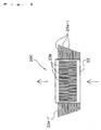
- a laser wavelength conversion apparatus 20B according to a third embodiment of the present invention will be described with reference to FIG. 4, a sectional side view, and FIG. 5, a view as viewed from the exit end surface side.
- a loop gas pipe 27 of a loop shape is disposed on the exit end surface side of a nonlinear optical crystal device 21.
- the loop gas pipe 27 is disposed in a state surrounding the exit end surface of the nonlinear optical crystal device 21, and a plurality of jet ports 27a are arranged at equal intervals on the inner periphery of the loop gas pipe 27.
- the loop gas pipe 27 is supplied with an inert gas G, such as helium or nitrogen.
- the inert gas is jetted evenly from the jet ports 27a toward the surroundings of the exit end surface of the nonlinear optical crystal device 21 to cool the exit end surface side of the nonlinear optical crystal device 21 evenly.
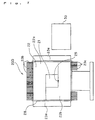
- a laser wavelength conversion apparatus 20C according to a fourth embodiment of the present invention will be described with reference to FIG. 6, a plan view.
- cooling fins 23a-1 provided on the right and left side surfaces of a heat sink 22 become longer from the entrance end surface side toward the exit end surface side. That is, the heat release ability on the exit end surface side is increased.
- the temperature gradient (temperature nonuniformity) along the direction of the optical axis of the nonlinear optical crystal device 21 can be eliminated to improve the conversion efficiency.
- a laser wavelength conversion apparatus 20D according to a fifth embodiment of the present invention will be described with reference to FIG. 7, a front view.
- a film-shaped heater 28 is employed as a heater for uniform heating, and no cartridge heater 24 is used.
- the film-shaped heater 28 is disposed in a state surrounding the outer peripheral surface of a heat sink 22, and its temperature is regulated by a heater controller 30.
- the configuration of other portions is the same as in the First Embodiment.
- the film-shaped heater 28 can uniformly raise the temperature of the heat sink 22, accordingly, nonlinear optical crystal device 21.
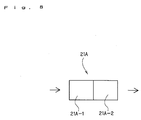
- the nonlinear optical crystal device 21A for use in a laser wavelength conversion apparatus according to a sixth embodiment of the present invention will be described with reference to FIG. 8.
- the nonlinear optical crystal device 21A is divided into two parts midway along the axial direction, and is constituted by connecting the resulting two nonlinear optical crystal devices 21A-1 and 21A-2.
- the temperature gradient temperature nonuniformity
- an anti-reflection coating for the incident laser light wavelength and the converted wavelength is applied to the entrance end surface and exit end surface of each of the nonlinear optical crystal devices 21A-1 and 21A-2, whereby losses can be decreased.
- the bonding end surfaces of the nonlinear optical crystal devices 21A-1 and 21A-2 are optically polished and bonded together, whereby reflection losses of incident laser light and converted light can be decreased.
- the nonlinear optical crystal device 21A can be divided into two or more parts.
- the laser wavelength conversion apparatus of the present invention when the repetition frequency of laser light is high, heating by the heater for uniform heating is stopped, whereby satisfactory cooling is performed by the heat sink having the cooling fins. As a result, the temperature of the wavelength conversion element can be brought to the set temperature at which the conversion efficiency is satisfactory.
- the repetition frequency of laser light is low, on the other hand, heating by the heater for uniform heating is carried out, whereby the temperature of the wavelength conversion element can be brought to the set temperature at which the conversion efficiency is satisfactory. Consequently, always satisfactory wavelength conversion can be achieved, even when the frequency of incident laser light is varied dynamically.
Landscapes
- Physics & Mathematics (AREA)
- Nonlinear Science (AREA)
- Chemical & Material Sciences (AREA)
- Crystallography & Structural Chemistry (AREA)
- General Physics & Mathematics (AREA)
- Optics & Photonics (AREA)
- Optical Modulation, Optical Deflection, Nonlinear Optics, Optical Demodulation, Optical Logic Elements (AREA)
Abstract
Description
Claims (9)
- A laser wavelength conversion apparatus comprising:a wavelength conversion element for performing wavelength conversion of laser light entered from an entrance end surface and delivering laser light of a shortened wavelength from an exit end surface;a heat sink surrounding a peripheral surface of said wavelength conversion element and having cooling fins;a heater for uniform heating disposed in said heat sink in such a state as to surround periphery of said wavelength conversion element;a temperature sensor for measuring a temperature of said wavelength conversion element; anda heater controller for controlling an electric current supplied to said heater for uniform heating so that the temperature detected by said temperature sensor becomes a preset temperature.
- A laser wavelength conversion apparatus as claimed in claim 1, characterized in that of the cooling fins of said heat sink, the cooling fins located on side surfaces are arranged in such a state as to extend in a vertical direction.
- A laser wavelength conversion apparatus as claimed in claim 1, characterized in that said heater for uniform heating is a plurality of rod-shaped heaters arranged in said heat sink at equal intervals in such a state as to surround the periphery of said wavelength conversion element and in such a state as to extend in a direction of an optical axis.
- A laser wavelength conversion apparatus as claimed in claim 1, characterized in that said heater for uniform heating is a film-shaped heater disposed in such a state as to surround an outer peripheral surface of said heat sink.
- A laser wavelength conversion apparatus as claimed in claim 1, characterized in thatheaters for temperature gradient correction are placed on an entrance side end surface and an exit side end surface of said heat sink, andsaid heater controller exercises temperature control such that an amount of heat generation from said heater for temperature gradient correction on an entrance end surface side is larger than an amount of heat generation from said heater for temperature gradient correction on an exit end surface side.
- A laser wavelength conversion apparatus as claimed in claim 1, characterized in that a loop gas pipe for blowing a cooling gas uniformly from surroundings toward the exit end surface of said wavelength conversion element is disposed on an exit end surface side of said heat sink.
- A laser wavelength conversion apparatus as claimed in claim 1, characterized in that said wavelength conversion element is divided along a direction of an optical axis.
- A laser wavelength conversion apparatus as claimed in claim 1, characterized in that said wavelength conversion element is divided along a direction of an optical axis, and an anti-reflection coating is applied to end surfaces of divisional wavelength conversion elements.
- A laser wavelength conversion apparatus as claimed in claim 1, characterized in that said wavelength conversion element is divided along a direction of an optical axis, and optical polishing is applied to end surfaces of divisional wavelength conversion elements.
Applications Claiming Priority (3)
| Application Number | Priority Date | Filing Date | Title |
|---|---|---|---|
| JP2000117635A JP3389197B2 (en) | 2000-04-19 | 2000-04-19 | Laser wavelength converter |
| JP2000117635 | 2000-04-19 | ||
| PCT/JP2001/003219 WO2001079929A1 (en) | 2000-04-19 | 2001-04-16 | Laser wavelength converter |
Publications (2)
| Publication Number | Publication Date |
|---|---|
| EP1189101A1 true EP1189101A1 (en) | 2002-03-20 |
| EP1189101A4 EP1189101A4 (en) | 2004-05-12 |
Family
ID=18628925
Family Applications (1)
| Application Number | Title | Priority Date | Filing Date |
|---|---|---|---|
| EP01921845A Withdrawn EP1189101A4 (en) | 2000-04-19 | 2001-04-16 | Laser wavelength converter |
Country Status (4)
| Country | Link |
|---|---|
| US (1) | US6744547B2 (en) |
| EP (1) | EP1189101A4 (en) |
| JP (1) | JP3389197B2 (en) |
| WO (1) | WO2001079929A1 (en) |
Cited By (1)
| Publication number | Priority date | Publication date | Assignee | Title |
|---|---|---|---|---|
| WO2015122854A3 (en) * | 2014-02-12 | 2015-10-15 | Optotek, D.O.O. | A mount for temperature stabilization of optical components |
Families Citing this family (22)
| Publication number | Priority date | Publication date | Assignee | Title |
|---|---|---|---|---|
| US6796710B2 (en) | 2001-06-08 | 2004-09-28 | Ethicon Endo-Surgery, Inc. | System and method of measuring and controlling temperature of optical fiber tip in a laser system |
| US6775315B1 (en) * | 2001-06-08 | 2004-08-10 | Scott Allen Nield | Apparatus and method of directing a laser beam to a thermally managed beam dump in a laser system |
| US7218653B2 (en) * | 2003-11-27 | 2007-05-15 | Mitsubishi Materials Corporation | Wavelength conversion method and wavelength conversion element |
| US20050257912A1 (en) * | 2004-01-12 | 2005-11-24 | Litelaser Llc | Laser cooling system and method |
| JP2005209679A (en) * | 2004-01-20 | 2005-08-04 | Japan Atom Energy Res Inst | Laser amplifier |
| JP4559758B2 (en) * | 2004-03-19 | 2010-10-13 | シチズンホールディングス株式会社 | Observation device |
| JP2005332989A (en) * | 2004-05-20 | 2005-12-02 | Topcon Corp | Laser oscillator |
| US20060098698A1 (en) * | 2004-11-10 | 2006-05-11 | Lightwave Electronics Corporation | Frequency-converting lasers with non-linear materials optimized for high power operation |
| US7570679B2 (en) * | 2006-02-22 | 2009-08-04 | Optical Communication Products, Inc. | Wide temperature range uncooled transceiver module for uncontrolled environments |
| US7113325B1 (en) | 2006-05-03 | 2006-09-26 | Mitsubishi Materials Corporation | Wavelength conversion method with improved conversion efficiency |
| US20090296756A1 (en) * | 2008-06-02 | 2009-12-03 | David Cullumber | Laser Frequency Multiplier with Temperature Control |
| JP2014089350A (en) * | 2012-10-30 | 2014-05-15 | Nippon Telegr & Teleph Corp <Ntt> | Mount for optical element |
| CN103794972B (en) * | 2014-02-26 | 2016-06-08 | 哈尔滨工业大学 | A kind of heavy caliber crystal high accuracy temperature control device |
| CN103794970B (en) * | 2014-02-26 | 2016-06-08 | 哈尔滨工业大学 | Heavy caliber crystal high accuracy temperature control device under a kind of vacuum condition |
| CN107615599B (en) * | 2015-05-12 | 2019-12-10 | 株式会社岛津制作所 | Passive Q-switched laser and its operation optimization method |
| ES3052382T3 (en) * | 2015-10-05 | 2026-01-07 | Ionq Inc | Tunable source bi-photons |
| DE102016202028B4 (en) | 2016-02-11 | 2017-12-07 | Trumpf Laser Gmbh | Holder for a wavelength conversion crystal and optical system with such a holder |
| US10153215B2 (en) * | 2016-08-04 | 2018-12-11 | Kla-Tencor Corporation | Oven enclosure for optical components with integrated purge gas pre-heater |
| CN107887781A (en) * | 2017-11-29 | 2018-04-06 | 山东航天电子技术研究所 | A kind of optical fiber output LD pumpings minimize medium module |
| US11204536B1 (en) * | 2020-12-17 | 2021-12-21 | Raytheon Company | Ultra-stable dual-mode operation optical crystal assembly for harmonic conversion |
| CN119731378A (en) * | 2022-07-21 | 2025-03-28 | Ipg光子公司 | Oven for nonlinear optical crystal and use method |
| CN118040435B (en) * | 2024-03-04 | 2024-11-05 | 齐鲁中科光物理与工程技术研究院 | Quick stable temperature control device for frequency doubling crystal |
Family Cites Families (15)
| Publication number | Priority date | Publication date | Assignee | Title |
|---|---|---|---|---|
| US4820011A (en) * | 1986-07-07 | 1989-04-11 | Fuji Photo Film Co., Ltd. | Optical wavelength conversion device, and a method of making the same |
| US5315433A (en) * | 1991-02-28 | 1994-05-24 | Fuji Photo Film Co., Ltd. | Optical wavelength converting apparatus |
| JPH0572577A (en) | 1991-09-11 | 1993-03-26 | Hitachi Ltd | Non-linear optical crystal holder |
| JPH05100267A (en) | 1991-10-04 | 1993-04-23 | Matsushita Electric Ind Co Ltd | Optical higher harmonics generation device |
| US5353292A (en) * | 1991-10-31 | 1994-10-04 | Hoya Corporation | Laser light wavelength conversion apparatus capable of providing a uniform temperature distribution |
| JPH05218530A (en) * | 1992-01-31 | 1993-08-27 | Hoya Corp | Holding device for optical component of laser and solid state laser device |
| JPH06289446A (en) | 1993-04-05 | 1994-10-18 | Idemitsu Kosan Co Ltd | Optical higher harmonic generator |
| JPH07306428A (en) | 1994-05-07 | 1995-11-21 | Samsung Electron Co Ltd | Second harmonic generator |
| US5754714A (en) * | 1994-09-17 | 1998-05-19 | Kabushiki Kaisha Toshiba | Semiconductor optical waveguide device, optical control type optical switch, and wavelength conversion device |
| JPH0895104A (en) | 1994-09-26 | 1996-04-12 | Agency Of Ind Science & Technol | Laser resonator |
| US5935467A (en) * | 1997-05-14 | 1999-08-10 | General Electric Company | Oven for heating a crystal for a laser frequency conversion |
| JPH1164903A (en) | 1997-08-22 | 1999-03-05 | Sony Corp | Wavelength conversion element and method of using the same |
| US6069792A (en) * | 1997-09-16 | 2000-05-30 | Nelik; Jacob | Computer component cooling assembly |
| JPH11119272A (en) | 1997-10-17 | 1999-04-30 | Hyper Photon System:Kk | Laser system |
| US6374906B1 (en) * | 2000-04-11 | 2002-04-23 | Hewlett-Packard Company | Heat sink having a captive handle |
-
2000
- 2000-04-19 JP JP2000117635A patent/JP3389197B2/en not_active Expired - Fee Related
-
2001
- 2001-04-16 WO PCT/JP2001/003219 patent/WO2001079929A1/en not_active Ceased
- 2001-04-16 EP EP01921845A patent/EP1189101A4/en not_active Withdrawn
- 2001-04-16 US US09/926,785 patent/US6744547B2/en not_active Expired - Fee Related
Cited By (1)
| Publication number | Priority date | Publication date | Assignee | Title |
|---|---|---|---|---|
| WO2015122854A3 (en) * | 2014-02-12 | 2015-10-15 | Optotek, D.O.O. | A mount for temperature stabilization of optical components |
Also Published As
| Publication number | Publication date |
|---|---|
| US20020136247A1 (en) | 2002-09-26 |
| JP2001305592A (en) | 2001-10-31 |
| US6744547B2 (en) | 2004-06-01 |
| EP1189101A4 (en) | 2004-05-12 |
| JP3389197B2 (en) | 2003-03-24 |
| WO2001079929A1 (en) | 2001-10-25 |
Similar Documents
| Publication | Publication Date | Title |
|---|---|---|
| US6744547B2 (en) | Laser wavelength converter | |
| TW517313B (en) | Windows used in thermal processing chambers | |
| US5898718A (en) | Method and apparatus for optimizing the output of a multi-peaked frequency harmonic generator | |
| US9963800B2 (en) | Method of making a sapphire component including machining a sapphire single crystal | |
| KR100634642B1 (en) | Rapid heating and cooling device for semiconductor wafer | |
| JP7085895B2 (en) | Methods and devices for controlling the thickness of strips | |
| JP2007298933A (en) | Wavelength conversion method | |
| KR101963611B1 (en) | Apparatus and method for growing silicon crystal substrate | |
| US5867303A (en) | Method and apparatus for optimizing the output of a harmonic generator | |
| JPH08339002A (en) | Second harmonic wave generating element and its production | |
| JP5127532B2 (en) | Wafer heat treatment system | |
| CN106133208B (en) | Apparatus for controlling heat flow in a melt and method of processing the same | |
| JP2004111765A (en) | Narrow-band laser device | |
| JP4568003B2 (en) | Optical fiber manufacturing method and manufacturing apparatus | |
| KR102155100B1 (en) | Electrode tip for arc lamp | |
| JP2763187B2 (en) | Solid-state laser device | |
| Jundt et al. | Growth and optical properties of single-crystal sapphire fibers | |
| US20260044047A1 (en) | Adapting optical properties of a continuous body comprising nonlinear optical material to light of different wavelengths by adjusting a temperature distribution in the continuous body | |
| Chaplygin et al. | Heat Transfer and Behavior of Silicon Carbide in Subsonic Nitrogen and Carbon Dioxide Plasma Flows under Additional Radiative Heating | |
| Chen et al. | Growth and laser performance of slab Ti: sapphire crystals by Rectangular crucible Czochralski method | |
| Huang et al. | Stabilizing High-Energy Solid-State Laser Conversion with Precision Temperature Control | |
| Al-Chalabi | Transient annealing of planar waveguides formed by 4He+ ion implantation into LiNbO3 | |
| Bera et al. | Growth of rare-earth doped single crystal yttrium aluminum garnet fibers | |
| JP3630508B2 (en) | Dye laser device | |
| JPS5933555B2 (en) | Single crystal growth method and apparatus |
Legal Events
| Date | Code | Title | Description |
|---|---|---|---|
| PUAI | Public reference made under article 153(3) epc to a published international application that has entered the european phase |
Free format text: ORIGINAL CODE: 0009012 |
|
| 17P | Request for examination filed |
Effective date: 20011204 |
|
| AK | Designated contracting states |
Kind code of ref document: A1 Designated state(s): AT BE CH CY DE DK ES FI FR GB GR IE IT LI LU MC NL PT SE TR |
|
| A4 | Supplementary search report drawn up and despatched |
Effective date: 20040325 |
|
| RIC1 | Information provided on ipc code assigned before grant |
Ipc: 7G 02F 1/35 B Ipc: 7G 02F 1/37 A |
|
| 17Q | First examination report despatched |
Effective date: 20040414 |
|
| RBV | Designated contracting states (corrected) |
Designated state(s): DE FR GB |
|
| 17Q | First examination report despatched |
Effective date: 20040414 |
|
| STAA | Information on the status of an ep patent application or granted ep patent |
Free format text: STATUS: THE APPLICATION IS DEEMED TO BE WITHDRAWN |
|
| 18D | Application deemed to be withdrawn |
Effective date: 20061121 |