TECHNICAL FIELD
The present invention relates to an air conditioning
apparatus for conditioning air such as an air conditioner.
BACKGROUND ART
For example, an air conditioning apparatus of the type
installed on a ceiling is known. The air conditioning
apparatus of this type includes a main body located in a
ceiling, and a decorative panel located on the lower face of
the main body to give on a room. This decorative panel has
an approximately square shape when viewed at the bottom face,
provided roughly in the center of the bottom face is a
rectangular inlet through which room air is taken into the
main body, and provided around the inlet are a plurality of,
e.g., four, elongated outlets. Each of these outlets is
formed into an elongated shape along the corresponding side
of the inlet.
Now, depending on the installation location of an air
conditioning apparatus, there is a need to allow the quantity
of air discharge to differ from outlet to outlet. As an air
conditioning apparatus that can satisfy such a need, an air
conditioning apparatus in which the width of an air passage
in each outlet is made variable to adjust the quantity of air
discharge is known (see Japanese Unexamined Patent
Publication NO. 2-8648, for example).
In this air conditioning apparatus, the quantity of air
discharge is adjusted by narrowing or expanding the width of
each outlet (i.e., its dimension along the longitudinal
direction) with a baffle plate that can be displaced in the
longitudinal direction of the outlet.
-SOLUTION-
However, if the width of each outlet is narrowed in the
longitudinal direction, the width of discharged air flow is
also narrowed, thereby reducing the space to be air-conditioned.
This results in making it hard for the
discharged air flow to sufficiently reach every corner of a
room, and the comfortableness and the efficiency of air
conditioning might be thus impaired.
It is therefore the object of the present invention to
provide an air conditioning apparatus which can solve the
above-described technical problem, can adjust the quantity of
air discharge from each outlet and can also maintain the
width of discharged air flow by the adjustment.
DISCLOSURE OF INVENTION
A first invention is directed to an air conditioning
apparatus including an elongated outlet and provides the air
conditioning apparatus that further includes air passage
dimension adjustment means for adjusting an air passage
dimension of the outlet in a transverse direction thereof.
According to this invention, the quantity of air
discharge can be restricted, for example, by narrowing the
air passage dimension in the transverse direction of the
outlet. In this case, since the air passage dimension in the
longitudinal direction of the outlet can be maintained in the
same way as in the case where the quantity of air discharge
is not restricted, the width of discharged air flow (i.e.,
the dimension of the outlet along the longitudinal direction)
can be widely maintained. As a result, a wide space can be
air-conditioned.
A second invention is directed to the air conditioning
apparatus based on the first invention and provides one
wherein the air passage dimension adjustment means includes a
baffle plate that extends in the longitudinal direction of
the outlet and that is rotated with respect to an axis
extending in the longitudinal direction.
According to this invention, the quantity of air
discharge can be adjusted, in a simple structure in which the
rotatable baffle plate is used, without narrowing the width
of discharged air flow. Furthermore, the rotatable baffle
plate can adjust the air passage dimension as desired in a
small space of the outlet in which the baffle plate is
placed.
A third invention is directed to the air conditioning
apparatus based on the second invention and provides one
wherein the baffle plate is formed with a large number of
small holes for ventilation.
According to this invention, the quantity of air
discharge when the air passage dimension is narrowed to its
maximum can be precisely restricted.
Also, an air deflection plate for guiding the discharged
air flow may be provided in the outlet on the downstream side
of the baffle plate. If the above-described small holes are
provided in such a case, air streams flowing along the air
deflection plate can be increased, thereby surely obtaining
the effect of adjusting the direction of air by the air
deflection plate.
A fourth invention is directed to the air conditioning
apparatus based on the second or third invention and provides
one wherein the baffle plate includes first and second plates
that are relatively rotatably connected at adjacent edges
thereof.
According to this invention, the plates are both
relatively rotated to change the baffle plate into a folded
state, thereby realizing adjustment to a desired air passage
dimension in a small space.
A fifth invention is directed to the air conditioning
apparatus based on the fourth invention and provides one
wherein the air passage dimension adjustment means includes:
a connection for rotatably connecting the adjacent edges of
the first and second plates; a fixed part; and a movable
part, the fixed and movable parts being provided to extend
along the other edges of the first and second plates,
respectively, wherein the movable part is actuated along a
guide groove extending along the transverse direction of the
outlet with the fixed part fixed, thereby allowing the
connection to move correspondingly.
According to this invention, by a simple operation of
moving the movable part along the guide groove, both the
plates are moved conjunctly to adjust the air passage
dimension with the baffle plate.
A sixth invention is directed to the air conditioning
apparatus based on the fourth invention and provides one
wherein the air passage dimension adjustment means includes:
a first shaft for rotatably connecting the adjacent edges of
the first and second plates; and second and third shafts
provided to extend along the other edges of the first and
second plates, respectively, wherein either one of the second
and third shafts is fixed, and the other is actuated along
the transverse direction of the outlet.
According to this invention, since the transverse
direction, which is also the direction to operate the baffle
plate, coincides with the direction to adjust the air passage
dimension, the adjustment operation can easily be understood.
A seventh invention is directed to the air conditioning
apparatus based on the fourth invention and provides one
wherein the air passage dimension adjustment means includes:
a first shaft for. rotatably connecting the adjacent edges of
the first and second plates; second and third shafts provided
to extend along the other edges of the first and second
plates, respectively; a vertical groove for guiding vertical
motions of the first shaft; horizontal grooves for guiding
motions of the second and third shafts in the transverse
direction of the outlet, respectively; and an actuating
mechanism for actuating either one of the shafts along the
groove that guides this shaft.
According to this invention, since the shafts are each
guided along the corresponding groove, the air passage
dimension can be equally adjusted with the baffle plate even
by actuating any shaft. Therefore, it is possible to
increase the degree of freedom of the shaft to be actuated
and the layout flexibility of the actuating mechanism.
An eighth invention is directed to the air conditioning
apparatus based on the seventh invention and provides one
wherein the actuating mechanism includes a screw-operated
actuating mechanism.
According to this invention, the actuating mechanism not
only can have a simplified structure but also can be reduced
in size.
A ninth invention is directed to the air conditioning
apparatus based on the eighth invention and provides one
wherein the screw-operated actuating mechanism includes: a
bolt that is rotationally actuated with movement thereof in
an axial direction restricted; and a non-rotatable nut that
engages the bolt and moves together with the actuated shaft.
According to this invention, the actuating mechanism can
have a further simplified structure and can be further
reduced is size.
A tenth invention is directed to the air conditioning
apparatus based on the first invention and provides one
wherein the air passage dimension adjustment means includes a
baffle member that extends in the longitudinal direction of
the outlet and that moves in parallel with a plane of an
opening of the outlet and in the transverse direction of the
outlet.
According to this invention, the quantity of air
discharge can be adjusted, in a simple structure in which the
baffle member movable in the plane is used, without narrowing
the width of discharged air flow.
An eleventh invention is directed to the air
conditioning apparatus based on the first invention and
provides one wherein the air passage dimension adjustment
means includes one or more plate-like baffle members that are
detachably attached to the outlet and that are formed to
extend in the longitudinal direction of the outlet and to
have a width smaller than the dimension in the transverse
direction of the outlet.
According to this invention, the guantity of air
discharge can be adjusted, in a simple structure in which the
detachable baffle member is used, without narrowing the width
of discharged air flow. Furthermore, since the baffle member
can be detached, adjustment can be made to a desired air
passage dimension without the need for any space for
containing the baffle member.
A twelfth invention is directed to the air conditioning
apparatus based on the first invention and provides one that
includes: a decorative panel that is provided with a
plurality of the outlets and is located on a ceiling; and an
apparatus main body which is located above the decorative
panel to discharge conditioned air out of the outlets.
The air passage dimension adjustment means according to
the present invention is preferably applied to an air
conditioning apparatus of the type embedded within a ceiling,
i.e., a so-called "cassette type" air conditioning apparatus.
BRIEF DESCRIPTION OF DRAWINGS
FIG. 1 is a front cross-sectional view of a general
structure of an air conditioning apparatus for illustrating a
first embodiment of the present invention.
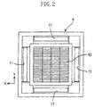
FIG. 2 is a bottom view of a decorative panel of the air
conditioning apparatus shown in FIG. 1.
FIG. 3 illustrates in bottom view the operation of an
air passage dimension adjustment mechanism in an outlet of
the air conditioning apparatus shown in FIG. 1, in which an
air deflection plate is omitted, and (a) through (c) show
respective states of the present invention in order of
increasing the air passage dimension, while (d) shows a state
of an outlet in an comparative example where the air passage
dimension is approximately half-closed.
FIG. 4 is a front cross-sectional view of the air
passage dimension adjustment mechanism shown in FIG. 3, and
shows that a baffle plate is opened.
FIG. 5 is a front cross-sectional view of the air
passage dimension adjustment mechanism shown in FIG. 3, and
shows that the baffle plate is approximately half-opened.
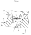
FIG. 6 is a front cross-sectional view of the air
passage dimension adjustment mechanism shown in FIG. 3, and
shows that the baffle plate is closed.
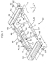
FIG. 7 is an exploded perspective view of the air
passage dimension adjustment mechanism shown in FIG. 3.
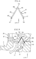
FIG. 8 is a front cross-sectional view of a modification
of a connection of the baffle plate of the air passage
dimension adjustment mechanism shown in FIG. 3.
FIG. 9 is a front cross-sectional view of an air passage
dimension adjustment mechanism of an air conditioning
apparatus for illustrating a second embodiment of the present
invention, and shows that a baffle plate is closed.
FIG. 10 is a front cross-sectional view of an air
passage dimension adjustment mechanism of an air conditioning
apparatus for illustrating a third embodiment of the present
invention, and shows that a baffle plate is opened.
FIG. 11 is a front cross-sectional view of the air
passage dimension adjustment mechanism shown in FIG. 10, and
shows that the baffle plate is closed.
FIG. 12 is a lateral cross-sectional view of the air
passage dimension adjustment mechanism shown in FIG. 10.
FIG. 13 is an exploded perspective view of the air
passage dimension adjustment mechanism shown in FIG. 10.
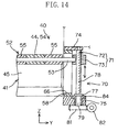
FIG. 14 is a lateral cross-sectional view which shows a
modification of an air passage dimension adjustment mechanism
of an air conditioning apparatus for illustrating a fourth
embodiment of the present invention.
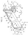
FIG. 15 is a perspective view of the air passage
dimension adjustment mechanism shown in FIG. 14.
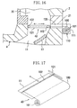
FIG. 16 is a cross-sectional view of an air passage
dimension adjustment mechanism for illustrating a fifth
embodiment of the present invention.
FIG. 17 is a perspective view of the air passage
dimension adjustment mechanism for illustrating the fifth
embodiment of the present invention.
FIG. 18 is a cross-sectional view of an air passage
dimension adjustment mechanism for illustrating a sixth
embodiment of the present invention.
FIG. 19 is a perspective view of the air passage
dimension adjustment mechanism for illustrating the sixth
embodiment of the present invention.
BEST MODE FOR CARRYING OUT THE INVENTION
An air conditioning apparatus according to a first
embodiment of the present invention will be described with
reference to the accompanying drawings. FIG. 1 is a front
cross-sectional view of a general structure of the above-described
air conditioning apparatus.
The air conditioning apparatus 1 is of the type embedded
within a ceiling and includes an air conditioning apparatus
main body 2 (which will be hereinafter called an "apparatus
main body") located within the ceiling and a decorative panel
4 attached to a lower face 3 of this apparatus main body 2.
The decorative panel 4 is located along a ceiling surface 5
to give on a room.
As shown in the bottom view of FIG. 2, the decorative
panel 4 is formed into an approximately rectangular shape in
plan view and includes an approximately rectangular inlet 10
in the center thereof and a plurality of, e.g., four, outlets
11 surrounding this inlet 10. Each of the outlets 11 is an
elongated one which extends in the direction along the
corresponding side of the rectangular shape of the inlet 10
and is formed into a rectangle on the surface of the
decorative panel 4. As shown in FIG. 1, each of the outlets
11 is provided with an air deflection plate 13 for guiding
discharged air flow in a predetermined direction. In
addition, located above the inlet 10 is a filter 12 through
which dust is removed.
Inside of the apparatus main body 2 is defined an air
passage 20. This air passage 20 is in communication with the
inlet 10 and each outlet 11. The apparatus main body 2
includes a casing 21 formed into a box-like shape, a
centrifugal blower 22 located in the center of this casing 21,
and a finned coil heat exchanger 25 located annularly to
surround this centrifugal blower 22. The blower 22 is made
up of a turbofan 23 and a fan motor 24 for rotatively driving
this turbofan 23 in a predetermined rotational direction.
The turbofan 23 rotates about the central axis of rotation
which extends along the vertical direction.
Further, the apparatus main body 2 is provided with: a
heat insulator 26, disposed along the inner face of the
casing 21, for thermally insulating the air passage 20 from
the exterior of the casing 21; an annular drain pan 27,
placed below the heat exchanger 25, for receiving water drops
falling from the heat exchanger 25; a bell mouth 28, placed
inside from the drain pan 27, for directing air from the
inlet 10 toward the turbofan 23; and an electrical equipment
box 29, disposed on the lower face of the bell mouth 28, for
containing electrical equipment such as a circuit board.
The air passage 20 includes: a first section, located in
the center of the casing 21, in which air flows upwardly from
the inlet 10 into the turbofan 23; a second section in which
air flows, by means of the turbofan 23, almost horizontally
and radially outwardly of the turbofan 23 and passes through
the heat exchanger 25; and a third section in which air flows
downwardly along the lateral face of the casing 21 to reach
each outlet 11.
On activation of the fan motor 24, air is sucked through
the inlet 10, passes through the first and second sections of
the air passage 20, and then undergoes heat exchange at the
heat exchanger 25. The air is heated up during heating
operation while it is cooled down during cooling operation.
Next, the air passes through the third section of the air
passage 20 and is then discharged from the four outlets 11
toward the room.
The air conditioning apparatus 1 according to the
present invention includes an air passage dimension
adjustment mechanism 40 for adjusting the air passage
dimension (W1) at each outlet 11 which extends along the
transverse direction of each outlet 11. In this structure,
as shown in FIG. 3, the quantity of air discharge from each
outlet 11 can be adjusted without changing the width of
discharged air flow from each outlet 11 (i.e., the dimension
of each outlet 11 in the longitudinal direction).
FIGS. 4 through 6 are front cross-sectional views, each
showing the air passage dimension adjustment mechanism 40 and
the region adjacent thereto (the region A in FIG. 1). FIG. 4
shows the state in which the outlet 11 is open, FIG. 5 shows
the state in which the outlet 11 is half-open, and FIG. 6
shows the state in which the outlet 11 is closed. FIG. 7 is
an exploded perspective view of the air passage dimension
adjustment mechanism 40.
As shown in FIG. 7, the air passage dimension adjustment
mechanism 40 includes: a baffle plate 41, which is provided
in the outlet 11 in a displaceable manner, for baffling, such
as stemming or restricting, air flow in the outlet 11 through
its displacement; a displacement mechanism 42 for supporting
the baffle plate 41 to allow the displacement of the baffle
plate 41 and for guiding the baffle plate 41 to a
predetermined position; and a holding mechanism 43 for
holding the position of the baffle plate 41. The respective
members of the air passage dimension adjustment mechanism 40
are placed on the upper face side of the decorative panel 4.
The air passage dimension adjustment mechanism 40 is provided
in each outlet 11.
Each outlet 11 is defined by a member, which is provided
in the decorative panel 4, for forming an air passage. Each
outlet 11 includes an exit facing the room and an outlet air
passage that adjoins this exit at the upstream side, with the
upstream side region of this outlet air passage being in
communication with the lowermost downstream region of the
third section of the air passage. 20 of the apparatus main
body 2. The exit is formed into a rectangle. The outlet air
passage has a rectangular cross section substantially equal
in shape to the exit and extends in the vertical direction,
thus allowing air to flow vertically. The rectangular cross
section of the outlet air passage coincides longitudinally
with the rectangle of the exit. The outlet air passage
includes an air deflection plate 13 disposed in the vicinity
of the exit, and the baffle plate 41 is disposed in a region
of the outlet air passage immediately upstream of the air
deflection plate 13.
In the description below, the direction in which the
outlet 11 is longer, i.e., its lengthwise direction, will be
called a "longitudinal direction", while the direction in
which the outlet 11 is shorter, i.e., its widthwise direction,
will be called a "transverse direction". Also, in each of
the drawings, shown as needed are the arrow Y indicating the
longitudinal direction, the arrow X indicating the transverse
direction, and the arrow Z indicating the vertical direction.
The baffle plate 41 includes a first plate 44 and a
second plate 45 that are relatively rotatably connected at
adjacent edges 46 and 49 thereof. The plates 44 and 45 have
substantially the same shape and are each formed into a long,
approximately rectangular shape along the longitudinal
direction of the outlet 11. The corresponding long sides of
this rectangle include the above-described edges 46 and 49,
respectively, and are nearly equal to those of the cross
sectional shape of the outlet air passage. Further, the
short side of the rectangle is nearly half of that of the
cross sectional shape of the outlet air passage.
Furthermore, the baffle plate 41 is provided with a
connection 52 which includes a first shaft 53 for rotatably
connecting the first plate 44 and the second plate 45 at
their adjacent edges 46 and 49, and a second shaft 56 and a
third shaft 57 that are provided to extend along the other
edges 47 and 50 of the plates 44 and 45, respectively. The
second shaft 56 and the third shaft 57 extend longitudinally,
in parallel with each other, from transverse edges 48 and 51
of the plates 44 and 45, respectively.
The baffle plate 41 can be folded up by relatively
rotating both the plates 44 and 45 with respect to the axis
of the first shaft 53. In this manner, the baffle plate 41
can be in a flat state in which both the plates 44 and 45 are
positioned to extend opposite to each other from the first
shaft 53 (see FIG. 6), a superposed state in which both the
plates 44 and 45 are positioned to extend in the same
direction from the first shaft 53 (see FIG. 4), and a half-folded
state in which both the plates 44 and 45 are
positioned in a half-folded manner (see FIG. 5).
The baffle plate 41 extends in the longitudinal
direction of the outlet 11 in each of the states described
above and is rotationally displaced relative to the axis C of
the second shaft 56. By rotationally displacing the baffle
plate 41, the edge 50 of the baffle plate 41 moves back and
forth in the outlet air passage along the transverse
direction. As a result, the dimension of the baffle plate 41
measured along the transverse direction can be changed, while
the air passage dimension can be adjusted transversely
between the inner face of the air passage and the edge 50.
Furthermore, when the baffle plate 41 is folded up by
relatively rotating both the plates 44 and 45 with respect to
the first shaft 53 so that the dimension of the baffle plate
41 measured along the transverse direction is reduced, the
dimension of the baffle plate 41 measured along the flowing
direction of air can also be reduced.
The baffle plate 41 can be displaced to assume an opened
position for expanding the air passage dimension (see FIG. 4),
a closed position for narrowing the air passage by the
rotation from the opened position with respect to the second
shaft 56 (see FIG. 6), and an arbitrarily half-opened
position located between the opened position and closed
position (see FIG. 5). The baffle plate 41 can be guided by
the displacement mechanism 42 to smoothly realize each of the
positions and states described above.
The displacement mechanism 42 includes: the abovedescribed
connection 52; the second shaft 56 as a fixed part
to be fixed, the third shaft 57 as a movable part to be
actuated; a pair of bearings 59 for rotatably supporting the
second shaft 56 while restricting its position; and guide
members 58 for guiding the third shaft 57. Each of these
guide members 58 is formed with a guide groove 60 extending
along the transverse direction. Also, the edge 50 of the
second plate 45, on which the third shaft 57 is located, is
formed with a pinchable operating knob 61 for facilitating
the actuation of the third shaft 57 by manual operation.
The connection 52 includes a plurality of tubes 54
provided on the first plate 44, a plurality of tubes 55
provided on the second plate 45, and the above-described
first shaft 53 passing through the tubes 54 and 55 of both
the plates 44 and 45, thus forming a hinge for rotatably
supporting both the plates 44 and 45 with respect to the
first shaft 53.
The guide members 58 and bearings 59 are provided
correspondingly to make a pair on both sides with respect to
the longitudinal direction of the outlet 11 and are fixed to
the decorative panel 4. Each of the bearings 59 is located
beside an end of the corresponding guide groove 60 which is
located closer to the inlet 10. The guide grooves 60 are open
to the outlet air passage. Fitted into the guide grooves 60
are the second shaft 56 as the fixed part and the third shaft
57 as the movable part. The second shaft 56 is supported,
with passing through the guide grooves 60, by the bearings 59.
Both the shafts 56 and 57 that have been fitted into the same
guide grooves 60 in this manner are brought closer to each
other in the opened position of the baffle plate 41 so that
they can be compactly positioned.
The holding mechanism 43 is made up of a pair of sealing
members 62, each applied to a part of the corresponding guide
member 58 which forms an inner face of the air passage, and
the edges 48 and 51 of the first plate 44 and the second
plate 45 which face the sealing members 62. Each of the
sealing members 62 is formed into a plate of elastic material
and is in contact with the corresponding edges 48 and 51 of
the baffle plate 41. When the baffle plate 41 is in the
closed position, each sealing member 62 is in contact with
almost the entire surfaces of the edges 48 and 51 which face
the sealing member 62. When the baffle plate 41 is in the
half-opened position, each sealing member 62 is at least
partially in contact with the edges 48 and 51 to cause
frictional resistance, thereby holding the position of the
baffle plate 41.
The adjustment of the air passage dimension is carried
out as follows. Specifically, the operating knob 61 is
manipulated with fingers or a tool through the outlet 11 to
actuate and displace the third shaft 57 as the movable part
along the guide groove 60. This movement, with the second
shaft 56 positionally restricted, allows the connection 52 to
correspondingly move through the second plate 45 and allows
the second plate 45 to rotate on the second shaft 56 while
relatively rotating both the plates 44 and 45. Thus, the
baffle plate 41 can be displaced to assume a desired position.
In the closed position, as shown in FIG. 6, the baffle
plate 41 is in the flat state so that the direction in which
both the plates 44 and 45 are aligned is approximately
perpendicular to the flow direction in the outlet air passage.
The baffle plate 41 reduces the air passage dimension of the
outlet air passage to zero to fully close the outlet 11 and
thereby also reduce the quantity of air discharge to zero.
In this state, the baffle plate 41 is positioned to rise at
the center thereof, thus steadily receiving wind pressure
applied upon the baffle plate 41.
If the first plate 44 is rotated with respect to the
second shaft 56 from the closed state, the baffle plate 41 is
allowed to assume the half-opened position, and if the first
plate 44 is further rotated by approximately 90 degrees and
erected, the baffle plate 41 is allowed to assume the opened
position. The baffle plate 41 in the opened and half-opened
positions is located right above the air deflection plate 13
in the outlet air passage. In these cases, when viewed in a
cross-section taken across the longitudinal direction, the
baffle plate 41 is located at the side of the outlet air
passage where the air deflection plate 13 is placed with
respect to the line which extends along the flow direction
and which goes through the transverse center of the outlet
air passage (see the line CL shown in FIG. 5), so that the
baffle plate 41 opens the space of the outlet air passage
located at the opposite side thereof.
In the opened position, as shown in FIG. 4, the baffle
plate 41 is in the superposed state in which both the plates
44 and 45 are folded up and opposed face to face so that they
are superposed along the direction of air flow. In the
opened position, the baffle plate 41 expands the air passage
dimension to its maximum to fully open the outlet 11. As a
result, the quantity of air discharge also reaches its
maximum. In this case, since both the plates 44 and 45 can
be positioned along the flowing direction of air through
their superposition, this prevents the baffle plate 41 from
baffling air flow.
In the half-opened position, as shown in FIG. 5, the
baffle plate 41 assumes such a V-shaped attitude that both
the plates 44 and 45 deploy toward the downstream side. In
this attitude, the top of the folded portion of the baffle
plate 41 faces the upstream side. The baffle plate 41
partially opens the outlet 11 with transverse air passage
dimension W1 set at a desired value in the range from zero to
a value corresponding to the opened position. Accordingly,
the quantity of air discharge can be adjusted in accordance
with the transverse air passage dimension W1.
It should be noted that, although the baffle plate 41
can completely close the outlet 11 in this embodiment, the
present invention is not limited to this arrangement. For
example, in the case where it will be sufficient if the
quantity of air discharge from the outlet 11 is made
adjustable within a predetermined range exceeding zero, a gap
for ventilation may be secured between each of the edges 47
and 50 of the baffle plate 41 and the inner face of the air
passage when the baffle plate 41 is in the closed position.
Alternatively, ventilation may also be carried out as in a
second embodiment.
Next, the second embodiment will be described.
The second embodiment differs from the first embodiment
in the points described below and is constituted in a manner
similar to the first embodiment as for the other points;
therefore, the same members are identified by the same
reference characters and the description thereof will be
omitted. FIG. 9 is a front cross-sectional view of a region
adjacent to the outlet 11 in this embodiment.
The baffle plate 41 in the second embodiment is formed
with a large number of small holes 65 for ventilation. The
small holes 65 are dispersedly arranged over almost the
entire surfaces of the first plate 44 and the second plate 45.
Via these small holes 65, ventilation is allowed through the
baffle plate 41.
Next, a third embodiment will be described.
The third embodiment differs from the first embodiment
in the points described below and is constituted in a manner
similar to the first embodiment as for the other points;
therefore, the same members are identified by the same
reference characters and the description thereof will be
omitted.
In the third embodiment, as shown in FIG. 13, the
displacement mechanism 42 differs from that in the first
embodiment. The second shaft 56 can also be displaced.
The displacement mechanism 42 includes: the above-described
first shaft 53 for rotatably connecting the first
plate 44 and the second plate 45 at their adjacent edges 46
and 49; the second shaft 56 and the third shaft 57 that are
provided to extend along the other edges 47 and 50 of the
first plate 44 and the second plate 45, respectively; and a
pair of guide members 58 for guiding the first through third
shafts 53, 56, and 57. The pair of guide members 58 are
opposed to each other and disposed correspondingly at the
ends of the baffle plate 41 in the longitudinal direction.
Each of the guide members 58 is provided with a vertical
groove 66 for guiding vertical motions of the first shaft 53,
and a pair of horizontal grooves 67 and 68 for guiding
transverse motions of the second shaft 56 and the third shaft
57, respectively. In addition, the displacement mechanism
42 includes an actuating mechanism 70 for actuating the first
shaft 53 along the vertical groove 66.
As shown in FIG. 10 and FIG. 11, when viewed in a cross
section taken across the longitudinal direction, the vertical
groove 66 is located at a position roughly corresponding to
the center of the outlet air passage in the transverse
direction and extends vertically. The pair of horizontal
grooves 67 and 68 are aligned in the transverse direction and
arranged on both sides of the vertical groove 66,
respectively. The vertical groove 66 and the pair of
horizontal grooves 67 and 68 are separated from one another.
The pair of horizontal grooves 67 and 68 are on substantially
the same level with the lower end of the vertical groove 66
and each extend horizontally in such a manner as to get away
from the vicinity of the vertical groove 66. The ends of the
pair of horizontal grooves 67 and 68 away from each other are
formed to cut into inner walls of the outlet air passage.
In the baffle plate 41 in the closed position, both the
plates 44 and 45 are aligned so that the upper faces thereof
are substantially flush with each other, while the remote
edges 47 and 50 of both the plates 44 and 45 enter the
portions of the grooves formed in the inner walls of the air
passage. Also, in the opened position, the baffle plate 41
is located roughly in the transverse center of the outlet air
passage and takes the shape of a roughly inverted V. Further,
in the baffle plate 41 in the half-opened position, the angle
formed in a V shape by both the plates is larger than that
formed by both the plates in the opened position.
Furthermore, the air passage dimension can be adjusted
transversely between a pair of transversely opposed inner
surfaces of the air passage and both the edges 47 and 50 of
the baffle plate 41, in which case air flows on both sides of
the baffle plate 41 in the transverse direction.
As shown in FIG. 12, the actuating mechanism 70 includes
a screw-operated actuating mechanism 71. This screw-operated
actuating mechanism 71 includes: a bolt 72 that is
rotationally movable with its axial movement restricted; and
a nut 73 engaged with the bolt 72 in a manner that its female
thread is screwed on a male thread of the bolt 72. This nut
73 is fitted fixedly to the first shaft 53 to be actuated and
is relatively rotatable with the bolt 72 but not rotatable
around the central axis of the bolt 72. In accordance with
the rotational movement of the bolt 72, the nut 73 and the
first shaft 53 move together.
The bolt 72 includes a screwed portion 78 that is
externally threaded and extends in one direction (i.e., the
axial direction), a joint 79 that is provided at the end of
this screwed portion 78 and has a circumferential face, and a
head 76 provided at the end of the joint 79.
The screwed portion 78 is placed to be in parallel with
the vertical groove 66 for guiding the first shaft 53 and to
extend in the vertical direction. The bolt 72 is rotatably
supported by a supporting member 74 disposed on the upper end
of the screwed portion 78 and a supporting member 75 provided
around the joint 79. Also, the supporting member 75 is
sandwiched between a snap ring 77 and the head 76 that are
fitted to the joint 79. Thus, the bolt 72 is restrained
against axial movement. The head 76 of the bolt 72 is placed
downwardly and is easily operable from beneath with the use
of a tool T such as a screwdriver.
On rotation of the bolt 72, the nut 73 and the first
shaft 53 move along the vertical groove 66. In parallel with
this, the second shaft 56 and the third shaft 57 move along
the corresponding horizontal grooves 67 and 68, thereby
smoothly displacing the baffle plate 41. For example, if the
bolt 72 is moved to rotate right-handedly, the nut 73 moves
downward and the first shaft 53 also moves in the same way.
Correspondingly, the baffle plate 41 is displaced to the
closed position. If the bolt 72 is rotated reversely, the
nut 73 and the first shaft 53 move upward, and the baffle
plate 41 is thus displaced toward the opened position.
In the third embodiment, the actuating mechanism 70 for.
actuating the first shaft 53 is provided, but the present
invention is not limited to this. For example, the actuating
mechanism 70 for actuating the first shaft 53 may be omitted,
and an actuating mechanism for actuating the third shaft 57
may be provided instead. If the third shaft 57 is actuated,
then the first shaft 53 and the second shaft 56 move along
the corresponding grooves, thereby smoothly displacing the
baffle plate 41. Alternatively, an actuating mechanism for
actuating the second shaft 56 may be provided. Furthermore,
the baffle plate 41 may be operated directly by hand as in
the first embodiment.
Next, a fourth embodiment will be described.
The fourth embodiment differs from the third embodiment
in the points described below and is constituted in a manner
similar to the third embodiment as for the other points;
therefore, the same members are identified by the same
reference characters and the description thereof will be
omitted.
As shown in FIGS. 14 and 15, in addition to the
respective members that have been described in the third
embodiment, the actuating mechanism 70 includes: a worm wheel
81 that is provided rotatably together with the bolt 72
instead of the head 76 of the bolt 72; a worm gear 82
interlocked with this worm wheel 81; a power drive motor 83
for rotationally driving this worm gear 82; a bearing 84,
which is attached to the supporting member 75, for rotatably
supporting the joint 79 of the bolt 72; and a controller 85
for activating the motor 83 by remote control. On activation
of the motor 83 via the controller 85 with the use of, for
example, a remote control (not shown), the rotational movement
of the motor 83 is transmitted to the bolt 72 through the worm
gear 82 and the worm wheel 81. As a result, the baffle plate
41 is displaced in a manner similar to the third embodiment.
Thus, according to the foregoing embodiments of the
present invention, since the air passage dimension adjustment
mechanism 40 narrows the transverse air passage dimension W1
of the outlet 11 as shown in FIGS. 3(a) through 3(c) in
restricting the quantity of air discharge, a longitudinal air
passage dimension W2 of the outlet 11 does not have to be
narrowed. Therefore, the air passage dimension W2 can be
maintained in the same way as in the case where the quantity
of air discharge is not restricted, and as a consequence the
width of discharged air flow (i.e., the dimension in the
longitudinal direction) can be widely maintained. To the
contrary, in a conventional structure in which the
longitudinal air passage dimension W2 is narrowed as shown in
FIG. 3(d) in restricting the quantity of air discharge, the
width of discharged air flow is narrowed so that the space to
be air-conditioned is reduced. According to the present
invention, since the width of discharged air flow is widely
kept as described above to allow air conditioning of a wide
space of a room, no stagnant air remains in a certain area of
the room, thereby improving comfortableness.
Also, according to the present invention, since air
discharge spreads all over the room, unnecessary cooling or
heating operation does not have to be carried out, resulting
in enhanced cooling or heating efficiency. This is because
if air discharge did not spread all over the room, the entire
room would be cooled or heated more than necessary, i.e.,
excessively, in order to attain the comfortableness in a
certain area of the room so that the cooling or heating
efficiency for the entire room might be reduced.
Also, since the baffle plate 41 is made rotatable, the
air quantity can be adjusted in a simple structure without
narrowing the width of discharged air flow. Further, the
baffle plate 41, which is rotatable with respect to the
longitudinally extending first shaft 53 and the axis C of the
longitudinally extending second shaft 56, can adjust the air
passage dimension as desired in a smaller space of the outlet
11 in which the baffle plate 41 is placed, compared to a
slidingly displaceable baffle plate.
Furthermore, since the baffle plate 41 can be folded by
relatively rotating the first plate 44 and the second plate
45 that are connected to each other, adjustment to a desired
air passage dimension can be accomplished in a small space.
Moreover, according to the first embodiment, as shown in
FIGS. 4 through 6, the displacement mechanism 42 is formed so
that the fixed part provided for the first plate 44 and the
second plate 45 is fixed while the movable part is actuated
along the guide groove 60 extending in the transverse
direction, thereby correspondingly moving the connection 52.
Accordingly, by the simple operation of moving the movable
part along the guide groove 60, both the plates 44 and 45 are
moved conjointly, and the air passage dimension can be
adjusted with the baffle plate 41. Also, since the direction
to actuate the third shaft 57 as the movable part coincides
with the direction to adjust the air passage dimension, the
adjustment operation can be easily understood.
In particular, according to the second embodiment, since
the small holes 65 can increase air streams along the air
deflection plate 13 located downstream of the baffle plate 41
as shown in FIG. 9, the function of the air deflection plate
13 to adjust the direction of air can be surely obtained.
Above all, it is preferable that the baffle plate 41 is
provided immediately upstream of the air deflection plate 13.
Also, the baffle plate 41 having the small holes 65 can
precisely restrict the quantity of air discharge when the air
passage dimension is narrowed down to its maximum (i.e., the
closed position). Specifically, the adjustment rate with
respect to the quantity of air discharge in the case of
narrowing the air passage dimension to its maximum is larger
in comparison with the adjustment rate with respect to the
quantity of air discharge in the case of expanding the air
passage dimension, on condition that in each case the
quantity of air discharge is changed while the amount of
change in the air passage dimension is constant. This is
because in the former case the difference between the
adjustment rates can be reduced by the small holes 65.
Further, according to the third and fourth embodiments,
the first through third shafts 53, 56, and 57 are guided
along the corresponding grooves 66, 67, and 68, as shown in
FIGS. 10 and 11; even on actuation of any one of these
shafts, the other shafts can be operatively moved therewith
to smoothly displace the baffle plate 41, thereby equally
adjusting the air passage dimension. As described above,
since it will be sufficient if an actuating mechanism is
provided for actuating any one of the shafts along the groove
that guides this shaft, this provides a high degree of
freedom of the shaft to be actuated and a high layout
flexibility of the actuating mechanism.
Further, since the screw-operated actuating mechanism 71
includes, particularly, the bolt 72 that can be rotationally
moved with its axial. movement restricted, and the non-rotatable
nut 73 that engages this bolt 72 and that is moved
together with the actuated shaft, the actuating mechanism not
only can have a simplified structure but also can be reduced
in size.
Furthermore, since the screw-operated actuating
mechanism 71 is unlikely to be displaced due to an input
applied reversely from the followers to be actuated thereby,
the baffle plate 41 is prevented from being displaced due to
wind pressure, and as a consequence the screw-operated
actuating mechanism 71 can also function as the above-described
holding mechanism 43.
Moreover, according to the fourth embodiment, the
actuating mechanism 70 is power-driven; therefore, the
adjustment of the air passage dimension can be made easily
by, for example, remote control.
In addition, as described in the foregoing embodiments,
the air passage dimension adjustment mechanism 40 in the
present invention is preferably applied to the air
conditioning apparatus 1 of the type embedded within a
ceiling, i.e., a so-called "cassette type" air conditioning
apparatus, which includes: the decorative panel 4 that is
provided with a plurality of outlets 11 and is located on the
ceiling; and the apparatus main body 2, which is located
above. this decorative panel 4, for discharging conditioned
air out of the outlets 11. The reason is that the air
conditioning apparatus 1 of this type normally discharges air
from the plurality of outlets 11 with a single blower 22;
therefore, in order to adjust the quantity of air discharge
from each outlet 11 individually, the air passage dimension
of each outlet 11 needs to be adjusted. According to the
present invention, when the quantity of air from each outlet
11 is adjusted, the space to be air-conditioned corresponding
to each outlet 11 will not be narrowed. As a result, air
conditioning suitable for a room is easily realized by
adjusting the ratio of quantities of air discharge from the
outlets 11.
Also, in accordance with the third embodiment, the head
76 of the bolt 72 is made operable from beneath, thus
improving the workability of adjusting the air passage
dimension in the air conditioning apparatus 1 of the type
installed on a ceiling (see FIG. 10).
Furthermore, in accordance with the fourth embodiment,
since the remote control operation is allowed utilizing
driving power, the air passage dimension of each outlet 11 at
a height on almost the same level with the ceiling can be
adjusted at a lower location, thereby remarkably improving.
the workability.
Next, a fifth embodiment will be described.
In the fifth embodiment, as shown in FIGS. 16 and 17, an
air passage dimension adjustment mechanism 40 is formed to
include a baffle member 100 that is movable along a plane
instead of forming the air passage dimension adjustment
mechanism 40 according to the first through fourth
embodiments which folds the baffle plate 41.
In other words, the air passage dimension adjustment
mechanism 40 includes the baffle member 100 and a housing
mechanism 110 for the baffle member 100. On the other hand,
the baffle member 100 is equivalent to the baffle plate 41 in
the first through fourth embodiments and is formed in the
shape of a sheet.
The housing mechanism 110 is attached on a lateral side
of the decorative panel 4 and includes a case 111. The case.
111 is formed to have a length substantially equal to or
slightly larger than that of the longitudinal direction of
the outlet 11 and is attached to the decorative panel 4 along
the longitudinal direction of the outlet 11.
The baffle member 100 is formed into an elongated
rectangle to correspond to the outlet 11. The dimension in
the longitudinal direction of the baffle member 100, which is
also the lengthwise direction thereof, substantially
coincides with that in the longitudinal direction of the
outlet 11. The dimension of the baffle member 100 in the
transverse direction, which is the widthwise direction
perpendicular to the longitudinal direction of the baffle
member 100, is slightly longer than the dimension of the
outlet 11 in the transverse direction, which is the widthwise
direction of the outlet 11 perpendicular to the longitudinal
direction thereof.
Provided at each end of the baffle member 100 in the
transverse direction are a stick-like base-point core 101 and
a stick-like end-point core 102. The base-point core 101 is
contained in the case 111 and rotatably supported to the case
111. Also, the baffle member 100 is formed so that it can be
contained in a rolled-up state in the case 111. Furthermore,
the baffle member 100 is formed so that it can be arbitrarily
rolled up into the case 111 or rolled out of the case 111.
On the other hand, formed in a lateral portion of the
decorative panel 4 is a through hole 120 for the baffle
member 100. The through hole 120 is formed to extend from
the outer face of the decorative panel 4 to the inner face of
the outlet 11. Further, the through hole 120 is formed
slightly longer than the dimension in the longitudinal
direction of the baffle member 100 so that the baffle member
100 can pass therethrough. Furthermore, the through hole 120
communicates the outlet 11 with the interior of the case 111.
Also, provided on both sides in the longitudinal
direction of the outlet 11 in the decorative panel 4 are
guide members 121. The guide members 121 are arranged to
allow the insertion of the ends of the end-point core 102 of
the baffle member 100 and guide the movement of the baffle
member 100 along a plane.
It should be noted that both sides of the base-point
core 101 of the baffle member 100 are, although not shown,
protruded from the case 111, for example. On rotation of the
base-point core 101 with the protruded part thereof pinched,
the baffle member 100 is rolled up into the case 111. On the
other hand, if the baffle member 100 in the contained state
is moved toward the inside of the outlet 11 with the end-point
core 102 pinched, the baffle member 100 is rolled out
of the case 111 to reduce the air passage dimension of the
outlet 11.
Accordingly, in this embodiment, the state in which the
baffle member 100 is rolled up into the case 111 corresponds
to the state in which the outlet 11 is fully open. In this
state, the end-point core 102 is positioned in contact with
the lateral face of the outlet 11.
If the baffle member 100 in the contained state is moved
with the end-point core 102 pinched, the baffle member 100 is
rolled out of the case 111 and is moved in parallel with a
plane of the opening of the outlet 11, thereby changing the
air passage dimension in the transverse direction of the
outlet 11.
Other structures, operations and effects are the same as
in the first embodiment.
It should be noted that the baffle member 100 in this
embodiment is not limited to the sheet-like shape that can be
rolled up. In other words, the baffle member 100 may be of
plate-like shape in the case where a gap exists laterally of
the decorative panel 4. In that case, the baffle member 100
reciprocates in a plane between the outside and inside of the
decorative panel 4.
Next, a sixth embodiment will be described.
According to the sixth embodiment, as shown in FIGS. 18
and 19, an air passage dimension adjustment mechanism 40 is
formed to include detachable baffle members 130 instead of
forming the air passage dimension adjustment mechanism 40
according to the first through fourth embodiments which folds
the baffle plate 41.
In other words, the air passage dimension adjustment
mechanism 40 includes the baffle members 130 and a supporting
frame 140 for the baffle members 130. On the other hand, the
baffle members 130 are equivalent to the baffle plate 41 in
the first through fourth embodiments and are each formed into
a plate-like shape.
The supporting frame 140 is attached. in the upper
portion of the outlet 11 of the decorative panel 4 and is
formed into a rectangle like the outlet 11. Further, the
supporting frame 140 is formed with three openings 141. Each
of the openings 141 is formed into an elongated rectangle
extending along the longitudinal direction of the outlet 11.
Each of the openings 141 is formed so that its dimension in
the longitudinal direction substantially coincides with that
in the longitudinal direction of the outlet 11.
The widthwise dimension of each of the openings 141,
i.e., its shorter-side dimension, is smaller than the
widthwise dimension of the outlet 11, i.e., its transverse
dimension. Also, the three openings 141 are formed in
parallel to align in the widthwise direction of the outlet
11.
The baffle member 130 is formed into an elongated plate-like
shape corresponding to each opening 141 of the
supporting frame 140. The baffle member 130 is formed to
have the longitudinal dimension that substantially coincides
with the dimension in the longitudinal direction of the
outlet 11. Further, the baffle member 130 is formed to have
the widthwise. dimension, i.e., its shorter-side dimension,
that is smaller than the widthwise dimension of the outlet
11, i.e., its transverse dimension. Furthermore, the baffle
member 130 is arranged so that it is attached to the
decorative panel 4 in a manner to be fitted into the
corresponding opening 141 of the supporting frame 140 while
it is detachable from the opening 141 of the supporting frame
140.
Therefore, in this embodiment, the case where no baffle
member 130 is attached to any of the openings 141 of the
supporting frame 140 corresponds to the state in which the
outlet 11 is fully open.
If one or two of the baffle members 130 are attached to
corresponding number of openings 141 of the supporting frame
140, the air passage dimension in the transverse direction of
the outlet 11 is changed accordingly. Alternatively, if all
the baffle members 130 are attached to all of the openings
141 of the supporting frame 140, then the outlet 11 is
closed.
Other structures, operations and effects are the same as
in the first embodiment.
It should be noted that the baffle member 130 is
attached to or detached from the supporting frame 140 with
the decorative panel 4 removed from the apparatus main body.
Further, the baffle member 130 in this. embodiment is not
limited to the type attached to the supporting frame 140. In
other words, the baffle member 130 may be of the type
attached directly to the decorative panel 4 or the apparatus
main body by screw clamping, for example.
Moreover, the number of the baffle members 130 is not
limited to three but may be one, two, four, or more than
four.
It should be noted that, although the connection 52 of
the baffle plate 41 includes the rotatable first shaft 53
that connects the pair of plates 44 and 45 in the foregoing
first through fourth embodiments, the present invention is
not limited to this. For example, as shown in the cross-sectional
view of FIG. 8, the connection 52 for the pair of
plates may be formed of an elastic material exhibiting
flexibility. In the baffle plate 41 shown in FIG. 8, the
first plate 44, the second plate 45, and the connection 52
for connecting these plates are integrally formed of a rubber
plate as the elastic material. The connection 52 is formed
to have a thickness smaller than that of portions
corresponding to the plates 44 and 45, thereby increasing
flexibility. Also, a plurality of the above first plates 44
and a plurality of the above second plates 45 may be provided
so that they are connected alternately to form a bellows-like
baffle plate 41.
Furthermore, the baffle plate 41 in the third and fourth.
embodiments may be formed to allow ventilation in the closed
position as described in the first and second embodiments.
Moreover, the present invention is not limited to the
adjustment of the quantity of air discharge from the outlets
11. For example, the velocity of discharged air flow may be
adjusted.
As for other points, various design changes can be made
to the foregoing embodiments within the range that they will
not change the essence of the present invention. In
conclusion, it will suffice for the present invention to
modify the transverse air passage dimension of the outlet 11
using a plate, a sheet or the like.
INDUSTRIAL APPLICABILITY
As described above, the air conditioning apparatus
according to the present invention can be used advantageously
as an air conditioning apparatus that changes the air passage
dimension in the transverse direction of an outlet and is
particularly suitable as an air conditioning apparatus of the
type embedded within a ceiling.