EP1188917A2 - Misfiring detection apparatus for internal combustion engine - Google Patents
Misfiring detection apparatus for internal combustion engine Download PDFInfo
- Publication number
- EP1188917A2 EP1188917A2 EP01307881A EP01307881A EP1188917A2 EP 1188917 A2 EP1188917 A2 EP 1188917A2 EP 01307881 A EP01307881 A EP 01307881A EP 01307881 A EP01307881 A EP 01307881A EP 1188917 A2 EP1188917 A2 EP 1188917A2
- Authority
- EP
- European Patent Office
- Prior art keywords
- ion current
- misfiring
- value
- internal combustion
- combustion engine
- Prior art date
- Legal status (The legal status is an assumption and is not a legal conclusion. Google has not performed a legal analysis and makes no representation as to the accuracy of the status listed.)
- Withdrawn
Links
- 238000001514 detection method Methods 0.000 title claims abstract description 66
- 238000002485 combustion reaction Methods 0.000 title claims description 35
- 230000010354 integration Effects 0.000 claims description 16
- 238000005259 measurement Methods 0.000 claims description 3
- 230000001186 cumulative effect Effects 0.000 abstract description 27
- 150000002500 ions Chemical class 0.000 description 97
- 239000003990 capacitor Substances 0.000 description 16
- 238000004804 winding Methods 0.000 description 13
- 238000010586 diagram Methods 0.000 description 5
- 238000010304 firing Methods 0.000 description 5
- 238000012986 modification Methods 0.000 description 4
- 230000004048 modification Effects 0.000 description 4
- 238000000034 method Methods 0.000 description 3
- 238000012545 processing Methods 0.000 description 2
- 230000000052 comparative effect Effects 0.000 description 1
- 238000002474 experimental method Methods 0.000 description 1
- 238000005070 sampling Methods 0.000 description 1
Images



Classifications
-
- F—MECHANICAL ENGINEERING; LIGHTING; HEATING; WEAPONS; BLASTING
- F02—COMBUSTION ENGINES; HOT-GAS OR COMBUSTION-PRODUCT ENGINE PLANTS
- F02P—IGNITION, OTHER THAN COMPRESSION IGNITION, FOR INTERNAL-COMBUSTION ENGINES; TESTING OF IGNITION TIMING IN COMPRESSION-IGNITION ENGINES
- F02P17/00—Testing of ignition installations, e.g. in combination with adjusting; Testing of ignition timing in compression-ignition engines
- F02P17/12—Testing characteristics of the spark, ignition voltage or current
-
- F—MECHANICAL ENGINEERING; LIGHTING; HEATING; WEAPONS; BLASTING
- F02—COMBUSTION ENGINES; HOT-GAS OR COMBUSTION-PRODUCT ENGINE PLANTS
- F02D—CONTROLLING COMBUSTION ENGINES
- F02D41/00—Electrical control of supply of combustible mixture or its constituents
- F02D41/02—Circuit arrangements for generating control signals
- F02D41/14—Introducing closed-loop corrections
- F02D41/1497—With detection of the mechanical response of the engine
- F02D41/1498—With detection of the mechanical response of the engine measuring engine roughness
-
- F—MECHANICAL ENGINEERING; LIGHTING; HEATING; WEAPONS; BLASTING
- F02—COMBUSTION ENGINES; HOT-GAS OR COMBUSTION-PRODUCT ENGINE PLANTS
- F02D—CONTROLLING COMBUSTION ENGINES
- F02D2200/00—Input parameters for engine control
- F02D2200/02—Input parameters for engine control the parameters being related to the engine
- F02D2200/10—Parameters related to the engine output, e.g. engine torque or engine speed
- F02D2200/1015—Engines misfires
Definitions
- the present invention relates to a misfiring detection apparatus for an internal combustion engine which detects a misfire in a cylinder of the internal combustion engine through measurement of ion current flowing between the center and ground electrodes of a spark plug attached to the cylinder.
- the absolute level of the discharge noise component (which stems from residual energy of an ignition coil and is superposed on ion current) tends to be higher at the time of misfiring as compared with at the time of firing, the ion current component includes many discharge noise components during misfiring. Further, the peak value of the discharge noise component is far larger than the ion current component, although the duration of the discharge noise component is shorter than that of the ion current component.
- the discharge noise component accounts for a non-negligible portion of the integration value output from the current component detector, and thus, such discharge noise component is the source of an error in the integration value output from the current component detector, which may reduce the accuracy in detecting misfiring.
- a discharge noise component having a peak value greater than the input limit voltage of the current component detector may be input to the current component detector. This may cause a failure of the current component detector or other components.
- the present invention has been made to address the above-described problem, and an object of the present invention is to provide a misfiring detection apparatus for an internal combustion engine which can improve accuracy of misfiring detection.
- the present invention provides a misfiring detection apparatus for an internal combustion engine for detecting a misfire in a cylinder of the internal combustion engine through measurement of ion current flowing between the center electrode and ground electrode of a spark plug attached to the cylinder, said misfiring detection apparatus being characterized by comprising:
- the accumulating means accumulates periods of time during which the ion current flowing between the center and ground electrodes of a spark plug exceeds a predetermined current value; and the misfiring detection means judges that misfiring has occurred when a total of periods accumulated by the accumulating means is not greater than a predetermined value.
- the ion current can be grasped as a cumulative value of generation periods thereof. That is, since the ion current is grasped not as a cumulative value of current-related values but as a cumulative value of time-related values, even when the ion current contains a discharge noise component, the discharge noise component having a short duration accounts for only a small portion of the cumulative value.
- the accumulating means comprises:
- the accumulating means includes comparison means and count means.
- the comparison means judges whether the ion current is not less than the predetermined current value through comparison therebetween and outputs a comparison result. That count means counts periods of time during which the comparison result indicating that the ion current is not less than the predetermined current value is output.
- the function of accumulating periods of time during which the ion current exceeds a predetermined current value can be realized by the comparison means and the count means.
- the count means comprises a CR integration circuit. Since the count means includes a CR integration circuit, the count means can be realized by an analog circuit. Thus, the cumulative period of time during which the ion current exceeds a predetermined current value can be detected as an analog value.
- the count means includes a digital counter circuit. Since the count means includes a digital counter circuit, the count means can be realized by a digital circuit. Thus, the cumulative period of time during which the ion current exceeds a predetermined current value can be detected as a digital value.
- the misfiring detection apparatus for an internal combustion engine detects misfiring of an internal combustion engine through utilization of ion current which flows, after spark discharge of a spark plug 10 attached to the internal combustion engine, due to ions present in the vicinity of a center electrode 10a and a ground electrode 10b of the spark plug 10.
- the misfiring detection apparatus is mainly constituted by an ion current detection circuit 20, a comparison unit 22, a time counting unit 24, and an engine control unit (hereinafter referred to as an "ECU") 26.
- ions are generated during combustion after spark discharge by the spark plug 10, and the resistance between the center electrode 10a and the ground electrode 10b varies depending on the amount of generated ions.
- the amount of generated ions varies greatly depending on the state of combustion of the internal combustion engine; i.e., the operation conditions of the internal combustion engine. Therefore, when voltage is externally applied to the spark plug 10 after application of ignition voltage thereto and current flowing through the spark plug 10 is detected, a variation in the resistance between the electrodes of the spark plug; i.e., a variation in operation conditions, can be detected.
- One end of a secondary winding L2 of an ignition coil 12 is connected to the center electrode 10a of the spark plug 10; and the other of the secondary winding L2 of the ignition coil 12 is connected to the ground electrode 10b of the spark plug 10 via the ion current detection circuit 20.
- a positive terminal of a battery BATT is connected to one end of a primary winding L1 of the ignition coil 12; and a negative terminal of the battery BATT is connected to the other end of the primary winding L1 of the ignition coil 12 via a switching element SW.
- the base terminal of the switching element SW is connected to the ECU 26.
- the switching element SW is turned on and off by means of an IG signal from the ECU 26.
- the ion current detection circuit 20 is constituted by Zener diodes ZD1 and ZD2, a capacitor C11, and a resistor R11.
- the Zener diode ZD1 has a Zener voltage of, for example, 300 V and serves as a voltage regulation diode.
- the Zener diode ZD1 is connected between the secondary winding L2 of the ignition coil 12 and the ground. That is, the cathode terminal of the Zener diode ZD1 is connected to the other end of the secondary winding L2; and the anode terminal thereof is grounded.
- the capacitor C11 and the resistor R11 are connected in series.
- the capacitor C11 end of the series circuit is connected to the cathode terminal of the Zener diode ZD1, and the resistor R11 end of the series circuit is grounded, so that the capacitor C11 and the resistor R11 are disposed between the cathode terminal of the Zener diode ZD1 and the ground.
- the Zener diode ZD2 is connected in parallel to the resistor R11 such that the cathode terminal of the Zener diode ZD2 is grounded.
- the Zener diode ZD2 has a Zener voltage lower than the input limit voltage (permitted maximum input voltage) of the comparison unit 22.
- discharge current flows in the direction of arrow A in FIG. 1; i.e., discharge current flows from the secondary winding L2 of the ignition coil 12 toward the ground via the capacitor C 11 and the Zener diode ZD2 (in the direction of arrow B).
- charge corresponding to 300 V is accumulated in the capacitor C11 due to action of the Zener diode ZD1.
- ions are generated between the electrodes (the center electrode 10a and the ground electrode 10b) of the spark plug 10, so that a current path is formed by means of ions.
- current flows in the direction of arrow C in FIG. 1; i.e., the direction opposite the direction of arrow A for discharge current, via the secondary winding L2 of the ignition coil 12, the spark plug 10, and the resistor R11. That is, ion current flows between the electrodes of the spark plug 10; and voltage corresponding to the amplitude of the ion current is generated across the resistor R11. Therefore, the amplitude of the ion current can be detected through detection of the voltage, which is output as an ion current signal S1 from the node between the resistor R11 and the capacitor C11.
- Zener diode ZD2 Since the Zener diode ZD2 has a Zener voltage lower than the input limit voltage (permitted maximum input voltage) of the comparison unit 22, as shown in FIG. 3, excessively high voltage is not input to the input terminal of the comparison unit 22. Therefore, even when the peak value of discharge noise components varies depending on the state of combustion in the relevant cylinder, no discharge noise component having a voltage greater than the input limit voltage of the comparison unit 22 is input to the comparison unit 22. Accordingly, failure of the comparison unit 22 due to such an excessively large input can be avoided.
- a broken line in FIG. 3 represents portions of the discharge noise component removed by the Zener diode ZD2.
- the comparison unit 22 includes a comparator, a reference voltage source, and other components.
- the comparison unit 22 compares the absolute value of the ion current signal S 1 output from the ion current detection circuit 20 with a predetermined reference voltage and outputs comparison results to an output terminal.
- the comparator of the comparison unit 22 compares the voltage level of the signal (ion current signal Si) input to the one input terminal with a reference voltage input to the other input terminal.
- the reference voltage source of the comparison unit 22 determines a "threshold value" used for judging whether the voltage level of the ion current signal Si is high or low.
- the threshold voltage is set to a voltage which is lower by a predetermined amount than a voltage level in the steady state in which no discharge occurs.
- the threshold voltage is set to a voltage which is higher by a predetermined amount than the voltage level in the steady state in which no discharge occurs.
- the H-level of the output signal St from the comparison unit 22 represents presence of an ion current component or a discharge noise component.
- the ECU (engine control unit) 26 includes a main storage device, a micro computer containing various registers, an input/output interface, and other components.
- the ECU performs various electronic controls in relation to the internal combustion engine.
- the ECU 26 has a function of controlling the timing of turning the switching element on and off, and a function of judging that misfiring has occurred in the cylinder of the internal combustion engine when the time-accumulated value output from the time counting unit 24 is not greater than a predetermined value.
- the time counting unit 24 is disposed in a stage following the comparison unit 22, and, as shown in FIG. 2(A), includes a diode D0, a resistor R0, a capacitor C0, a comparator CMP0, and a comparison voltage source Vref.
- the diode D0 is connected in series to the output terminal St of the comparison unit 22 while being oriented in the forward direction; and the resistor R0 is connected to the cathode terminal of the diode D0, so that the diode Do and the resistor R0 are connected in series. Further, the capacitor C0 is disposed between the ground and a terminal of the resistor R0 opposite the diode D0.
- the resistor R0 and the capacitor C0 constitute a CR integration circuit, and the diode D0 prevents reverse flow of charge from the capacitor C0 toward the comparison unit 22.
- the output terminal of the CR integration circuit constituted by the resistor R0 and the capacitor C0 is connected to the inverted input terminal of the comparator CMP0; and the comparison voltage source Vref is connected to the non-inverted input terminal of the comparator CMP0. Therefore, the comparator CMP0 compares the voltage level of the signal input to the inverted input terminal with voltage output from the comparison voltage source Vref and outputs a comparison result to the output terminal as an output signal ⁇ t (digital signal). That is, the voltage output from the comparison voltage source Vref is set in such a manner that the comparator CMP0 outputs the output signal ⁇ t when the amount of charge accumulated in the CR integration circuit exceeds a predetermined level.
- the comparison unit 22 Since the comparison unit 22 is configured in the above-described manner, periods of time over which the comparison unit 22 outputs the output signal St can be integrated, or counted. Further, as shown in FIG. 3, when the counted period of time reaches a predetermined period of time, this can be detected on the basis of the output signal ⁇ t of the comparator CMP0.
- the ECU 26 can detect misfiring in the cylinder with improved accuracy by detecting, on the basis of the output signal ⁇ t of the comparator CMP0, that the time-accumulated value obtained by the time counting unit 24 is not greater than the predetermined value.
- the count means is realized by the CR integration circuit constituted by the resistor R0 and the capacitor C0, which is an analog circuit. Therefore, the cumulative period of time during which the ion current exceeds a predetermined current value can be detected as an analog value until the cumulative period of time reaches a predetermined period of time. This enables variation in the cumulative period of time to be detected as a continuous variable. Accordingly, expectedly, the accuracy of misfiring detection by the ECU 26 can be improved.
- FIGS. 2(B) and 2(C) show modifications of the time counting unit 24.
- an A/D converter is provided in a stage succeeding the above-described CR integration circuit.
- the time counting unit 24 shown in FIG. 2(c) is constituted by a digital counter circuit.
- the output signal St of the comparison unit 22 is input to the input terminal of a digital counter COUNT.
- the digital counter COUNT samples the output signal St of the comparison unit 22 at predetermined sampling intervals (CLK) and increments the count value.
- CLK sampling intervals
- the digital counter COUNT outputs the output signal ⁇ t.
- the count value is reset to an initial value.
- the time counting unit 24 is constituted by a digital counter circuit, the cumulative period of time during which the ion current exceeds a predetermined current value can be detected as a digital value until the cumulative period of time reaches a predetermined period of time. Accordingly, the signal processing performed by the ECU 26 can be simplified further.
- FIG. 4 shows results of a comparison experiment in which correctness of judgment which the above-described misfiring detection apparatus made in relation to detection of misfiring was evaluated for the case of firing and the case of misfiring.
- a misfire judgment area and a fire judgment area are close to each other due to errors in these areas. That is, there may be a case in which firing fails even when firing is detected and a case in which firing is effected properly even when misfiring is detected.
- the misfiring detection apparatus of the present embodiment since the ion current is grasped not as a cumulative value of current-related values but as a cumulative value of time-related values, even when the ion current contains a discharge noise component, the discharge noise component having a short duration accounts for only a small portion of the cumulative value. Therefore, as shown in FIG. 4(A), it was confirmed that a misfire judgment area and a fire judgment area are not close to each other; and therefore the ECU 26 can detect misfiring in the relevant cylinder reliably.
- the comparison unit 22 and the time counting unit 24 accumulate periods of time during which the ion current flowing between the center electrode 10a and the ground electrode 10b of the spark plug 10 exceeds a predetermined current value; and the ECU 26 judges that misfiring has occurred when a total of the accumulated periods is not greater than a predetermined value.
- the ion current can be grasped as a cumulative value of generation periods thereof. Therefore, even when the ion current contains a discharge noise component, the discharge noise component having a short duration accounts for only a small portion of the cumulative value, so that influence of the discharge noise component can be reduced. Accordingly, detection of misfiring can be performed with improved accuracy.
- the comparison unit 22 judges whether the ion current is not less than the predetermined current value through comparison therebetween and outputs a comparison result; and the time counting unit 24 counts periods of time during which the comparison result indicating that the. ion current is not less than the predetermined current value is output.
- the function of accumulating periods of time during which the ion current exceeds a predetermined current value can be realized by the comparison unit 22 and the time counting unit 24. Therefore, the accuracy in misfiring detection can be improved with relative ease.
- a misfiring detection apparatus which includes an ion current detection circuit 20', which is a modification of the ion current detection circuit 20, will be described with reference to FIG. 5.
- Structural portions substantially identical with those of the ion current detection circuit 20 are denoted by the same reference numerals and letters, and their repeated descriptions are omitted.
- the ion current detection circuit 20' is effective in the case in which the spark plug 10 causes so-called positive discharge, and, as shown in FIG. 5, is constituted by diodes D21 and D22, a Zener diode ZD, an ion current power source Vion, and a resistor R21.
- the diode D21 is connected in series between the secondary winding L2 of the ignition coil 12 and the spark plug 10, while being oriented forward toward the spark plug 10.
- the diode D21 prevents flow of current from the ion current power source Vion toward the ignition coil 12.
- the cathode terminal of the diode D22 is connected to the cathode terminal of the diode D21, and the positive terminal of the ion current power source Vion is connected to the anode terminal of the diode D22.
- the diode D22 prevents application of voltage from the secondary winding L2 of the ignition coil 12 to the ion current power source Vion.
- the resistor R21 is disposed between the negative terminal of the ion current power source Vion and the ground.
- the resister R21 enables detection, as a voltage value, of ion current which is caused to flow between the electrodes of the spark plug 10 by the ion current power source Vion.
- the Zener diode ZD is connected in parallel to the resistor R21 such that the cathode terminal of the Zener diode ZD is grounded.
- the Zener diode ZD has a Zener voltage lower than the input limit voltage of the comparison unit 22.
- ion current detection circuit 20' having the above-described configuration, when the voltage of the center electrode 10a of the spark plug 10 becomes lower than the voltage of the ion current power source Vion after completion of spark discharge caused by means of the secondary winding L2 of the ignition coil 12, ion current originating from the ion current power source Vion flows through the gap between the electrodes of the spark plug 10 via the diode D22 and the resistor R21. Since a voltage corresponding to the ion current is generated between the opposite ends of the resistor R21, an ion current signal S1 can be obtained through detection of that voltage as in the case of the above-described ion current detection circuit 20.
- the Zener diode ZD has a Zener voltage lower than the input limit voltage of the comparison unit 22, so that excessively high voltage is not input to the input terminal of the comparison unit 22. Therefore, even when the peak value of discharge noise components varies depending on the state of combustion in the relevant cylinder, no discharge noise component having a voltage greater than the input limit voltage of the comparison unit 22 is input to the comparison unit 22. Accordingly, failure of the comparison unit 22 due to such an excessively large input can be avoided.
- misfiring detection apparatus including the ion current detection circuit 20' enables easy obtainment of the ion current signal Si even when the spark plug 10 causes so-called positive discharge. Accordingly, even in the case of the spark plug 10 being of a positive discharge type, the accuracy of misfiring detection can be improved with relative ease.
- the accumulating means accumulates periods of time during which the ion current flowing between the center and ground electrodes of a spark plug exceeds a predetermined current value; and the misfiring detection means judges that misfiring has occurred when a total of periods accumulated by the accumulating means is not greater than a predetermined value.
- the ion current can be grasped as a cumulative value of generation periods thereof. That is, since the ion current is grasped not as a cumulative value of current-related values but as a cumulative value of time-related values, even when the ion current contains a discharge noise component, the discharge noise component having a short duration accounts for only a small portion of the cumulative value. Accordingly, influence of the discharge noise component can be reduced, and thus the accuracy in misfiring detection can be improved.
- the accumulating means includes comparison means and count means.
- the comparison means judges whether the ion current is not less than the predetermined current value through comparison therebetween and outputs a comparison result. That count means counts periods of time during which the comparison result indicating that the ion current is not less than the predetermined current value is output.
- the count means since the count means includes a CR integration circuit, the count means can be realized by an analog circuit.
- the cumulative period of time during which the ion current exceeds a predetermined current value can be detected as an analog value. Therefore, expectedly, the accuracy in misfiring detection can be improved further.
- the count means since the count means includes a digital counter circuit, the count means can be realized by a digital circuit.
- the cumulative period of time during which the ion current exceeds a predetermined current value can be detected as a digital value. Accordingly, signal processing by, for example, a microcomputer can be made easier.
Landscapes
- Engineering & Computer Science (AREA)
- Chemical & Material Sciences (AREA)
- Combustion & Propulsion (AREA)
- Mechanical Engineering (AREA)
- General Engineering & Computer Science (AREA)
- Ignition Installations For Internal Combustion Engines (AREA)
- Combined Controls Of Internal Combustion Engines (AREA)
Abstract
Description
- The present invention relates to a misfiring detection apparatus for an internal combustion engine which detects a misfire in a cylinder of the internal combustion engine through measurement of ion current flowing between the center and ground electrodes of a spark plug attached to the cylinder.
- Conventionally, there has been known a technique for detecting misfiring or the like of an internal combustion engine through utilization of ion current which flows, after spark discharge of a spark plug attached to the internal combustion engine, due to ions present in the vicinity of the electrodes of the spark plug.
- An example of such a technique is disclosed in Japanese Patent Application Laid-Open (kokai) No. 4-54283 ("Apparatus for Detecting Misfiring of Internal Combustion Engine"). In this technique, an ion current component is integrated by means of a current-component detector (integrator); and a value obtained through the integration is compared with a predetermined threshold value in order to detect misfiring of an internal combustion engine.
- However, in the misfiring detection apparatus for an internal combustion engine, since an ion current component is integrated by means of a current-component detector (integrator), as shown in FIG. 6, not only the ion current component but also an unnecessary discharge noise component is integrated.
- Since the absolute level of the discharge noise component (which stems from residual energy of an ignition coil and is superposed on ion current) tends to be higher at the time of misfiring as compared with at the time of firing, the ion current component includes many discharge noise components during misfiring. Further, the peak value of the discharge noise component is far larger than the ion current component, although the duration of the discharge noise component is shorter than that of the ion current component.
- Therefore, the discharge noise component accounts for a non-negligible portion of the integration value output from the current component detector, and thus, such discharge noise component is the source of an error in the integration value output from the current component detector, which may reduce the accuracy in detecting misfiring.
- Moreover, since the peak value of such discharge noise component varies depending on the state of combustion within a relevant cylinder, a discharge noise component having a peak value greater than the input limit voltage of the current component detector may be input to the current component detector. This may cause a failure of the current component detector or other components.
- The present invention has been made to address the above-described problem, and an object of the present invention is to provide a misfiring detection apparatus for an internal combustion engine which can improve accuracy of misfiring detection.
- In order to achieve the above object, the present invention provides a misfiring detection apparatus for an internal combustion engine for detecting a misfire in a cylinder of the internal combustion engine through measurement of ion current flowing between the center electrode and ground electrode of a spark plug attached to the cylinder, said misfiring detection apparatus being characterized by comprising:
- accumulating means for accumulating a value representative of periods of time during which the ion current exceeds a predetermined current value; and
- misfiring detection means for judging that misfiring has occurred when a value representative of the total of the periods of time accumulated by the accumulating means is not greater than a predetermined value.
-
- According to the invention, the accumulating means accumulates periods of time during which the ion current flowing between the center and ground electrodes of a spark plug exceeds a predetermined current value; and the misfiring detection means judges that misfiring has occurred when a total of periods accumulated by the accumulating means is not greater than a predetermined value. Thus, the ion current can be grasped as a cumulative value of generation periods thereof. That is, since the ion current is grasped not as a cumulative value of current-related values but as a cumulative value of time-related values, even when the ion current contains a discharge noise component, the discharge noise component having a short duration accounts for only a small portion of the cumulative value.
- Preferably the accumulating means comprises:
- comparison means for judging whether the ion current is not less than the predetermined current value through comparison therebetween and for outputting a comparison result; and
- count means for counting periods of time during which the comparison result indicating that the ion current is not less than the predetermined current value is output.
-
- Accordingly, the accumulating means includes comparison means and count means. The comparison means judges whether the ion current is not less than the predetermined current value through comparison therebetween and outputs a comparison result. That count means counts periods of time during which the comparison result indicating that the ion current is not less than the predetermined current value is output. Thus, the function of accumulating periods of time during which the ion current exceeds a predetermined current value can be realized by the comparison means and the count means.
- Optionally, the count means comprises a CR integration circuit. Since the count means includes a CR integration circuit, the count means can be realized by an analog circuit. Thus, the cumulative period of time during which the ion current exceeds a predetermined current value can be detected as an analog value.
- Optionally, the count means includes a digital counter circuit. Since the count means includes a digital counter circuit, the count means can be realized by a digital circuit. Thus, the cumulative period of time during which the ion current exceeds a predetermined current value can be detected as a digital value.
- Embodiments of the invention will now be described, by way of example only, with reference to the accompanying drawings in which:-
- FIG. 1 is a circuit diagram showing the configuration of a misfiring detection apparatus for an internal combustion engine according to an embodiment of the present invention;
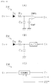
- FIG. 2 illustrates circuit diagrams showing example configurations of the time counting unit according to the present embodiment, wherein FIG. 2(A) shows a configuration including a CR integration circuit and a comparator, FIG. 2(B) shows a configuration including a CR integration circuit and an A/D converter, and FIG. 2(C) shows a configuration including a counter circuit;
- FIG. 3 is a time chart showing the relationship between ion current signal Si and output signal St of the comparison unit in the misfiring detection apparatus for an internal combustion engine according to the embodiment;
- FIG. 4(A) is a characteristic diagram showing misfiring detection by the misfiring detection apparatus for an internal combustion engine according to the embodiment;
- FIG. 4(B) is a characteristic diagram showing misfiring detection by the misfiring detection apparatus for an internal combustion engine according to a comparative example;
- FIG. 5 is a circuit diagram showing the configuration of the misfiring detection apparatus for an internal combustion engine according to another embodiment of the present invention; and
- FIG. 6 is an explanatory view showing components of an ion current signal detected by a conventional misfiring detection apparatus for an internal combustion engine.
-
- Reference numerals are used to identify selected items shown in the drawings as follows:
- 10: spark plug
- 10a: center electrode
- 10b: ground electrode
- 12: ignition coil
- 20, 20': ion current detection circuit
- 22: comparison unit (comparison means)
- 24: time counting unit (count means)
- 26: ECU (misfiring detection means)
-
- As shown in FIG. 1, the misfiring detection apparatus for an internal combustion engine (hereinafter referred to as a "misfiring detection apparatus") of the present embodiment detects misfiring of an internal combustion engine through utilization of ion current which flows, after spark discharge of a
spark plug 10 attached to the internal combustion engine, due to ions present in the vicinity of a center electrode 10a and a ground electrode 10b of thespark plug 10. The misfiring detection apparatus is mainly constituted by an ioncurrent detection circuit 20, acomparison unit 22, atime counting unit 24, and an engine control unit (hereinafter referred to as an "ECU") 26. - In a cylinder of the internal combustion engine, ions are generated during combustion after spark discharge by the
spark plug 10, and the resistance between the center electrode 10a and the ground electrode 10b varies depending on the amount of generated ions. In this respect, it has been elucidated that the amount of generated ions varies greatly depending on the state of combustion of the internal combustion engine; i.e., the operation conditions of the internal combustion engine. Therefore, when voltage is externally applied to thespark plug 10 after application of ignition voltage thereto and current flowing through thespark plug 10 is detected, a variation in the resistance between the electrodes of the spark plug; i.e., a variation in operation conditions, can be detected. - Before description of the configuration of the misfiring detection apparatus, a configuration for applying ignition voltage to the
spark plug 10 will be described briefly. - One end of a secondary winding L2 of an
ignition coil 12 is connected to the center electrode 10a of thespark plug 10; and the other of the secondary winding L2 of theignition coil 12 is connected to the ground electrode 10b of thespark plug 10 via the ioncurrent detection circuit 20. - A positive terminal of a battery BATT is connected to one end of a primary winding L1 of the
ignition coil 12; and a negative terminal of the battery BATT is connected to the other end of the primary winding L1 of theignition coil 12 via a switching element SW. The base terminal of the switching element SW is connected to theECU 26. The switching element SW is turned on and off by means of an IG signal from theECU 26. - When the
ECU 26 establishes and breaks electrical continuity between the emitter and collector of the switching element SW, a high voltage (several tens of kV) corresponding to the turn ratio (L1 : L2) of theignition coil 12 is generated across the secondary winding L2 of theignition coil 12. Thus, spark discharge occurs between the electrodes (the center electrode 10a and the ground electrode 10b) of thespark plug 10 due to the high voltage supplied from the secondary winding L2. - Next, the configuration of the misfiring detection apparatus will be described with reference to FIGS. 1 to 3.
- The ion
current detection circuit 20 is constituted by Zener diodes ZD1 and ZD2, a capacitor C11, and a resistor R11. - The Zener diode ZD1 has a Zener voltage of, for example, 300 V and serves as a voltage regulation diode. The Zener diode ZD1 is connected between the secondary winding L2 of the
ignition coil 12 and the ground. That is, the cathode terminal of the Zener diode ZD1 is connected to the other end of the secondary winding L2; and the anode terminal thereof is grounded. - The capacitor C11 and the resistor R11 are connected in series. The capacitor C11 end of the series circuit is connected to the cathode terminal of the Zener diode ZD1, and the resistor R11 end of the series circuit is grounded, so that the capacitor C11 and the resistor R11 are disposed between the cathode terminal of the Zener diode ZD1 and the ground. Further, the Zener diode ZD2 is connected in parallel to the resistor R11 such that the cathode terminal of the Zener diode ZD2 is grounded. The Zener diode ZD2 has a Zener voltage lower than the input limit voltage (permitted maximum input voltage) of the
comparison unit 22. - In the ion
current detection circuit 20 having the above-described configuration, upon occurrence of spark discharge at thespark plug 10, discharge current flows in the direction of arrow A in FIG. 1; i.e., discharge current flows from the secondary winding L2 of theignition coil 12 toward the ground via the capacitor C 11 and the Zener diode ZD2 (in the direction of arrow B). As a result, charge corresponding to 300 V is accumulated in the capacitor C11 due to action of the Zener diode ZD1. - After completion of the spark discharge of the
spark plug 10, ions are generated between the electrodes (the center electrode 10a and the ground electrode 10b) of thespark plug 10, so that a current path is formed by means of ions. Thus, due to the charge accumulated in the capacitor C11, current flows in the direction of arrow C in FIG. 1; i.e., the direction opposite the direction of arrow A for discharge current, via the secondary winding L2 of theignition coil 12, thespark plug 10, and the resistor R11. That is, ion current flows between the electrodes of thespark plug 10; and voltage corresponding to the amplitude of the ion current is generated across the resistor R11. Therefore, the amplitude of the ion current can be detected through detection of the voltage, which is output as an ion current signal S1 from the node between the resistor R11 and the capacitor C11. - Since the Zener diode ZD2 has a Zener voltage lower than the input limit voltage (permitted maximum input voltage) of the
comparison unit 22, as shown in FIG. 3, excessively high voltage is not input to the input terminal of thecomparison unit 22. Therefore, even when the peak value of discharge noise components varies depending on the state of combustion in the relevant cylinder, no discharge noise component having a voltage greater than the input limit voltage of thecomparison unit 22 is input to thecomparison unit 22. Accordingly, failure of thecomparison unit 22 due to such an excessively large input can be avoided. A broken line in FIG. 3 represents portions of the discharge noise component removed by the Zener diode ZD2. - The
comparison unit 22 includes a comparator, a reference voltage source, and other components. Thecomparison unit 22 compares the absolute value of the ion current signal S 1 output from the ioncurrent detection circuit 20 with a predetermined reference voltage and outputs comparison results to an output terminal. Specifically, the comparator of thecomparison unit 22 compares the voltage level of the signal (ion current signal Si) input to the one input terminal with a reference voltage input to the other input terminal. - The reference voltage source of the
comparison unit 22 determines a "threshold value" used for judging whether the voltage level of the ion current signal Si is high or low. In the case in which, as shown in FIG. 3, the ion current signal Si varies in the negative direction when discharge voltage becomes positive, the threshold voltage is set to a voltage which is lower by a predetermined amount than a voltage level in the steady state in which no discharge occurs. In the case in which the ion current signal Si varies in the positive direction when discharge voltage becomes positive, the threshold voltage is set to a voltage which is higher by a predetermined amount than the voltage level in the steady state in which no discharge occurs. - When an ion current signal Si having a voltage level higher than the threshold voltage is input to the
comparison unit 22, an L-level output signal is output from the output terminal of thecomparison unit 22. When an ion current signal Si having a voltage level lower than the threshold voltage is input to thecomparison unit 22, an H-level output signal is output from the output terminal of thecomparison unit 22. Therefore, as shown in FIG. 3, the H-level of the output signal St from thecomparison unit 22 represents presence of an ion current component or a discharge noise component. - The ECU (engine control unit) 26 includes a main storage device, a micro computer containing various registers, an input/output interface, and other components. The ECU performs various electronic controls in relation to the internal combustion engine.
- In the misfiring detection apparatus of the present embodiment, the
ECU 26 has a function of controlling the timing of turning the switching element on and off, and a function of judging that misfiring has occurred in the cylinder of the internal combustion engine when the time-accumulated value output from thetime counting unit 24 is not greater than a predetermined value. - The
time counting unit 24 is disposed in a stage following thecomparison unit 22, and, as shown in FIG. 2(A), includes a diode D0, a resistor R0, a capacitor C0, a comparator CMP0, and a comparison voltage source Vref. - Specifically, the diode D0 is connected in series to the output terminal St of the
comparison unit 22 while being oriented in the forward direction; and the resistor R0 is connected to the cathode terminal of the diode D0, so that the diode Do and the resistor R0 are connected in series. Further, the capacitor C0 is disposed between the ground and a terminal of the resistor R0 opposite the diode D0. When the diode D0, the resistor R0, and the capacitor C0 are connected in the above-described manner, the resistor R0 and the capacitor C0 constitute a CR integration circuit, and the diode D0 prevents reverse flow of charge from the capacitor C0 toward thecomparison unit 22. - The output terminal of the CR integration circuit constituted by the resistor R0 and the capacitor C0 is connected to the inverted input terminal of the comparator CMP0; and the comparison voltage source Vref is connected to the non-inverted input terminal of the comparator CMP0. Therefore, the comparator CMP0 compares the voltage level of the signal input to the inverted input terminal with voltage output from the comparison voltage source Vref and outputs a comparison result to the output terminal as an output signal Σt (digital signal). That is, the voltage output from the comparison voltage source Vref is set in such a manner that the comparator CMP0 outputs the output signal Σt when the amount of charge accumulated in the CR integration circuit exceeds a predetermined level.
- Since the
comparison unit 22 is configured in the above-described manner, periods of time over which thecomparison unit 22 outputs the output signal St can be integrated, or counted. Further, as shown in FIG. 3, when the counted period of time reaches a predetermined period of time, this can be detected on the basis of the output signal Σt of the comparator CMP0. - In other words, since the ion current component of the ion current signal Si is grasped as a cumulative value of generation periods thereof, the ion current can be grasped as a count value of time-related values, not as a cumulative value of current-related values. Therefore, even when the ion current contains a discharge noise component, the discharge noise component having a short duration accounts for only a small portion of the cumulative value, so that influence of the discharge noise component can be reduced. Accordingly, the
ECU 26 can detect misfiring in the cylinder with improved accuracy by detecting, on the basis of the output signal Σt of the comparator CMP0, that the time-accumulated value obtained by thetime counting unit 24 is not greater than the predetermined value. - Further, in the
time counting unit 24, the count means is realized by the CR integration circuit constituted by the resistor R0 and the capacitor C0, which is an analog circuit. Therefore, the cumulative period of time during which the ion current exceeds a predetermined current value can be detected as an analog value until the cumulative period of time reaches a predetermined period of time. This enables variation in the cumulative period of time to be detected as a continuous variable. Accordingly, expectedly, the accuracy of misfiring detection by theECU 26 can be improved. - FIGS. 2(B) and 2(C) show modifications of the
time counting unit 24. - In the
time counting unit 24 shown in FIG. 2(B), in place of the comparator CMP0, an A/D converter is provided in a stage succeeding the above-described CR integration circuit. - In this modification, since the A/D converter is provided in a stage succeeding the CR integration circuit constituted by the resistor R0 and the capacitor C0, an analog signal output from the above-described CR integration circuit can be converted by the A/D converter to a digital signal serving as the output signal Σt. Thus, ion current detected in the form of time count can be grasped as more detailed digital data. Accordingly, expectedly, the accuracy of misfiring detection by the
ECU 26 can be improved further. - The
time counting unit 24 shown in FIG. 2(c) is constituted by a digital counter circuit. - In this modification, the output signal St of the
comparison unit 22 is input to the input terminal of a digital counter COUNT. The digital counter COUNT samples the output signal St of thecomparison unit 22 at predetermined sampling intervals (CLK) and increments the count value. When the count value reaches a predetermined count value, the digital counter COUNT outputs the output signal Σt. Further, when a reset signal is input to the reset terminal, the count value is reset to an initial value. This configuration enables counting of a period during which thecomparison unit 22 outputs the output signal St, and making judgment on the basis of the time count value, as in the above-described case in which judgment on the basis of the time count is performed by the comparator CMP0. - In other words, since the
time counting unit 24 is constituted by a digital counter circuit, the cumulative period of time during which the ion current exceeds a predetermined current value can be detected as a digital value until the cumulative period of time reaches a predetermined period of time. Accordingly, the signal processing performed by theECU 26 can be simplified further. - FIG. 4 shows results of a comparison experiment in which correctness of judgment which the above-described misfiring detection apparatus made in relation to detection of misfiring was evaluated for the case of firing and the case of misfiring.
- As shown in FIG. 4(B), in the case of a conventional misfiring detection apparatus which integrates ion current, since many discharge noise components are integrated together with an ion current component (see FIG. 6), a misfire judgment area and a fire judgment area are close to each other due to errors in these areas. That is, there may be a case in which firing fails even when firing is detected and a case in which firing is effected properly even when misfiring is detected.
- By contrast, in the misfiring detection apparatus of the present embodiment, since the ion current is grasped not as a cumulative value of current-related values but as a cumulative value of time-related values, even when the ion current contains a discharge noise component, the discharge noise component having a short duration accounts for only a small portion of the cumulative value. Therefore, as shown in FIG. 4(A), it was confirmed that a misfire judgment area and a fire judgment area are not close to each other; and therefore the
ECU 26 can detect misfiring in the relevant cylinder reliably. - As described above, in the misfiring detection apparatus of the present embodiment, the
comparison unit 22 and thetime counting unit 24 accumulate periods of time during which the ion current flowing between the center electrode 10a and the ground electrode 10b of thespark plug 10 exceeds a predetermined current value; and theECU 26 judges that misfiring has occurred when a total of the accumulated periods is not greater than a predetermined value. Thus, the ion current can be grasped as a cumulative value of generation periods thereof. Therefore, even when the ion current contains a discharge noise component, the discharge noise component having a short duration accounts for only a small portion of the cumulative value, so that influence of the discharge noise component can be reduced. Accordingly, detection of misfiring can be performed with improved accuracy. - Moreover, in the misfiring detection apparatus of the present embodiment, the
comparison unit 22 judges whether the ion current is not less than the predetermined current value through comparison therebetween and outputs a comparison result; and thetime counting unit 24 counts periods of time during which the comparison result indicating that the. ion current is not less than the predetermined current value is output. Thus, the function of accumulating periods of time during which the ion current exceeds a predetermined current value can be realized by thecomparison unit 22 and thetime counting unit 24. Therefore, the accuracy in misfiring detection can be improved with relative ease. - A misfiring detection apparatus according to another embodiment which includes an ion current detection circuit 20', which is a modification of the ion
current detection circuit 20, will be described with reference to FIG. 5. Structural portions substantially identical with those of the ioncurrent detection circuit 20 are denoted by the same reference numerals and letters, and their repeated descriptions are omitted. - The ion current detection circuit 20' is effective in the case in which the
spark plug 10 causes so-called positive discharge, and, as shown in FIG. 5, is constituted by diodes D21 and D22, a Zener diode ZD, an ion current power source Vion, and a resistor R21. - The diode D21 is connected in series between the secondary winding L2 of the
ignition coil 12 and thespark plug 10, while being oriented forward toward thespark plug 10. The diode D21 prevents flow of current from the ion current power source Vion toward theignition coil 12. The cathode terminal of the diode D22 is connected to the cathode terminal of the diode D21, and the positive terminal of the ion current power source Vion is connected to the anode terminal of the diode D22. The diode D22 prevents application of voltage from the secondary winding L2 of theignition coil 12 to the ion current power source Vion. - The resistor R21 is disposed between the negative terminal of the ion current power source Vion and the ground. The resister R21 enables detection, as a voltage value, of ion current which is caused to flow between the electrodes of the
spark plug 10 by the ion current power source Vion. Further, the Zener diode ZD is connected in parallel to the resistor R21 such that the cathode terminal of the Zener diode ZD is grounded. The Zener diode ZD has a Zener voltage lower than the input limit voltage of thecomparison unit 22. - In the ion current detection circuit 20' having the above-described configuration, when the voltage of the center electrode 10a of the
spark plug 10 becomes lower than the voltage of the ion current power source Vion after completion of spark discharge caused by means of the secondary winding L2 of theignition coil 12, ion current originating from the ion current power source Vion flows through the gap between the electrodes of thespark plug 10 via the diode D22 and the resistor R21. Since a voltage corresponding to the ion current is generated between the opposite ends of the resistor R21, an ion current signal S1 can be obtained through detection of that voltage as in the case of the above-described ioncurrent detection circuit 20. - Moreover, as in the case of the Zener diode ZD2 of the above-described ion
current detection circuit 20, the Zener diode ZD has a Zener voltage lower than the input limit voltage of thecomparison unit 22, so that excessively high voltage is not input to the input terminal of thecomparison unit 22. Therefore, even when the peak value of discharge noise components varies depending on the state of combustion in the relevant cylinder, no discharge noise component having a voltage greater than the input limit voltage of thecomparison unit 22 is input to thecomparison unit 22. Accordingly, failure of thecomparison unit 22 due to such an excessively large input can be avoided. - Use of the misfiring detection apparatus including the ion current detection circuit 20' enables easy obtainment of the ion current signal Si even when the
spark plug 10 causes so-called positive discharge. Accordingly, even in the case of thespark plug 10 being of a positive discharge type, the accuracy of misfiring detection can be improved with relative ease. - In the invention of claim 1, the accumulating means accumulates periods of time during which the ion current flowing between the center and ground electrodes of a spark plug exceeds a predetermined current value; and the misfiring detection means judges that misfiring has occurred when a total of periods accumulated by the accumulating means is not greater than a predetermined value. Thus, the ion current can be grasped as a cumulative value of generation periods thereof. That is, since the ion current is grasped not as a cumulative value of current-related values but as a cumulative value of time-related values, even when the ion current contains a discharge noise component, the discharge noise component having a short duration accounts for only a small portion of the cumulative value. Accordingly, influence of the discharge noise component can be reduced, and thus the accuracy in misfiring detection can be improved.
- In the invention of
claim 2, the accumulating means includes comparison means and count means. The comparison means judges whether the ion current is not less than the predetermined current value through comparison therebetween and outputs a comparison result. That count means counts periods of time during which the comparison result indicating that the ion current is not less than the predetermined current value is output. Thus, the function of accumulating periods of time during which the ion current exceeds a predetermined current value can be realized by the comparison means and the count means. Therefore, the accuracy in misfiring detection can be improved with relatively ease. - In the invention of claim 3, since the count means includes a CR integration circuit, the count means can be realized by an analog circuit. Thus, the cumulative period of time during which the ion current exceeds a predetermined current value can be detected as an analog value. Therefore, expectedly, the accuracy in misfiring detection can be improved further.
- In the invention of claim 4, since the count means includes a digital counter circuit, the count means can be realized by a digital circuit. Thus, the cumulative period of time during which the ion current exceeds a predetermined current value can be detected as a digital value. Accordingly, signal processing by, for example, a microcomputer can be made easier.
Claims (4)
- Misfiring detection apparatus for an internal combustion engine for detecting a misfire in a cylinder of the internal combustion engine through measurement of ion current flowing between the center electrode (10a) and ground electrode (10b) of a spark plug (10) attached to the cylinder, said misfiring detection apparatus being characterized by comprising:accumulating means (22, 24) for accumulating a value representative of periods of time during which the ion current exceeds a predetermined current value; andmisfiring detection means (26) for judging that misfiring has occurred when a value representative of the total of the periods of time accumulated by the accumulating means (22, 24) is not greater than a predetermined value.
- A misfiring detection apparatus for an internal combustion engine according to Claim 1, wherein the accumulating means (22, 24) comprises:comparison means (22) for judging whether the ion current is not less than the predetermined current value through comparison therebetween and for outputting a comparison result; andcount means (24) for counting periods of time during which the comparison result indicating that the ion current is not less than the predetermined current value is output.
- A misfiring detection apparatus for an internal combustion engine according to Claim 2, wherein the count means (24) comprises a CR integration circuit.
- A misfiring detection apparatus for an internal combustion engine according to claim 2, wherein the count means (24) comprises a digital counter circuit.
Applications Claiming Priority (2)
| Application Number | Priority Date | Filing Date | Title |
|---|---|---|---|
| JP2000282128A JP2002089426A (en) | 2000-09-18 | 2000-09-18 | Misfire detection device for internal combustion engine |
| JP2000282128 | 2000-09-18 |
Publications (2)
| Publication Number | Publication Date |
|---|---|
| EP1188917A2 true EP1188917A2 (en) | 2002-03-20 |
| EP1188917A3 EP1188917A3 (en) | 2003-12-17 |
Family
ID=18766689
Family Applications (1)
| Application Number | Title | Priority Date | Filing Date |
|---|---|---|---|
| EP01307881A Withdrawn EP1188917A3 (en) | 2000-09-18 | 2001-09-17 | Misfiring detection apparatus for internal combustion engine |
Country Status (3)
| Country | Link |
|---|---|
| US (1) | US6715340B2 (en) |
| EP (1) | EP1188917A3 (en) |
| JP (1) | JP2002089426A (en) |
Cited By (1)
| Publication number | Priority date | Publication date | Assignee | Title |
|---|---|---|---|---|
| FR2839115A1 (en) * | 2002-04-26 | 2003-10-31 | Mitsubishi Electric Corp | IGNITION RATE DETECTION DEVICE FOR INTERNAL COMBUSTION ENGINE |
Families Citing this family (21)
| Publication number | Priority date | Publication date | Assignee | Title |
|---|---|---|---|---|
| US7063079B2 (en) | 2002-11-01 | 2006-06-20 | Visteon Global Technologies, Inc. | Device for reducing the part count and package size of an in-cylinder ionization detection system by integrating the ionization detection circuit and ignition coil driver into a single package |
| US6883509B2 (en) | 2002-11-01 | 2005-04-26 | Visteon Global Technologies, Inc. | Ignition coil with integrated coil driver and ionization detection circuitry |
| FR2879665B1 (en) * | 2004-12-17 | 2009-12-18 | Inst Francais Du Petrole | ABNORMAL COMBUSTION DETECTION METHOD FOR INTERNAL COMBUSTION ENGINES |
| JP4598582B2 (en) * | 2005-03-31 | 2010-12-15 | ダイヤモンド電機株式会社 | Ignition coil for internal combustion engine |
| JP4799200B2 (en) | 2006-02-06 | 2011-10-26 | ダイハツ工業株式会社 | Operation control method based on ion current of internal combustion engine |
| JP4619299B2 (en) * | 2006-02-06 | 2011-01-26 | ダイハツ工業株式会社 | Method for determining the combustion state of an internal combustion engine |
| FR2898640B1 (en) * | 2006-03-20 | 2008-04-25 | Siemens Vdo Automotive Sas | METHOD FOR TRANSMITTING INFORMATION RELATING TO THE OPERATION OF AN INTERNAL COMBUSTION ENGINE |
| JP2007315297A (en) * | 2006-05-26 | 2007-12-06 | Denso Corp | Combustion state determination device for internal combustion engine |
| JP5247993B2 (en) * | 2006-07-06 | 2013-07-24 | 株式会社デンソー | Ignition coil |
| JP4261573B2 (en) * | 2006-11-23 | 2009-04-30 | 日本特殊陶業株式会社 | Spark plug |
| JP2010077804A (en) * | 2008-08-28 | 2010-04-08 | Diamond Electric Mfg Co Ltd | Combustion control device for internal combustion engine |
| JP5207888B2 (en) * | 2008-09-05 | 2013-06-12 | ダイヤモンド電機株式会社 | Combustion control device for internal combustion engine |
| JP5318701B2 (en) * | 2009-08-17 | 2013-10-16 | ダイヤモンド電機株式会社 | Ion current detector |
| JP4981869B2 (en) * | 2009-10-15 | 2012-07-25 | 三菱電機株式会社 | Combustion state detection device for internal combustion engine |
| US8547104B2 (en) * | 2010-03-01 | 2013-10-01 | Woodward, Inc. | Self power for ignition coil with integrated ion sense circuitry |
| US8692526B2 (en) * | 2010-12-01 | 2014-04-08 | Microsoft Corporation | Converting leakage current to DC output |
| CN102418643B (en) * | 2011-08-08 | 2013-06-26 | 同济大学 | Apparatus and method for spark ignition engine misfire control |
| EP2810038B1 (en) * | 2012-01-30 | 2018-07-04 | SEM Aktiebolag | Method for monitoring a combustion engine |
| JP5988805B2 (en) * | 2012-09-25 | 2016-09-07 | ダイハツ工業株式会社 | Control device for internal combustion engine |
| JP6698906B1 (en) * | 2019-04-02 | 2020-05-27 | 三菱電機株式会社 | Internal combustion engine discharge state detection device |
| WO2021260444A1 (en) * | 2020-06-25 | 2021-12-30 | Tvs Motor Company Limited | Event detection system |
Citations (1)
| Publication number | Priority date | Publication date | Assignee | Title |
|---|---|---|---|---|
| JPH0454283A (en) | 1990-06-25 | 1992-02-21 | Mitsubishi Electric Corp | Internal combustion engine misfire detector and method |
Family Cites Families (6)
| Publication number | Priority date | Publication date | Assignee | Title |
|---|---|---|---|---|
| KR950004612B1 (en) | 1990-06-25 | 1995-05-03 | 미쓰비시덴키가부시키가이샤 | Apparatus and method for detecting misfiring in internal combustion engine |
| JP3150429B2 (en) | 1992-07-21 | 2001-03-26 | ダイハツ工業株式会社 | Lean limit detection method using ion current |
| JP2909345B2 (en) | 1993-03-23 | 1999-06-23 | 三菱電機株式会社 | Internal combustion engine control device |
| FR2734022B1 (en) * | 1995-05-10 | 1998-06-26 | Nippon Soken | APPARATUS FOR MONITORING COMBUSTION IN AN INTERNAL COMBUSTION ENGINE |
| US5925819A (en) | 1995-05-10 | 1999-07-20 | Nippon Soken, Inc. | Combustion monitoring apparatus for internal combustion engine |
| JP3441909B2 (en) * | 1997-02-07 | 2003-09-02 | 三菱電機株式会社 | Device for detecting combustion state of internal combustion engine |
-
2000
- 2000-09-18 JP JP2000282128A patent/JP2002089426A/en active Pending
-
2001
- 2001-09-17 EP EP01307881A patent/EP1188917A3/en not_active Withdrawn
- 2001-09-17 US US09/953,131 patent/US6715340B2/en not_active Expired - Fee Related
Patent Citations (1)
| Publication number | Priority date | Publication date | Assignee | Title |
|---|---|---|---|---|
| JPH0454283A (en) | 1990-06-25 | 1992-02-21 | Mitsubishi Electric Corp | Internal combustion engine misfire detector and method |
Cited By (1)
| Publication number | Priority date | Publication date | Assignee | Title |
|---|---|---|---|---|
| FR2839115A1 (en) * | 2002-04-26 | 2003-10-31 | Mitsubishi Electric Corp | IGNITION RATE DETECTION DEVICE FOR INTERNAL COMBUSTION ENGINE |
Also Published As
| Publication number | Publication date |
|---|---|
| US6715340B2 (en) | 2004-04-06 |
| US20020033041A1 (en) | 2002-03-21 |
| EP1188917A3 (en) | 2003-12-17 |
| JP2002089426A (en) | 2002-03-27 |
Similar Documents
| Publication | Publication Date | Title |
|---|---|---|
| US6715340B2 (en) | Misfiring detection apparatus for internal combustion engine | |
| US5215067A (en) | Misfire-detecting system for internal combustion engines | |
| US6418785B1 (en) | Misfire detecting apparatus for internal combustion engine | |
| US6766243B1 (en) | Device and method for ignition in an internal combustion engine | |
| US5388560A (en) | Misfire-detecting system for internal combustion engines | |
| JPH05164034A (en) | Misfire detection device for internal combustion engine | |
| JP2678986B2 (en) | Misfire detection device for internal combustion engine | |
| US5418461A (en) | Device for detecting abnormality of spark plugs for internal combustion engines and a misfire-detecting system incorporating the same | |
| JPH09195913A (en) | Device for detecting combustion state of internal combustion engine | |
| EP0715075B1 (en) | Misfire detecting device for internal combustion engine | |
| US5821754A (en) | Ignition system for an internal combustion engine | |
| US5327867A (en) | Misfire-detecting system for internal combustion engines | |
| US5510715A (en) | Apparatus for determining the ignition characteristic of an internal combustion engine | |
| JP2880058B2 (en) | Misfire detection device for internal combustion engine | |
| US5322045A (en) | Misfire-detecting system for internal combustion engines | |
| US5294888A (en) | Device for detecting misfire of an internal combustion engine by comparing voltage waveforms associated with ignition system | |
| US6948484B2 (en) | Capacitor discharge ignition device | |
| JP4830991B2 (en) | Ignition control device for internal combustion engine | |
| JP3877108B2 (en) | Internal combustion engine knock detection device | |
| US6263727B1 (en) | Make voltage bias ion sense misfired detection system | |
| JPH08135554A (en) | Internal combustion engine misfire detection circuit | |
| JP2754503B2 (en) | Misfire detection device for internal combustion engine | |
| JP2002180949A (en) | Ignition device for internal combustion engine provided with ion current detection device | |
| US5415148A (en) | Misfire-detecting system for internal combustion engines | |
| US6278278B1 (en) | Measuring and diagnostic device for an ignition system of an internal combustion engine |
Legal Events
| Date | Code | Title | Description |
|---|---|---|---|
| PUAI | Public reference made under article 153(3) epc to a published international application that has entered the european phase |
Free format text: ORIGINAL CODE: 0009012 |
|
| AK | Designated contracting states |
Kind code of ref document: A2 Designated state(s): AT BE CH CY DE DK ES FI FR GB GR IE IT LI LU MC NL PT SE TR |
|
| AX | Request for extension of the european patent |
Free format text: AL;LT;LV;MK;RO;SI |
|
| PUAL | Search report despatched |
Free format text: ORIGINAL CODE: 0009013 |
|
| AK | Designated contracting states |
Kind code of ref document: A3 Designated state(s): AT BE CH CY DE DK ES FI FR GB GR IE IT LI LU MC NL PT SE TR |
|
| AX | Request for extension of the european patent |
Extension state: AL LT LV MK RO SI |
|
| AKX | Designation fees paid | ||
| REG | Reference to a national code |
Ref country code: DE Ref legal event code: 8566 |
|
| STAA | Information on the status of an ep patent application or granted ep patent |
Free format text: STATUS: THE APPLICATION IS DEEMED TO BE WITHDRAWN |
|
| 18D | Application deemed to be withdrawn |
Effective date: 20040618 |