EP1188650A1 - Detachable lamp - Google Patents
Detachable lamp Download PDFInfo
- Publication number
- EP1188650A1 EP1188650A1 EP01203056A EP01203056A EP1188650A1 EP 1188650 A1 EP1188650 A1 EP 1188650A1 EP 01203056 A EP01203056 A EP 01203056A EP 01203056 A EP01203056 A EP 01203056A EP 1188650 A1 EP1188650 A1 EP 1188650A1
- Authority
- EP
- European Patent Office
- Prior art keywords
- housing
- support
- present
- contact
- lamp
- Prior art date
- Legal status (The legal status is an assumption and is not a legal conclusion. Google has not performed a legal analysis and makes no representation as to the accuracy of the status listed.)
- Granted
Links
- 238000010276 construction Methods 0.000 description 3
- 238000007789 sealing Methods 0.000 description 3
- 230000000694 effects Effects 0.000 description 2
- 239000007787 solid Substances 0.000 description 2
- 230000005540 biological transmission Effects 0.000 description 1
- 230000006835 compression Effects 0.000 description 1
- 238000007906 compression Methods 0.000 description 1
- 239000011521 glass Substances 0.000 description 1
- 239000000463 material Substances 0.000 description 1
- 230000000717 retained effect Effects 0.000 description 1
Images



Classifications
-
- B—PERFORMING OPERATIONS; TRANSPORTING
- B62—LAND VEHICLES FOR TRAVELLING OTHERWISE THAN ON RAILS
- B62J—CYCLE SADDLES OR SEATS; AUXILIARY DEVICES OR ACCESSORIES SPECIALLY ADAPTED TO CYCLES AND NOT OTHERWISE PROVIDED FOR, e.g. ARTICLE CARRIERS OR CYCLE PROTECTORS
- B62J6/00—Arrangement of optical signalling or lighting devices on cycles; Mounting or supporting thereof; Circuits therefor
Definitions
- the invention relates to a detachable lamp comprising a housing and a support to be attached to a vehicle, to which the housing can be detachably connected, whilst a light source is present in the housing, which light source is connected for its power supply to at least one connection contact in the housing, which connection contact is present on a carrier that is mounted within said housing.
- Such a detachable lamp is known from German patent application no. 31 44 034.
- the housing of the lamp was connected to the support by means of a dovetail connection.
- a hole is formed in the wall of the housing thereby, through which hole a bent part of a contact spring extends so as to make contact, when the housing of the lamp is being slid onto said support, with a contact that is connected to said support, which contact is present in a surface of the dovetail connection that forms part of the support.
- said support is made up of a substantially U-shaped bracket, wherein at least one of the legs of the bracket to be inserted into the housing for the purpose of fitting the housing on the bracket is provided at its free ends with a further connection contact, which, in the position in which the housing is mounted on the support, is in connection with means present on the carrier for transmitting power from a power source connected to said further connection contact on the support to the connection contact that is connected to the light source.
- bracket-like support makes it possible to effect a solid connection between the housing and the support, whilst the connection contact that is present in the housing is adequately protected, also in the position in which the housing is detached from the support. Also the connection between the connection contact that is present on the free end of the leg of the bracket and the power transmission means present on the carrier will be adequately protected in the interior of the housing in the position in which the lamp is fitted on the support and not be exposed to moisture and the like in unfavourable weather conditions.
- Figure 1 is a bottom plan view of a lamp according to the invention.
- Figure 2 is a side elevation of the lamp of Figure 1.
- Figure 3 is a sectional view over the lamp of Figures 1 and 2, along the line III-III in Figure 1.
- Figure 4 is a sectional view of the lamp of Figures 1 and 2, along the line IV-IV in Figure 1.
- Figure 5 is a perspective view, seen from above, of the lamp as shown in the preceding figures, seen after a cover has been removed from the housing of the lamp.
- Figure 6 is a perspective view of a number of components of the lamp shown in the preceding figures.
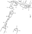
- Figure 7 is a perspective view of spaced-apart parts of the carrier and of the support.
- Figure 8 is a larger-scale, bottom plan view of a part of the lamp as shown in the preceding figures, wherein the parts are spaced apart.
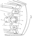
- Figure 9 is also a larger-scale, bottom plan view of the lamp, seen from a different angle, wherein the parts are spaced apart.
- the lamp comprises a housing 1, whose interior can be closed by means of a cover 2.
- a mirror 3 is mounted in an open end of housing 1, which mirror is covered by means of a glass 4 at the open end of the housing.
- a light source for example an incandescent lamp 5.
- housing 1 Mounted in housing 1 is a carrier in the form of a so-called printed circuit board 6 (Figure 5). Said printed circuit board, among other parts, is not shown in Figures 3 and 4 for easy reference.
- connection contacts in the form of contact springs 7 and 8, which abut against one end of the incandescent lamp 5 in a usual manner.
- the housing of the lamp can be detachably placed on a support 9, which is made up of a substantially U-shaped bracket, which is made of a tubular material.
- Sealing caps 10 are inserted in the ends of tubular support 9. Contact points 11 are present on the free ends of said sealing caps, to which contact points the ends of electrical wires 12 are connected. Said electrical wires can be passed outwards through openings 13, which are provided near the two legs of the U-shaped support 9, for example for connection to a power source, such as a dynamo, and/or for connection to a rear light of the vehicle on which the lamp will be present.
- a power source such as a dynamo
- the printed circuit board or carrier 6 includes two contact points in the form of contact springs 14 and 15, against which the contact points or further connection contacts 11 of support 9 will abut when the housing of the lamp is present on support 9.
- channel-like recesses bounded by wall parts 16 are formed in the housing 1 of the lamp, into which recesses the parallel legs of support 9 can be inserted, whereby the contact points 11 will come into contact with the contact springs 14 and 15 and depress said contact springs slightly so as to ensure a proper contact between the contact springs 14 and 15 and the contact points 11.
- a contact spring 17 mounted on the carrier or printed circuit board 6 will abut against the outside of the support 9 so as to effect a mass connection of the carrier or printed circuit board 6 to the frame of the vehicle via support 9.
- a further mass connection can be effected by means of a wire 18 passed through support 9, which is inserted, with one end thereof, into an opening 10a in the sealing cap 10, and with which the contact spring 17 can come into contact.
- the support 9 that is inserted into housing 1 can be locked in position within said housing by means of a locking yoke 19 which is disposed in the housing.
- Locking yoke 19 is centrally provided with an opening, in which a pin 20 is freely rotatably supported.
- pin 20 Present on the notched end of pin 20 are two cams 21.
- said cams will initially be slightly pressed together and subsequently, after having passed the opening, spring outwards again to as to prevent pin 20 being pulled out of the hole in yoke 19, since the yoke is retained between the cams 21 and a head 22 of pin 20 located at the end of pin 20 remote from said cams 21.
- In the head 22 there have been made notches 23.
- Pin 20 can be turned about its longitudinal axis by means of a specially shaped key (not shown), which is provided with projections that fit in said notches 23.
- pin 20 on which said cams are present is surrounded by the end of a compression spring 24, which, in the fully mounted condition of the lamp, is confined between the cover 2 and the side of the yoke 19 that faces towards the cover. Furthermore, said pin is passed through a hole that is formed in the wall of the housing remote from the cover, in such a manner that head 22 will be accessible from outside housing 1.
- cams 26 When said cams 26 are positioned opposite recesses 27 formed in housing 1, pin 22 can be moved in housing 1 so as to move the locking yoke against the action of spring 24 by means of cams 26.
- cams 26 By turning pin 20 about is longitudinal axis, cams 26 will be positioned opposite stop surfaces 28 of the housing, as a result of which pin 20 will be locked against movement in its longitudinal direction.
- holes are present in the locking yoke 19, through which holes bolts 29 extend, by means of which bolts the cover 2 is fixed to the housing 1.
- the housing furthermore accommodates batteries 30, which are connected to a contact point 31 on the carrier or printed circuit board 6. Furthermore, a connection element 32 is present on said carrier or printed circuit board, which connection element is accessible, via an opening 33 in the housing, for connecting an adapter by means of which the batteries can be recharged.
- carrier or printed circuit board 6 Furthermore present on carrier or printed circuit board 6 is a pressure switch 34 for turning the lamp on and off. Said switch can be operated via a depressable part of the cover 2.
- light diodes 35 are mounted on the printed circuit board, which light diodes are visible through the transparent parts of the cover, so that the user of the vehicle will be able to check the operation of the lamp. It will be apparent that the various parts that are mounted on printed circuit board 6 will be suitably interconnected via the wiring on the printed circuit board.
- Support 9 can be attached to the frame of a bicycle or the like vehicle, and be put in a desired position thereby, by means of a usual clamping element.
- connection contacts on the support and on the printed circuit board can be accommodated within the housing, where they are adequately protected. Housing can be readily connected to the support 9 and be detached therefrom without much effort.
- the contact points on the ends of the support can be of sturdy construction.
Landscapes
- Engineering & Computer Science (AREA)
- Mechanical Engineering (AREA)
- Fastening Of Light Sources Or Lamp Holders (AREA)
- Lighting Device Outwards From Vehicle And Optical Signal (AREA)
Abstract
Description
- The invention relates to a detachable lamp comprising a housing and a support to be attached to a vehicle, to which the housing can be detachably connected, whilst a light source is present in the housing, which light source is connected for its power supply to at least one connection contact in the housing, which connection contact is present on a carrier that is mounted within said housing.
- Such a detachable lamp is known from German patent application no. 31 44 034. With this prior art construction, the housing of the lamp was connected to the support by means of a dovetail connection. A hole is formed in the wall of the housing thereby, through which hole a bent part of a contact spring extends so as to make contact, when the housing of the lamp is being slid onto said support, with a contact that is connected to said support, which contact is present in a surface of the dovetail connection that forms part of the support.
- In the position in which the lamp is detached from the support, the part of the contact spring that projects outside the housing is liable to damage. Furthermore, it is not possible thereby to obtain a solid connection between the housing and the support whilst ensuring a proper electrical contact between the various parts.
- According to the invention, said support is made up of a substantially U-shaped bracket, wherein at least one of the legs of the bracket to be inserted into the housing for the purpose of fitting the housing on the bracket is provided at its free ends with a further connection contact, which, in the position in which the housing is mounted on the support, is in connection with means present on the carrier for transmitting power from a power source connected to said further connection contact on the support to the connection contact that is connected to the light source.
- The use of the bracket-like support makes it possible to effect a solid connection between the housing and the support, whilst the connection contact that is present in the housing is adequately protected, also in the position in which the housing is detached from the support. Also the connection between the connection contact that is present on the free end of the leg of the bracket and the power transmission means present on the carrier will be adequately protected in the interior of the housing in the position in which the lamp is fitted on the support and not be exposed to moisture and the like in unfavourable weather conditions.
- The invention will now be explained in more detail with reference to the accompanying figures, which show a possible embodiment of a lamp according to the invention.
- Figure 1 is a bottom plan view of a lamp according to the invention.
- Figure 2 is a side elevation of the lamp of Figure 1.
- Figure 3 is a sectional view over the lamp of Figures 1 and 2, along the line III-III in Figure 1.
- Figure 4 is a sectional view of the lamp of Figures 1 and 2, along the line IV-IV in Figure 1.
- Figure 5 is a perspective view, seen from above, of the lamp as shown in the preceding figures, seen after a cover has been removed from the housing of the lamp.
- Figure 6 is a perspective view of a number of components of the lamp shown in the preceding figures.
- Figure 7 is a perspective view of spaced-apart parts of the carrier and of the support.
- Figure 8 is a larger-scale, bottom plan view of a part of the lamp as shown in the preceding figures, wherein the parts are spaced apart.
- Figure 9 is also a larger-scale, bottom plan view of the lamp, seen from a different angle, wherein the parts are spaced apart.
- As appears in particular from Figures 1 - 5, the lamp comprises a
housing 1, whose interior can be closed by means of acover 2. Amirror 3 is mounted in an open end ofhousing 1, which mirror is covered by means of a glass 4 at the open end of the housing. Disposed in said mirror is a light source, for example anincandescent lamp 5. - Mounted in
housing 1 is a carrier in the form of a so-called printed circuit board 6 (Figure 5). Said printed circuit board, among other parts, is not shown in Figures 3 and 4 for easy reference. - Mounted on printed
circuit board 6 are two connection contacts in the form ofcontact springs incandescent lamp 5 in a usual manner. - The housing of the lamp can be detachably placed on a
support 9, which is made up of a substantially U-shaped bracket, which is made of a tubular material. -
Sealing caps 10 are inserted in the ends oftubular support 9.Contact points 11 are present on the free ends of said sealing caps, to which contact points the ends ofelectrical wires 12 are connected. Said electrical wires can be passed outwards throughopenings 13, which are provided near the two legs of the U-shapedsupport 9, for example for connection to a power source, such as a dynamo, and/or for connection to a rear light of the vehicle on which the lamp will be present. - The printed circuit board or
carrier 6 includes two contact points in the form ofcontact springs further connection contacts 11 ofsupport 9 will abut when the housing of the lamp is present onsupport 9. - Furthermore, channel-like recesses bounded by
wall parts 16 are formed in thehousing 1 of the lamp, into which recesses the parallel legs ofsupport 9 can be inserted, whereby thecontact points 11 will come into contact with thecontact springs contact springs contact points 11. - In this position, also a
contact spring 17 mounted on the carrier or printedcircuit board 6 will abut against the outside of thesupport 9 so as to effect a mass connection of the carrier or printedcircuit board 6 to the frame of the vehicle viasupport 9. - Possibly, a further mass connection can be effected by means of a
wire 18 passed throughsupport 9, which is inserted, with one end thereof, into an opening 10a in the sealingcap 10, and with which thecontact spring 17 can come into contact. - The
support 9 that is inserted intohousing 1 can be locked in position within said housing by means of alocking yoke 19 which is disposed in the housing.Locking yoke 19 is centrally provided with an opening, in which apin 20 is freely rotatably supported. - Present on the notched end of
pin 20 are twocams 21. When the ends ofpin 20, on which thecams 21 are present, are inserted into the opening formed in thelocking yoke 19, said cams will initially be slightly pressed together and subsequently, after having passed the opening, spring outwards again to as to preventpin 20 being pulled out of the hole inyoke 19, since the yoke is retained between thecams 21 and ahead 22 ofpin 20 located at the end ofpin 20 remote fromsaid cams 21. In thehead 22 there have been madenotches 23.Pin 20 can be turned about its longitudinal axis by means of a specially shaped key (not shown), which is provided with projections that fit in saidnotches 23. - The
part 21 ofpin 20 on which said cams are present is surrounded by the end of acompression spring 24, which, in the fully mounted condition of the lamp, is confined between thecover 2 and the side of theyoke 19 that faces towards the cover. Furthermore, said pin is passed through a hole that is formed in the wall of the housing remote from the cover, in such a manner thathead 22 will be accessible fromoutside housing 1. - When the two legs of
support 9 are inserted intohousing 1, said legs will slide under the ends oflocking yoke 19 until said yoke ends are positioned oppositenotches 25 in the two legs ofsupport 9. In this position the ends of thelocking yoke 19 will be urged intonotches 25 by means ofspring 24, so thatsupport 9 is locked against being retracted from the housing. Said locking engagement can be released by exerting a pushing force on thehead 22 of the pin in the longitudinal direction of the pin, as a result of which the yoke will be pushed out of thenotches 25 by the pin. To this end, protrudingcams 26 are formed on the sides ofhead 22 that face towardscams 21, as appears in particular from Figure 9. When saidcams 26 are positionedopposite recesses 27 formed inhousing 1,pin 22 can be moved inhousing 1 so as to move the locking yoke against the action ofspring 24 by means ofcams 26. By turningpin 20 about is longitudinal axis,cams 26 will be positionedopposite stop surfaces 28 of the housing, as a result of whichpin 20 will be locked against movement in its longitudinal direction. - Furthermore, holes are present in the
locking yoke 19, through whichholes bolts 29 extend, by means of which bolts thecover 2 is fixed to thehousing 1. - As is furthermore shown in Figure 5, the housing furthermore accommodates
batteries 30, which are connected to acontact point 31 on the carrier or printedcircuit board 6. Furthermore, aconnection element 32 is present on said carrier or printed circuit board, which connection element is accessible, via anopening 33 in the housing, for connecting an adapter by means of which the batteries can be recharged. - Furthermore present on carrier or printed
circuit board 6 is apressure switch 34 for turning the lamp on and off. Said switch can be operated via a depressable part of thecover 2. In addition to this,light diodes 35 are mounted on the printed circuit board, which light diodes are visible through the transparent parts of the cover, so that the user of the vehicle will be able to check the operation of the lamp. It will be apparent that the various parts that are mounted on printedcircuit board 6 will be suitably interconnected via the wiring on the printed circuit board. -
Support 9 can be attached to the frame of a bicycle or the like vehicle, and be put in a desired position thereby, by means of a usual clamping element. - By mounting all the essential components, such as contact springs for connection to the dynamo, the headlight and the rear light and earth, the contact point for the charging adaptor, the switch and the light diodes, on a separate printed circuit board, an efficient and compact construction is obtained. The connection contacts on the support and on the printed circuit board can be accommodated within the housing, where they are adequately protected. Housing can be readily connected to the
support 9 and be detached therefrom without much effort. The contact points on the ends of the support can be of sturdy construction.
Claims (4)
- A detachable lamp comprising a housing and a support to be attached to a vehicle, to which the housing can be detachably connected, whilst a light source is present in the housing, which light source is connected for its power supply to at least one connection contact in the housing, which connection contact is present on a carrier that is mounted within said housing, characterized in that said support is made up of a substantially U-shaped bracket, wherein at least one of the legs of the bracket to be inserted into the housing for the purpose of fitting the housing on the bracket is provided at its free ends with a further connection contact, which, in the position in which the housing is present on the support, is in connection with means present on the carrier for transmitting power from a power source connected to said further connection contact on the support to the connection contact that is connected to the light source.
- A lamp according to claim 1, characterized in that said carrier is made up of a printed circuit board.
- A lamp according to claim 1, characterized in that said support comprises a leg to be inserted into the housing, on the end of which a connection contact in the form of a contact point is present, which abuts against a contact spring on said printed circuit board in the position in which the lamp is fitted on the support.
- A lamp according to any one of the preceding claims, characterized in that further connection contacts are present on the free ends of the two legs of said bracket.
Applications Claiming Priority (2)
| Application Number | Priority Date | Filing Date | Title |
|---|---|---|---|
| NL1016189A NL1016189C2 (en) | 2000-09-15 | 2000-09-15 | Detachable lamp. |
| NL1016189 | 2000-09-15 |
Publications (2)
| Publication Number | Publication Date |
|---|---|
| EP1188650A1 true EP1188650A1 (en) | 2002-03-20 |
| EP1188650B1 EP1188650B1 (en) | 2007-06-13 |
Family
ID=19772085
Family Applications (1)
| Application Number | Title | Priority Date | Filing Date |
|---|---|---|---|
| EP01203056A Expired - Lifetime EP1188650B1 (en) | 2000-09-15 | 2001-08-10 | Detachable lamp |
Country Status (3)
| Country | Link |
|---|---|
| EP (1) | EP1188650B1 (en) |
| DE (1) | DE60128872T2 (en) |
| NL (1) | NL1016189C2 (en) |
Families Citing this family (1)
| Publication number | Priority date | Publication date | Assignee | Title |
|---|---|---|---|---|
| NL1017081C2 (en) | 2001-01-11 | 2002-07-15 | Spanninga Metaal | Bicycle lighting device. |
Citations (4)
| Publication number | Priority date | Publication date | Assignee | Title |
|---|---|---|---|---|
| DE3144034A1 (en) | 1981-11-05 | 1983-05-26 | Werner 5000 Köln Westhoff | Lighting system, in particular for a bicycle |
| DE3642263A1 (en) * | 1986-06-12 | 1987-12-17 | Juergen Graefke | Bicycle lamp cartridge with insert |
| DE4320481A1 (en) * | 1993-06-21 | 1994-12-22 | Rixen & Kaul Gmbh | Bag with a flexurally rigid attachment for a vehicle, for example a bicycle |
| DE4337456A1 (en) * | 1993-11-03 | 1995-05-04 | S U M Sicherheitsleiteinrichtu | Continuous lighting device |
-
2000
- 2000-09-15 NL NL1016189A patent/NL1016189C2/en not_active IP Right Cessation
-
2001
- 2001-08-10 DE DE60128872T patent/DE60128872T2/en not_active Expired - Lifetime
- 2001-08-10 EP EP01203056A patent/EP1188650B1/en not_active Expired - Lifetime
Patent Citations (4)
| Publication number | Priority date | Publication date | Assignee | Title |
|---|---|---|---|---|
| DE3144034A1 (en) | 1981-11-05 | 1983-05-26 | Werner 5000 Köln Westhoff | Lighting system, in particular for a bicycle |
| DE3642263A1 (en) * | 1986-06-12 | 1987-12-17 | Juergen Graefke | Bicycle lamp cartridge with insert |
| DE4320481A1 (en) * | 1993-06-21 | 1994-12-22 | Rixen & Kaul Gmbh | Bag with a flexurally rigid attachment for a vehicle, for example a bicycle |
| DE4337456A1 (en) * | 1993-11-03 | 1995-05-04 | S U M Sicherheitsleiteinrichtu | Continuous lighting device |
Also Published As
| Publication number | Publication date |
|---|---|
| DE60128872T2 (en) | 2008-02-14 |
| EP1188650B1 (en) | 2007-06-13 |
| DE60128872D1 (en) | 2007-07-26 |
| NL1016189C2 (en) | 2002-03-18 |
Similar Documents
| Publication | Publication Date | Title |
|---|---|---|
| MXPA03002339A (en) | Electrical terminal socket assembly for vehicular component. | |
| KR880001458A (en) | Automotive Sun Visor Assembly | |
| KR20010085513A (en) | Electric connector having press contact unit | |
| JP5444075B2 (en) | Switch device | |
| CN100423152C (en) | Steering switch device | |
| GB2263972A (en) | Lighting fixture with switch | |
| JP2584294Y2 (en) | Shift lever device for automatic transmission | |
| US5651450A (en) | Switches, in particular switches that can be installed into the instrument panel of a vehicle, and a method for manufacturing a switch | |
| EP1188650A1 (en) | Detachable lamp | |
| EP0896351A3 (en) | Device for mechanical coupling of an overcurrent relay to a contactor | |
| KR200453730Y1 (en) | Improved fluorescent lamp socket | |
| FI81461C (en) | ANORDING FOR INKOPPLING AV EN HJAELPBRYTARE. | |
| WO2004047228B1 (en) | Improved memory card connector | |
| EP1204178A3 (en) | Connector with switch | |
| TW502882U (en) | ZIF socket with improved lever mechanism | |
| US20070297186A1 (en) | Clamp light | |
| US3156416A (en) | Lamp housing | |
| JP2004063112A (en) | Switch for handlebar | |
| EP0882644B1 (en) | Lighting device for a case-platform combination for vehicles of motorcycle type | |
| EP1253676A3 (en) | Electrical plug connector | |
| GB2130014A (en) | Electrical switch means | |
| US4055739A (en) | Lighted toggle lever switch | |
| FR2827702A1 (en) | DEVICE FOR ELECTRICALLY CONNECTING TWO SIDE BY SIDE ELECTRICAL APPLIANCES ON THE SAME MOUNTING SUPPORT | |
| KR101186353B1 (en) | Led lamp for car interior light | |
| GB2210203A (en) | Switch |
Legal Events
| Date | Code | Title | Description |
|---|---|---|---|
| PUAI | Public reference made under article 153(3) epc to a published international application that has entered the european phase |
Free format text: ORIGINAL CODE: 0009012 |
|
| AK | Designated contracting states |
Kind code of ref document: A1 Designated state(s): AT BE CH CY DE DK ES FI FR GB GR IE IT LI LU MC NL PT SE TR |
|
| AX | Request for extension of the european patent |
Free format text: AL;LT;LV;MK;RO;SI |
|
| 17P | Request for examination filed |
Effective date: 20020419 |
|
| AKX | Designation fees paid |
Free format text: DE FR NL |
|
| GRAP | Despatch of communication of intention to grant a patent |
Free format text: ORIGINAL CODE: EPIDOSNIGR1 |
|
| GRAS | Grant fee paid |
Free format text: ORIGINAL CODE: EPIDOSNIGR3 |
|
| GRAA | (expected) grant |
Free format text: ORIGINAL CODE: 0009210 |
|
| AK | Designated contracting states |
Kind code of ref document: B1 Designated state(s): DE FR NL |
|
| REF | Corresponds to: |
Ref document number: 60128872 Country of ref document: DE Date of ref document: 20070726 Kind code of ref document: P |
|
| ET | Fr: translation filed | ||
| PLBE | No opposition filed within time limit |
Free format text: ORIGINAL CODE: 0009261 |
|
| STAA | Information on the status of an ep patent application or granted ep patent |
Free format text: STATUS: NO OPPOSITION FILED WITHIN TIME LIMIT |
|
| 26N | No opposition filed |
Effective date: 20080314 |
|
| PGFP | Annual fee paid to national office [announced via postgrant information from national office to epo] |
Ref country code: FR Payment date: 20110901 Year of fee payment: 11 Ref country code: DE Payment date: 20110823 Year of fee payment: 11 |
|
| PGFP | Annual fee paid to national office [announced via postgrant information from national office to epo] |
Ref country code: NL Payment date: 20110825 Year of fee payment: 11 |
|
| REG | Reference to a national code |
Ref country code: NL Ref legal event code: V1 Effective date: 20130301 |
|
| PG25 | Lapsed in a contracting state [announced via postgrant information from national office to epo] |
Ref country code: NL Free format text: LAPSE BECAUSE OF NON-PAYMENT OF DUE FEES Effective date: 20130301 |
|
| REG | Reference to a national code |
Ref country code: FR Ref legal event code: ST Effective date: 20130430 |
|
| PG25 | Lapsed in a contracting state [announced via postgrant information from national office to epo] |
Ref country code: DE Free format text: LAPSE BECAUSE OF NON-PAYMENT OF DUE FEES Effective date: 20130301 |
|
| PG25 | Lapsed in a contracting state [announced via postgrant information from national office to epo] |
Ref country code: FR Free format text: LAPSE BECAUSE OF NON-PAYMENT OF DUE FEES Effective date: 20120831 |
|
| REG | Reference to a national code |
Ref country code: DE Ref legal event code: R119 Ref document number: 60128872 Country of ref document: DE Effective date: 20130301 |