EP1188602A2 - Driving force control apparatus - Google Patents
Driving force control apparatus Download PDFInfo
- Publication number
- EP1188602A2 EP1188602A2 EP01122128A EP01122128A EP1188602A2 EP 1188602 A2 EP1188602 A2 EP 1188602A2 EP 01122128 A EP01122128 A EP 01122128A EP 01122128 A EP01122128 A EP 01122128A EP 1188602 A2 EP1188602 A2 EP 1188602A2
- Authority
- EP
- European Patent Office
- Prior art keywords
- driving force
- transmission ratio
- driving
- engine torque
- state
- Prior art date
- Legal status (The legal status is an assumption and is not a legal conclusion. Google has not performed a legal analysis and makes no representation as to the accuracy of the status listed.)
- Granted
Links
Images


Classifications
-
- B—PERFORMING OPERATIONS; TRANSPORTING
- B60—VEHICLES IN GENERAL
- B60W—CONJOINT CONTROL OF VEHICLE SUB-UNITS OF DIFFERENT TYPE OR DIFFERENT FUNCTION; CONTROL SYSTEMS SPECIALLY ADAPTED FOR HYBRID VEHICLES; ROAD VEHICLE DRIVE CONTROL SYSTEMS FOR PURPOSES NOT RELATED TO THE CONTROL OF A PARTICULAR SUB-UNIT
- B60W10/00—Conjoint control of vehicle sub-units of different type or different function
- B60W10/04—Conjoint control of vehicle sub-units of different type or different function including control of propulsion units
- B60W10/06—Conjoint control of vehicle sub-units of different type or different function including control of propulsion units including control of combustion engines
-
- B—PERFORMING OPERATIONS; TRANSPORTING
- B60—VEHICLES IN GENERAL
- B60W—CONJOINT CONTROL OF VEHICLE SUB-UNITS OF DIFFERENT TYPE OR DIFFERENT FUNCTION; CONTROL SYSTEMS SPECIALLY ADAPTED FOR HYBRID VEHICLES; ROAD VEHICLE DRIVE CONTROL SYSTEMS FOR PURPOSES NOT RELATED TO THE CONTROL OF A PARTICULAR SUB-UNIT
- B60W10/00—Conjoint control of vehicle sub-units of different type or different function
- B60W10/04—Conjoint control of vehicle sub-units of different type or different function including control of propulsion units
-
- B—PERFORMING OPERATIONS; TRANSPORTING
- B60—VEHICLES IN GENERAL
- B60W—CONJOINT CONTROL OF VEHICLE SUB-UNITS OF DIFFERENT TYPE OR DIFFERENT FUNCTION; CONTROL SYSTEMS SPECIALLY ADAPTED FOR HYBRID VEHICLES; ROAD VEHICLE DRIVE CONTROL SYSTEMS FOR PURPOSES NOT RELATED TO THE CONTROL OF A PARTICULAR SUB-UNIT
- B60W10/00—Conjoint control of vehicle sub-units of different type or different function
- B60W10/10—Conjoint control of vehicle sub-units of different type or different function including control of change-speed gearings
- B60W10/101—Infinitely variable gearings
- B60W10/107—Infinitely variable gearings with endless flexible members
-
- B—PERFORMING OPERATIONS; TRANSPORTING
- B60—VEHICLES IN GENERAL
- B60W—CONJOINT CONTROL OF VEHICLE SUB-UNITS OF DIFFERENT TYPE OR DIFFERENT FUNCTION; CONTROL SYSTEMS SPECIALLY ADAPTED FOR HYBRID VEHICLES; ROAD VEHICLE DRIVE CONTROL SYSTEMS FOR PURPOSES NOT RELATED TO THE CONTROL OF A PARTICULAR SUB-UNIT
- B60W30/00—Purposes of road vehicle drive control systems not related to the control of a particular sub-unit, e.g. of systems using conjoint control of vehicle sub-units, or advanced driver assistance systems for ensuring comfort, stability and safety or drive control systems for propelling or retarding the vehicle
- B60W30/18—Propelling the vehicle
- B60W30/1819—Propulsion control with control means using analogue circuits, relays or mechanical links
-
- B—PERFORMING OPERATIONS; TRANSPORTING
- B60—VEHICLES IN GENERAL
- B60W—CONJOINT CONTROL OF VEHICLE SUB-UNITS OF DIFFERENT TYPE OR DIFFERENT FUNCTION; CONTROL SYSTEMS SPECIALLY ADAPTED FOR HYBRID VEHICLES; ROAD VEHICLE DRIVE CONTROL SYSTEMS FOR PURPOSES NOT RELATED TO THE CONTROL OF A PARTICULAR SUB-UNIT
- B60W30/00—Purposes of road vehicle drive control systems not related to the control of a particular sub-unit, e.g. of systems using conjoint control of vehicle sub-units, or advanced driver assistance systems for ensuring comfort, stability and safety or drive control systems for propelling or retarding the vehicle
- B60W30/18—Propelling the vehicle
- B60W30/188—Controlling power parameters of the driveline, e.g. determining the required power
-
- F—MECHANICAL ENGINEERING; LIGHTING; HEATING; WEAPONS; BLASTING
- F16—ENGINEERING ELEMENTS AND UNITS; GENERAL MEASURES FOR PRODUCING AND MAINTAINING EFFECTIVE FUNCTIONING OF MACHINES OR INSTALLATIONS; THERMAL INSULATION IN GENERAL
- F16H—GEARING
- F16H61/00—Control functions within control units of change-speed- or reversing-gearings for conveying rotary motion ; Control of exclusively fluid gearing, friction gearing, gearings with endless flexible members or other particular types of gearing
- F16H61/66—Control functions within control units of change-speed- or reversing-gearings for conveying rotary motion ; Control of exclusively fluid gearing, friction gearing, gearings with endless flexible members or other particular types of gearing specially adapted for continuously variable gearings
-
- B—PERFORMING OPERATIONS; TRANSPORTING
- B60—VEHICLES IN GENERAL
- B60W—CONJOINT CONTROL OF VEHICLE SUB-UNITS OF DIFFERENT TYPE OR DIFFERENT FUNCTION; CONTROL SYSTEMS SPECIALLY ADAPTED FOR HYBRID VEHICLES; ROAD VEHICLE DRIVE CONTROL SYSTEMS FOR PURPOSES NOT RELATED TO THE CONTROL OF A PARTICULAR SUB-UNIT
- B60W2510/00—Input parameters relating to a particular sub-units
- B60W2510/06—Combustion engines, Gas turbines
- B60W2510/0695—Inertia
-
- B—PERFORMING OPERATIONS; TRANSPORTING
- B60—VEHICLES IN GENERAL
- B60W—CONJOINT CONTROL OF VEHICLE SUB-UNITS OF DIFFERENT TYPE OR DIFFERENT FUNCTION; CONTROL SYSTEMS SPECIALLY ADAPTED FOR HYBRID VEHICLES; ROAD VEHICLE DRIVE CONTROL SYSTEMS FOR PURPOSES NOT RELATED TO THE CONTROL OF A PARTICULAR SUB-UNIT
- B60W2710/00—Output or target parameters relating to a particular sub-units
- B60W2710/10—Change speed gearings
- B60W2710/105—Output torque
Definitions
- the present invention relates to a driving force control apparatus suitable to a vehicle equipped with a power train having an engine and a transmission.
- JP62-199536 Japanese Patent Provisional Publication Nos. 62-199536
- JP2000-45811 2000-45811
- JP11-255002 11-255002
- a desired driving torque is determined depending upon a manipulated variable of an accelerator and vehicle speed.
- a desired transmission ratio and a desired engine torque value are computed based on the desired driving force to produce an optimal engine operating point for good fuel economy.
- JP2000-45811 teaches the compensation for a deviation of an actual driving force from a desired value (a desired driving force), arising from inertia torque occurring owing to a delay in shifting of an automatic transmission and a change in wheel speed. The deviation from the desired driving force is compensated for by correcting engine torque.
- a change in a first factor of two factors namely a transmission ratio and an engine torque output
- a change in the second factor in other words, when a time delay in a control system for the first factor is greater than a time delay in a control system for the second factor, an excess or deficiency of the driving force, occurring due to the time delay in the control system for the first factor, is compensated for by temporarily varying or adjusting the change in the second factor for the control system having a comparatively less time delay.
- a driving force control apparatus for an automotive vehicle equipped with a power train having an engine and a transmission, comprises sensors detecting at least a manipulated variable of an accelerator and a vehicle speed, a desired driving force calculation section that calculates a static desired driving force based on both the manipulated variable and the vehicle speed, a driving-force change pattern calculation section that calculates a desired driving-force change pattern based on the static desired driving force, a steady-state desired value calculation section that calculates a steady-state desired engine torque value based on the static desired driving force and calculates a steady-state desired transmission ratio based on both the manipulated variable of the accelerator and the vehicle speed, a transient-state desired value calculation section that calculates a transient-state desired engine torque value and a transient-state transmission ratio, based on the desired driving-force change pattern, and an engine-torque and transmission-ratio tune-control section capable of simultaneously progressing both engine torque control for the steady-state desired engine torque value and the trans
- a driving force control apparatus for an automotive vehicle equipped with a power train having an engine and a transmission, comprises a first sensor detecting a manipulated variable of an accelerator, a second sensor detecting a vehicle speed, a desired driving force calculation section that calculates a static desired driving force based on both the manipulated variable and the vehicle speed, a driving-force change pattern calculation section that calculates a desired driving-force change pattern based on the static desired driving force, a steady-state desired value calculation section that calculates a steady-state desired engine torque value based on the static desired driving force and also calculates a steady-state desired transmission ratio based on both the manipulated variable of the accelerator and the vehicle speed, a transient-state desired value calculation section that calculates a transient-state desired engine torque value and a transient-state transmission ratio, based on the desired driving-force change pattern, a desired engine torque realization section that realizes the transient-state desired engine torque value as well as the steady-state desired engine torque value, and a desired transmission ratio
- Fig. 1 is a system block diagram illustrating a first embodiment of a driving force control apparatus.
- Fig. 2 is a flow chart showing steady-state desired values arithmetic-calculation routine executed within a control unit incorporated in the driving force control apparatus of the first embodiment.
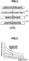
- Fig. 3 shows a predetermined desired driving force map based on hardware characteristics.
- Fig. 4 shows a predetermined characteristic map needed to set a desired transmission ratio.
- Fig. 5 is a flow chart showing transient-state desired values arithmetic-calculation routine executed within the control unit incorporated in the driving force control apparatus of the first embodiment.
- Figs. 6A and 6B show a characteristic curve representative of a driving-force change pattern needed to realize an ideal acceleration rate owing to a rise in a manipulated variable of an accelerator.
- Fig. 7 shows a look-up table (or a map) of the driving-force change pattern formulated for every vehicle speed V and for every accelerator manipulated variable Acc.
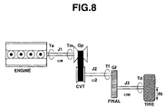
- Fig. 8 shows a power train having an engine and a continuously variable automatic transmission (CVT).
- CVT continuously variable automatic transmission
- Fig. 9 is a flow chart illustrating a routine needed to realize a desired engine torque and executed within the control unit incorporated in the driving force control apparatus of the first embodiment.
- Fig. 10 shows a predetermined desired engine torque versus desired intake-air quantity characteristic map.
- Fig. 11 shows a predetermined throttle opening Th/V map.
- Fig. 12 is a time chart showing variations in the driving force, obtained in the conventional driving force control apparatus that the engine torque and the transmission ratio are controlled independently of each other.
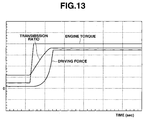
- Fig. 13 is a time chart showing variations in the driving force, obtained in the driving force control apparatus of the embodiment that the engine torque and the transmission ratio are tune-controlled.
- Fig. 14 shows a predetermined map for both a time rate of change ⁇ Te in engine torque and a time rate of change ⁇ Gp in transmission ratio, preset for every vehicle speed V and for every accelerator manipulated variable Acc, and used within the control unit of the driving force control apparatus of the third embodiment.
- the driving force control apparatus of the embodiment is exemplified in an automotive vehicle equipped with a power train having an internal combustion engine 1 and a continuously variable automatic transmission (often abbreviated to "CVT") 2 with a lock-up torque converter.
- Driving torque is transmitted from the power train through a propeller shaft 3, a rear differential 4, left and right axle driveshafts 5 and 6 to left and right rear drive wheels 7 and 8.
- engine 1 is equipped with a throttle actuator, fuel injector valves and spark plugs.
- the throttle actuator is responsive to a throttle-valve (Th/V) opening signal from an output interface 9e of an electronic control unit (ECU) 9 so as to control or adjust the throttle opening.
- Th/V throttle-valve
- the amount of fuel injected from each individual fuel injector valve is controlled by a fuel-injection amount signal from output interface 9e.
- a duty-cycle controlled pulse-width modulated signal is generally used as the fuel-injection amount signal.
- An ignition timing signal (or a pulse generator signal) for each spark plug is output from within output interface 9e so as to ignite air/fuel mixture within the combustion chamber in response to the ignition timing signal.
- CVT 2 is equipped with a lock-up actuator and a transmission-ratio actuator. The application and release of the lock-up clutch of the torque converter is controlled in response to a lock-up signal from output interface 9e.
- the transmission ratio actuator is provided to control the transmission ratio in response to the transmission ratio signal from output interface 9e, while varying the transmission ratio steplessly within limits.
- ECU 9 the throttle opening, fuel-injection amount, and ignition timing are controlled by means of ECU 9.
- the application and release of the torque converter lock-up clutch and the transmission ratio are also controlled by ECU 9.
- the ECU generally comprises a microcomputer.
- ECU 9 includes input and output interfaces 9a and 9e, memories (RAM denoted by 9c and ROM denoted by 9d), and a microprocessor or a central processing unit (CPU).
- Input interface 9a of ECU 9 receives input information from various engine/vehicle sensors, namely a crank angle sensor 10, an air-flow meter 11, an engine temperature sensor 12, a vehicle speed sensor 13, and an accelerator sensor 14.
- Crank angle sensor 10 is provided to inform the ECU of the engine speed N E .
- Air-flow meter 11 is provided to detect the quantity Q a of intake air drawn into the engine.
- Engine temperature sensor 12 is comprised of an engine coolant temperature sensor that detects a temperature of engine coolant.
- Vehicle speed sensor 13 is provided to detect vehicle speed V. Actually, a transmission output speed is monitored by vehicle speed sensor 13 and used as the vehicle speed.
- Accelerator sensor (ACC sensor) 14 is provided to detect a manipulated variable of the accelerator (an amount of depression of the accelerator pedal) and to generate an accelerator opening indicative signal (ACC sensor signal) Acc.
- Input interface 9a receives engine-speed indicative signal NE from the crank angle sensor, intake-air quantity indicative signal Q a from the air-flow meter, coolant temperature sensor signal T w from engine temperature sensor 12, vehicle speed sensor signal V from vehicle speed sensor 13, and accelerator opening indicative signal Acc from the ACC sensor.
- the central processing unit CPU
- CPU 9b of ECU 9 is responsible for carrying the steady-state desired values arithmetic-calculation program (see Fig. 2)/transient-state desired values arithmetic-calculation program (see Fig.
- Computational results that is, calculated output signals (solenoid drive currents) are relayed via output interface 9e of the ECU to output stages, namely the throttle actuator included in the engine output control system, fuel injector solenoids constructing part of the electronic fuel injection system, spark plugs constructing part of the electronic ignition system, and electromagnetic solenoid valves constructing part of a hydraulic modulator for lock-up control/transmission ratio control purposes.
- steady-state desired values (a steady-state desired engine torque and a steady-state desired transmission ratio) arithmetic-calculation routine executed within the CPU of ECU 9.
- a static desired driving force or a steady-state desired driving force is arithmetically calculated or computed on the basis of accelerator manipulated variable Acc from ACC sensor 14 and vehicle speed V from vehicle speed sensor 13.
- the static desired driving force is map-retrieved based on accelerator manipulated variable Acc and vehicle speed V from the preprogrammed or predetermined desired driving force map of Fig. 3 showing how the desired driving force has to be varied relative to both accelerator manipulated variable Acc and vehicle speed V.
- the desired driving force characteristic is predetermined by both the vehicle speed V and accelerator manipulated variable Acc, for the reasons set out below. This is because an engine torque characteristic of engine 1 and a transmission ratio characteristic of CVT 2 are determined depending upon both the vehicle speed and accelerator manipulated variable, and also the desired driving force characteristic can be determined as the product of the engine torque characteristic and the transmission ratio characteristic.
- the steady-state desired engine torque value is arithmetically calculated or computed based on the desired driving force obtained through step S30.
- the actual transmission ratio is a ratio (N E /V) of the engine speed N E (equal to the transmission input speed) to the vehicle speed V (equal to the transmission output speed).
- the steady-state desired transmission ratio is arithmetically calculated or computed on the basis of accelerator manipulated variable Acc and vehicle speed V.
- the desired transmission input speed is first map-retrieved based on accelerator manipulated variable Acc and vehicle speed V from the preprogrammed or predetermined characteristic map of Fig. 4 showing how the desired transmission input speed has to be varied relative to both accelerator manipulated variable Acc and vehicle speed V.
- transient-state desired values (a transient-state desired engine torque and a transient-state desired transmission ratio) arithmetic-calculation routine executed within the CPU of ECU 9.
- a desired driving-force change pattern is arithmetically calculated or computed based on the static desired driving force calculated through step S30 of Fig. 2.
- the desired driving-force change pattern is hereunder described in detail in reference to the driving-force characteristic curve of Fig. 6B showing how a driving force has to be varied intendedly with the lapse of time with the accelerator manipulated variable Acc risen at a time point t0 (see Fig. 6A). As can be seen in Figs.
- the driving-force response characteristic curve is classified into at least four different portions or time periods, namely (1) a leading edge portion a(t), (2) an initial response portion b(t), (3) a maximum change portion c(t), and (4) a peak portion d(t).
- An ideal driving-force change pattern (or an ideal driving-force response characteristic) is different for each of the four different portions a(t), b(t), c(t), and d(t).
- each of the portions a(t), b(t), c(t), and d(t) requires the following points or features. That is, leading edge portion a(t) corresponding to the first time period (t1-t0) between t0 and t1 requires a smoothness (a smooth driving-force change).
- Initial response portion b(t) corresponding to the second time period (t2-t1) between t1 and t2 requires a rapidity (a rapid driving-force change).
- Maximum change portion c(t) corresponding to the third time period (t3-t2) between t2 and t3 requires a great magnitude (a great driving-force change).
- Peak portion d(t) corresponding to the fourth time period (t4-t3) between t3 and t4 requires a proper time of arrival (a properly timed arrival to the peak point) as well as a great magnitude (a great driving-force change).
- the ideal desired driving-force change pattern containing four portions a(t), b(t), c(t), and d(t) is predetermined or preprogrammed depending on the type of vehicle, the concept of vehicle, the size of engine the vehicles use, and the like (see Fig. 6B).
- Fig. 7 shows an example of the preprogrammed look-up table for required values which are formulated depending on both the accelerator manipulated variable Acc and the initial vehicle speed.
- the transient-state desired engine torque value is arithmetically calculated or computed based on the desired driving-force change pattern formulated (see the look-up table of Fig. 7).
- the accelerator manipulated variable Acc is 10 [degree]
- the accelerator is operated in a stepwise manner at t0 and thus accelerator manipulated variable Acc is risen stepwise at t0
- the transient-state desired engine torque value Td(t) is determined for each time point (t1, t2, t3, t4) as follows.
- the transient-state desired transmission ratio is arithmetically calculated or computed based on the desired driving-force change pattern formulated and computed at step S60 (see the look-up table of Fig. 7).
- the transient-state desired transmission ratio is calculated as follows. First of all, accelerator manipulated variable Acc is calculated or map-retrieved based on each of the desired driving forces a(t), b(t), ... d(t) calculated at step S60 and vehicle speed V from the preprogrammed characteristic map shown in Fig. 3.
- the desired transmission input speed is calculated or map-retrieved based on the accelerator manipulated variable Acc retrieved and vehicle speed V from the preprogrammed characteristic map shown in Fig. 4.
- the transient-state desired transmission ratio is obtained or determined by dividing the desired transmission input speed by the vehicle speed (the transmission output speed).
- equations of motion for every part of a simplified power-train model shown in Fig. 8, comprised of an engine, a CVT, a final gear, and a drive wheel are considered or analyzed as follows.
- basic equations of motion about each of shafts, namely a CVT input shaft, a CVT output shaft, and an axle driveshaft are represented by the following equations (1) - (6).
- T e -T m J1 ⁇ (d ⁇ e /dt)
- G p ⁇ T m -T f J2 ⁇ (d ⁇ 2 /dt)
- G f ⁇ T f -T d J3 ⁇ (d ⁇ w /dt)
- J1 denotes the moment of inertia (simply, the inertia) of the engine and the CVT input shaft
- Te denotes engine torque
- ⁇ e denotes engine speed (i.e., an angular velocity of the CVT input shaft)
- Tm denotes CVT input torque
- J2 denotes the moment of inertia (simply, the inertia) of the CVT output shaft between the output side of the CVT and the input side of the final gear
- G p
- T d G f ⁇ G p ⁇ T e -G f 2 ⁇ G p ⁇ J1 ⁇ w ⁇ (dG p /dt) -(G f 2 ⁇ G p 2 ⁇ J1+G f 2 ⁇ J2+J3) ⁇ (d ⁇ w /dt)
- a first term Gf ⁇ Gp ⁇ Te of the expression (8) corresponds to a driving torque produced by the engine torque
- a second term Gf 2 ⁇ Gp ⁇ J1 ⁇ ⁇ w ⁇ (dGp/dt) corresponds to an inertia torque occurring due to a change in the transmission ratio of the CVT
- a third term (G f 2 ⁇ G p 2 ⁇ J1+G f 2 ⁇ J2+J3) ⁇ (d ⁇ w /dt) corresponds
- the third term (G f 2 ⁇ G p 2 ⁇ J1+G f 2 ⁇ J2+J3) ⁇ (d ⁇ w /dt) corresponding to an inertia torque occurring due to a change in vehicle speed, is negligible, because the change in vehicle velocity tends to be less than the other factors, namely a change in the transmission ratio and a change in the engine torque. Therefore, the driving torque Td can be more simply rewritten by the following expression (9) by eliminating the third term.
- T d G f ⁇ G p ⁇ T e -G f 2 ⁇ G p ⁇ J1 ⁇ ⁇ w ⁇ (dG p /dt) It is desirable to determine the desired engine torque and the desired transmission ratio so that the driving torque Td obtained by the above expression (9) is identical to the required driving force (or the desired driving force formulated) classified by conditions, that is, the accelerator manipulated variable and the initial vehicle speed (see the table of Fig. 7). However, it is difficult to derive both the desired engine torque and the desired transmission ratio from only one driving-force equation.
- the curvature is represented as T d "/ ⁇ 1+(T d ') 2 ⁇ 3/2 .
- the solution of the driving-force equations (7), (8) or (9) for the desired engine torque and the desired transmission ratio may be pre-calculated offline, so that the driving force Td defined by the driving-force equations (7), (8), or (9) is identical to the required driving force classified by the previously-noted conditions shown in Fig. 7.
- Fig. 9 there is shown the engine torque control routine needed to realize the desired engine torque.
- this routine of Fig. 9 is executed as time-triggered interrupt routines to be triggered every predetermined time intervals.
- a desired engine torque is calculated by solving the differential equations (10) and (11) in such a manner as to match the time rate of change in the required driving force classified by the previously-noted conditions and the curvature in the required driving force classified by the previously-noted conditions.
- a desired intake-air quantity is calculated based on the desired engine torque.
- the desired intake-air quantity is map-retrieved based on both the desired engine torque and the actual engine speed from a predetermined or preprogrammed characteristic map of Fig. 10 showing how the desired intake-air quantity has to be varied relative to both the desired engine torque and the actual engine speed.
- a desired throttle-valve opening (desired Th/V opening) is calculated based on the desired intake-air quantity.
- the desired throttle opening is map-retrieved based on the desired intake-air quantity and the actual engine speed from a predetermined or preprogrammed characteristic map of Fig. 11 showing how the desired throttle opening has to be varied relative to both the actual engine speed and the desired intake-air quantity.
- the throttle-valve opening signal corresponding to the desired throttle opening is output from a throttle-valve actuator control section of ECU 9 via the output interface to the throttle actuator, so as to set the throttle valve at the desired throttle opening obtained through step S112.
- the throttle-valve actuator control section is included in a desired engine torque realization section (or a desired engine torque realization means). Therefore, the desired engine torque can be realized by way of the intake-air quantity control that ensures a smooth engine torque change without deteriorating the driveability (without the undesirable torque difference).
- a desired transmission ratio is also calculated by solving the differential equations (10) and (11) in such a manner as to match the time rate of change in the required driving force classified by the previously-noted conditions and the curvature in the required driving force classified by the previously-noted conditions.
- the transmission ratio signal corresponding to the desired transmission ratio is output from a transmission-ratio actuator control section of ECU 9 via the output interface to the transmission ratio actuator, so that the actual transmission ratio is brought closer to the desired transmission ratio, by setting the actual transmission ratio at the desired transmission ratio.
- the transmission-ratio actuator control section is included in a desired transmission ratio realization section (or a desired transmission ratio realization means). Therefore, the desired transmission ratio can be realized by way of the transmission ratio control that ensures a smooth transmission ratio change without deteriorating the driveability (without the undesirable torque difference).
- the desired engine torque (Te) and the desired transmission ratio (Gp) are computed or derived in real time from the expressions (9), (10), and (11), on the basis of the desired driving-force change pattern of Fig. 7 (the desired driving-force characteristic curve of Fig. 6B), which pattern is predetermined depending on the type of the vehicle, the concept of the vehicle and the like.
- Engine 1 and CVT 2 are simultaneously controlled based on the desired engine torque (Te) calculated and desired transmission ratio (Gp) calculated. That is, in the driving force control apparatus of the embodiment, the engine torque and the transmission ratio are both tune-controlled such that engine torque control and transmission ratio control progress simultaneously smoothly, as shown in Fig. 13.
- the desired driving-force change pattern that is, the smooth and rapid response characteristic for the driving torque can be ensured.
- the driving force can be risen up smoothly rapidly (see the smoothly risen driving-force characteristic curve of Fig. 13).
- the driving force control apparatus based on the independent control exhibits a driving-force characteristic that the driving force greatly drops owing to the inertia torque component occurring due to the change in the transmission ratio of the CVT. As a result, it is impossible to realize a smooth rise in the driving force, thus deteriorating the vehicle driveability.
- the driving force control apparatus of the first embodiment includes a desired driving force calculation section (or a desired driving force calculation means) that calculates a static desired driving force based on both the accelerator manipulated variable Acc and vehicle speed V, a desired driving-force change pattern calculation section (or a desired driving-force change pattern calculation means) that calculates, based on the static desired driving force, a desired driving-force change pattern defined by a time rate of change in the desired driving force and a curvature of the desired driving force, a steady-state desired value calculation section (or a steady-state desired value calculation means) that calculates a steady-state desired engine torque value based on the static desired driving force and calculates a steady-state desired transmission ratio based on both the accelerator manipulated variable Acc and vehicle speed V, a transient-state desired value calculation section (or a transient-state desired value calculation means) that calculates a transient-state desired engine torque value and a transient-state desired transmission ratio, using predetermined physical expressions (predetermined equations of motion)
- the driving force control apparatus of the embodiment is suitable to various transient vehicle's acceleration patterns. That is, in the control apparatus of the first embodiment, the driving-force response characteristic, the smoothness of the driving-force characteristic curve, and the magnitude of the acceleration rate can be smoothly optimally controlled even in a transient accelerating state. This greatly improves the vehicle driveability (containing the acceleration performance) and engine power output. In other words, the driver-required driving torque (i.e., the driver-required or driver's intended acceleration rate) can be realized even during initial acceleration, thus enhancing the acceleration feeling.
- the driver-required driving torque i.e., the driver-required or driver's intended acceleration rate
- a final desired engine torque (Te) is computed, determined or derived from both the steady-state desired engine torque value calculated through step S31 and the transient-state desired engine torque value calculated through step S61, while a final desired transmission ratio (Gp) is computed, determined or derived from both the steady-state desired transmission ratio calculated through step S32 and the transient-state desired transmission ratio calculated through step S62.
- engine 1 and CVT 2 are tune-controlled based on the final desired engine torque (Te) and the final desired transmission ratio (Gp).
- the steady-state desired engine torque value calculated through step S31 of Fig. 2 and the transient-state desired engine torque value calculated through step S61 of Fig. 5 are both used to finally determine the desired engine torque (Te), based on the desired driving-force change pattern of Fig. 7.
- the control apparatus of the second embodiment can provide the same effects and operation as the first embodiment.
- the transient-state desired value (the transient-state desired engine torque value or the transient-state desired transmission ratio) is set as an absolute value
- the transient-state desired value may be used in lieu of the steady-state desired value.
- a driving force control apparatus of the third embodiment on the assumption that the computing capacity of the CPU of ECU 9 is insufficient, the solution of the driving-force equations (7), (8) or (9) for the desired engine torque and the desired transmission ratio is pre-calculated offline and additionally a time rate of change ⁇ Te in engine torque and a time rate of change ⁇ Gp in transmission ratio are preset as map data and classified by conditions, namely the accelerator manipulated variable and the initial vehicle speed (see Fig. 14).
- the solution of the driving-force equations (7), (8) or (9) for the desired engine torque and the desired transmission ratio is pre-calculated offline, so that the driving force Td defined by the driving-force equations (7), (8), or (9) is identical to the required driving force classified by the previously-noted conditions shown in Fig. 7.
- a time rate of change ⁇ Te in engine torque and a time rate of change ⁇ Gp in transmission ratio are preset as map data, for every conditions.
- the desired engine torque (Te) and the desired transmission ratio (Gp) are derived or computed.
- Engine 1 and CVT 2 are controlled based on the desired engine torque (Te) and desired transmission ratio (Gp) computed.
- the control apparatus of the third embodiment can provide the same effects and operation as the first embodiment.
- the driving force control apparatus of the embodiments has a control specification that a transient-state desired value for the driving force as well as a steady-state desired value for the driving force can be achieved or realized by way of tune-control for both the engine torque and the transmission ratio, thus ensuring a good transient acceleration feeling in particular during the early stages of the vehicle acceleration.
- a change pattern for the driving force with respect to time t is formulated and classified by predetermined conditions, namely the accelerator manipulated variable Acc and vehicle speed V (see Figs. 6B and 7). Therefore, there is an increased tendency for the desired driving force to change smoothly in the positive time-axis direction. This enhances or improves the acceleration performance and vehicle driveability.
- the driving force (or the driving torque) is formulated, taking into account all of the engine torque, the transmission ratio, the inertia torque occurring due to the change in the transmission ratio, and the inertia torque occurring due to the change in vehicle speed (or due to the change in drive wheel speed).
- the previously change pattern for the driving force is defined based on both the rate of change in the driving force with respect to time t and the curvature of the driving force with respect to time t. Equations of motion for the driving force (or the driving torque), and differential equations for a change in the driving force (or the driving torque) are utilized.
- the equations of motion (containing the differential equations) are solved so that the change pattern for the driving force is identical to the desired driving-force change pattern that provides the desired acceleration performance and vehicle driveability.
Abstract
Description
- The present invention relates to a driving force control apparatus suitable to a vehicle equipped with a power train having an engine and a transmission.
- Driving force control apparatus have been disclosed in Japanese Patent Provisional Publication Nos. 62-199536 (hereinafter is referred to as "JP62-199536"), 2000-45811 (hereinafter is referred to as "JP2000-45811"), and 11-255002 (hereinafter is referred to as "JP11-255002").
- In a control method for a vehicle driving system disclosed in JP62-199536, a desired driving torque is determined depending upon a manipulated variable of an accelerator and vehicle speed. A desired transmission ratio and a desired engine torque value are computed based on the desired driving force to produce an optimal engine operating point for good fuel economy. JP2000-45811 teaches the compensation for a deviation of an actual driving force from a desired value (a desired driving force), arising from inertia torque occurring owing to a delay in shifting of an automatic transmission and a change in wheel speed. The deviation from the desired driving force is compensated for by correcting engine torque. In a driving force controller disclosed in JP11-255002, when a change in a first factor of two factors, namely a transmission ratio and an engine torque output, is time-delayed as compared to a change in the second factor, in other words, when a time delay in a control system for the first factor is greater than a time delay in a control system for the second factor, an excess or deficiency of the driving force, occurring due to the time delay in the control system for the first factor, is compensated for by temporarily varying or adjusting the change in the second factor for the control system having a comparatively less time delay.
- In each control specification of driving force control systems disclosed in the JP62-199536, JP2000-45811 and JP11-255002, the deviation from the desired driving force, arising from the inertia torque occurring owing to a delay in automatic transmission shifting and a rotational-speed change (such as a wheel-speed change), is compensated for by way of engine torque control. Thus, these control systems have the difficulty in accurately realizing the driver-required driving force. In presence of an excessive engine-torque requirement greater than an engine torque value at full throttle, it is difficult to realize a desired driving force. Also, the previously-discussed control systems do not take full account of realization of a transient torque value. In particular, depending on how a transient torque is produced during early stages of vehicle acceleration, there is a possibility of a lack in acceleration feeling and undesired noises/vibrations, that is, a deterioration in vehicle driveability.
- Accordingly, it is an object of the invention to provide a driving force control apparatus, which avoids the aforementioned disadvantages.
- It is another object of the invention to provide a driving force control apparatus, which is capable of providing an improved control specification that realizes a transient-state desired value for the driving force as well as a steady-state desired value for the driving force by way of tune control for both a transmission ratio and an engine torque value, so as to realize a driver-required driving torque and improve the vehicle driveability (containing the acceleration performance) and engine power output.
- In order to accomplish the aforementioned and other objects of the present invention, a driving force control apparatus for an automotive vehicle equipped with a power train having an engine and a transmission, comprises sensors detecting at least a manipulated variable of an accelerator and a vehicle speed, a desired driving force calculation section that calculates a static desired driving force based on both the manipulated variable and the vehicle speed, a driving-force change pattern calculation section that calculates a desired driving-force change pattern based on the static desired driving force, a steady-state desired value calculation section that calculates a steady-state desired engine torque value based on the static desired driving force and calculates a steady-state desired transmission ratio based on both the manipulated variable of the accelerator and the vehicle speed, a transient-state desired value calculation section that calculates a transient-state desired engine torque value and a transient-state transmission ratio, based on the desired driving-force change pattern, and an engine-torque and transmission-ratio tune-control section capable of simultaneously progressing both engine torque control for the steady-state desired engine torque value and the transient-state desired engine torque value and transmission ratio control for the steady-state desired transmission ratio and the transient-state desired transmission ratio.
- According to another aspect of the invention, a driving force control apparatus for an automotive vehicle equipped with a power train having an engine and a transmission, comprises a first sensor detecting a manipulated variable of an accelerator, a second sensor detecting a vehicle speed, a desired driving force calculation section that calculates a static desired driving force based on both the manipulated variable and the vehicle speed, a driving-force change pattern calculation section that calculates a desired driving-force change pattern based on the static desired driving force, a steady-state desired value calculation section that calculates a steady-state desired engine torque value based on the static desired driving force and also calculates a steady-state desired transmission ratio based on both the manipulated variable of the accelerator and the vehicle speed, a transient-state desired value calculation section that calculates a transient-state desired engine torque value and a transient-state transmission ratio, based on the desired driving-force change pattern, a desired engine torque realization section that realizes the transient-state desired engine torque value as well as the steady-state desired engine torque value, and a desired transmission ratio realization section that realizes the transient-state desired transmission ratio as well as the steady-state desired transmission ratio.
- The other objects and features of this invention will become understood from the following description with reference to the accompanying drawings.
- Fig. 1 is a system block diagram illustrating a first embodiment of a driving force control apparatus.
- Fig. 2 is a flow chart showing steady-state desired values arithmetic-calculation routine executed within a control unit incorporated in the driving force control apparatus of the first embodiment.
- Fig. 3 shows a predetermined desired driving force map based on hardware characteristics.
- Fig. 4 shows a predetermined characteristic map needed to set a desired transmission ratio.
- Fig. 5 is a flow chart showing transient-state desired values arithmetic-calculation routine executed within the control unit incorporated in the driving force control apparatus of the first embodiment.
- Figs. 6A and 6B show a characteristic curve representative of a driving-force change pattern needed to realize an ideal acceleration rate owing to a rise in a manipulated variable of an accelerator.
- Fig. 7 shows a look-up table (or a map) of the driving-force change pattern formulated for every vehicle speed V and for every accelerator manipulated variable Acc.
- Fig. 8 shows a power train having an engine and a continuously variable automatic transmission (CVT).
- Fig. 9 is a flow chart illustrating a routine needed to realize a desired engine torque and executed within the control unit incorporated in the driving force control apparatus of the first embodiment.
- Fig. 10 shows a predetermined desired engine torque versus desired intake-air quantity characteristic map.
- Fig. 11 shows a predetermined throttle opening Th/V map.
- Fig. 12 is a time chart showing variations in the driving force, obtained in the conventional driving force control apparatus that the engine torque and the transmission ratio are controlled independently of each other.
- Fig. 13 is a time chart showing variations in the driving force, obtained in the driving force control apparatus of the embodiment that the engine torque and the transmission ratio are tune-controlled.
- Fig. 14 shows a predetermined map for both a time rate of change ΔTe in engine torque and a time rate of change ΔGp in transmission ratio, preset for every vehicle speed V and for every accelerator manipulated variable Acc, and used within the control unit of the driving force control apparatus of the third embodiment.
- Referring now to the drawings, particularly to Fig. 1, the driving force control apparatus of the embodiment is exemplified in an automotive vehicle equipped with a power train having an internal combustion engine 1 and a continuously variable automatic transmission (often abbreviated to "CVT") 2 with a lock-up torque converter. Driving torque is transmitted from the power train through a propeller shaft 3, a rear differential 4, left and right axle driveshafts 5 and 6 to left and right rear drive wheels 7 and 8. Although it is not clearly shown in Fig. 1, engine 1 is equipped with a throttle actuator, fuel injector valves and spark plugs. The throttle actuator is responsive to a throttle-valve (Th/V) opening signal from an output interface 9e of an electronic control unit (ECU) 9 so as to control or adjust the throttle opening. The amount of fuel injected from each individual fuel injector valve is controlled by a fuel-injection amount signal from output interface 9e. A duty-cycle controlled pulse-width modulated signal is generally used as the fuel-injection amount signal. An ignition timing signal (or a pulse generator signal) for each spark plug is output from within output interface 9e so as to ignite air/fuel mixture within the combustion chamber in response to the ignition timing signal. On the other hand, CVT 2 is equipped with a lock-up actuator and a transmission-ratio actuator. The application and release of the lock-up clutch of the torque converter is controlled in response to a lock-up signal from output interface 9e. The transmission ratio actuator is provided to control the transmission ratio in response to the transmission ratio signal from output interface 9e, while varying the transmission ratio steplessly within limits. As clearly shown in Fig. 1, the throttle opening, fuel-injection amount, and ignition timing are controlled by means of ECU 9. The application and release of the torque converter lock-up clutch and the transmission ratio are also controlled by ECU 9. The ECU generally comprises a microcomputer. ECU 9 includes input and output interfaces 9a and 9e, memories (RAM denoted by 9c and ROM denoted by 9d), and a microprocessor or a central processing unit (CPU). Input interface 9a of ECU 9 receives input information from various engine/vehicle sensors, namely a crank angle sensor 10, an air-flow meter 11, an engine temperature sensor 12, a vehicle speed sensor 13, and an accelerator sensor 14. Crank angle sensor 10 is provided to inform the ECU of the engine speed NE. Air-flow meter 11 is provided to detect the quantity Qa of intake air drawn into the engine. Engine temperature sensor 12 is comprised of an engine coolant temperature sensor that detects a temperature of engine coolant. Vehicle speed sensor 13 is provided to detect vehicle speed V. Actually, a transmission output speed is monitored by vehicle speed sensor 13 and used as the vehicle speed. Accelerator sensor (ACC sensor) 14 is provided to detect a manipulated variable of the accelerator (an amount of depression of the accelerator pedal) and to generate an accelerator opening indicative signal (ACC sensor signal) Acc. Input interface 9a receives engine-speed indicative signal NE from the crank angle sensor, intake-air quantity indicative signal Qa from the air-flow meter, coolant temperature sensor signal Tw from engine temperature sensor 12, vehicle speed sensor signal V from vehicle speed sensor 13, and accelerator opening indicative signal Acc from the ACC sensor. Within the ECU, the central processing unit (CPU) allows the access by the input interface of input informational data signals from the previously-discussed engine/vehicle sensors 10, 11, 12, 13, and 14. CPU 9b of ECU 9 is responsible for carrying the steady-state desired values arithmetic-calculation program (see Fig. 2)/transient-state desired values arithmetic-calculation program (see Fig. 5)/desired engine torque control program (desired engine torque/desired intake-air quantity/desired throttle opening arithmetic-calculation program)(see Fig. 9)/electronic fuel-injection control program/electronic ignition-timing control program/transmission torque converter lock-up control program/transmission ratio control program stored in memories and is capable of performing necessary arithmetic and logic operations shown in Figs. 2, 5 and 9. Computational results (arithmetic calculation results), that is, calculated output signals (solenoid drive currents) are relayed via output interface 9e of the ECU to output stages, namely the throttle actuator included in the engine output control system, fuel injector solenoids constructing part of the electronic fuel injection system, spark plugs constructing part of the electronic ignition system, and electromagnetic solenoid valves constructing part of a hydraulic modulator for lock-up control/transmission ratio control purposes.
- Referring now to Fig. 2, there is shown the steady-state desired values (a steady-state desired engine torque and a steady-state desired transmission ratio) arithmetic-calculation routine executed within the CPU of ECU 9.
- At step S30, a static desired driving force or a steady-state desired driving force is arithmetically calculated or computed on the basis of accelerator manipulated variable Acc from ACC sensor 14 and vehicle speed V from vehicle speed sensor 13. Actually, the static desired driving force is map-retrieved based on accelerator manipulated variable Acc and vehicle speed V from the preprogrammed or predetermined desired driving force map of Fig. 3 showing how the desired driving force has to be varied relative to both accelerator manipulated variable Acc and vehicle speed V. As appreciated from the desired driving force characteristic shown in Fig. 3, in the system of the shown embodiment, the desired driving force characteristic is predetermined by both the vehicle speed V and accelerator manipulated variable Acc, for the reasons set out below. This is because an engine torque characteristic of engine 1 and a transmission ratio characteristic of CVT 2 are determined depending upon both the vehicle speed and accelerator manipulated variable, and also the desired driving force characteristic can be determined as the product of the engine torque characteristic and the transmission ratio characteristic.
- At step S31, the steady-state desired engine torque value is arithmetically calculated or computed based on the desired driving force obtained through step S30. Concretely, the steady-state desired engine torque value is calculated as a ratio of the desired driving force (retrieved from the preprogrammed desired driving force map of Fig. 3) to the actual transmission ratio. That is, the steady-state desired engine torque value is obtained by dividing the desired driving force by the actual transmission ratio (see the following equation).
- At step S32, the steady-state desired transmission ratio is arithmetically calculated or computed on the basis of accelerator manipulated variable Acc and vehicle speed V. Concretely, the desired transmission input speed is first map-retrieved based on accelerator manipulated variable Acc and vehicle speed V from the preprogrammed or predetermined characteristic map of Fig. 4 showing how the desired transmission input speed has to be varied relative to both accelerator manipulated variable Acc and vehicle speed V. Thereafter, the steady-state desired transmission ratio is computed as a ratio of the desired transmission input speed to the vehicle speed (i.e., transmission output speed), that is, (steady-state desired transmission ratio)=(desired transmission input speed)/(vehicle speed).
- Referring now to Fig. 5, there is shown the transient-state desired values (a transient-state desired engine torque and a transient-state desired transmission ratio) arithmetic-calculation routine executed within the CPU of ECU 9.
- At step S60, a desired driving-force change pattern is arithmetically calculated or computed based on the static desired driving force calculated through step S30 of Fig. 2. The desired driving-force change pattern is hereunder described in detail in reference to the driving-force characteristic curve of Fig. 6B showing how a driving force has to be varied intendedly with the lapse of time with the accelerator manipulated variable Acc risen at a time point t0 (see Fig. 6A). As can be seen in Figs. 6A and 6B, there is a difference in estimation of driver's acceleration feeling, owing to the time rate of change in acceleration (that is, the jerk) based on the driver's accelerator operation or the driver's accelerator pedal depression, in other words, owing to the time rate of change in the driving force. When finely and accurately analyzing variations or changes in the driving force (a response characteristic of the driving force) just after operation of the accelerator, the driving-force response characteristic curve is classified into at least four different portions or time periods, namely (1) a leading edge portion a(t), (2) an initial response portion b(t), (3) a maximum change portion c(t), and (4) a peak portion d(t). An ideal driving-force change pattern (or an ideal driving-force response characteristic) is different for each of the four different portions a(t), b(t), c(t), and d(t). In order to enhance the estimation of driver's acceleration feeling, each of the portions a(t), b(t), c(t), and d(t) requires the following points or features. That is, leading edge portion a(t) corresponding to the first time period (t1-t0) between t0 and t1 requires a smoothness (a smooth driving-force change). Initial response portion b(t) corresponding to the second time period (t2-t1) between t1 and t2 requires a rapidity (a rapid driving-force change). Maximum change portion c(t) corresponding to the third time period (t3-t2) between t2 and t3 requires a great magnitude (a great driving-force change). Peak portion d(t) corresponding to the fourth time period (t4-t3) between t3 and t4 requires a proper time of arrival (a properly timed arrival to the peak point) as well as a great magnitude (a great driving-force change). For the reasons set forth above, the ideal desired driving-force change pattern containing four portions a(t), b(t), c(t), and d(t) is predetermined or preprogrammed depending on the type of vehicle, the concept of vehicle, the size of engine the vehicles use, and the like (see Fig. 6B). Actually, for every vehicle speed V and for every accelerator manipulated variable Acc, required values for these desired driving-force change pattern are determined. Fig. 7 shows an example of the preprogrammed look-up table for required values which are formulated depending on both the accelerator manipulated variable Acc and the initial vehicle speed.
- At step S61, the transient-state desired engine torque value is arithmetically calculated or computed based on the desired driving-force change pattern formulated (see the look-up table of Fig. 7). Concretely, the transient-state desired engine torque value is calculated as a ratio of the desired driving force (retrieved from the preprogrammed look-up table of Fig. 7) to the actual transmission ratio. That is, the transient-state desired engine torque value is obtained by dividing the desired driving force formulated by the actual transmission ratio, that is, (transient-state desired engine torque value)=(desired driving force formulated)/(actual transmission ratio). For instance, as shown in Figs. 6A and 6B, when the initial vehicle speed is 0[km/h], the accelerator manipulated variable Acc is 10 [degree], the accelerator is operated in a stepwise manner at t0 and thus accelerator manipulated variable Acc is risen stepwise at t0, the transient-state desired engine torque value Td(t) is determined for each time point (t1, t2, t3, t4) as follows.
- (i) Regarding leading edge portion a(t), the transient-state desired engine torque value Td(t1) is equal to a(t1)/(actual transmission ratio), since the desired driving force formulated is given as a(t1).
- (ii) Regarding initial response portion b(t), the transient-state desired engine torque value Td(t2) is equal to b(t2)/(actual transmission ratio), since the desired driving force formulated is given as b(t2).
- (iii) Regarding maximum change portion c(t), the transient-state desired engine torque value Td(t3) is equal to c(t3)/(actual transmission ratio), since the desired driving force formulated is given as c(t3).
- (iv) Regarding peak portion d(t), the transient-state desired engine torque value Td(t4) is equal to d(t4)/(actual transmission ratio), since the desired driving force formulated is given as d(t4).
-
- At step S62, the transient-state desired transmission ratio is arithmetically calculated or computed based on the desired driving-force change pattern formulated and computed at step S60 (see the look-up table of Fig. 7). Concretely, the transient-state desired transmission ratio is calculated as follows. First of all, accelerator manipulated variable Acc is calculated or map-retrieved based on each of the desired driving forces a(t), b(t), ... d(t) calculated at step S60 and vehicle speed V from the preprogrammed characteristic map shown in Fig. 3. Secondly, the desired transmission input speed is calculated or map-retrieved based on the accelerator manipulated variable Acc retrieved and vehicle speed V from the preprogrammed characteristic map shown in Fig. 4. Thirdly, the transient-state desired transmission ratio is obtained or determined by dividing the desired transmission input speed by the vehicle speed (the transmission output speed).
- In calculating desired values from a required driving force, equations of motion for every part of a simplified power-train model shown in Fig. 8, comprised of an engine, a CVT, a final gear, and a drive wheel are considered or analyzed as follows.
First, basic equations of motion about each of shafts, namely a CVT input shaft, a CVT output shaft, and an axle driveshaft are represented by the following equations (1) - (6).
From the aforementioned equations of motion (1) - (6) the driving torque Td can be represented by the following expressions (7) and (8).
- Hereinafter explained is a way to improve the response and smoothness for driving-force control characteristic. Of the first, second, and third terms of the above-mentioned expression (8), the third term (Gf 2·Gp 2·J1+Gf 2·J2+J3)·(dωw/dt) corresponding to an inertia torque occurring due to a change in vehicle speed, is negligible, because the change in vehicle velocity tends to be less than the other factors, namely a change in the transmission ratio and a change in the engine torque. Therefore, the driving torque Td can be more simply rewritten by the following expression (9) by eliminating the third term.
- Referring now to Fig. 9, there is shown the engine torque control routine needed to realize the desired engine torque. In the same manner as the other routines shown in Figs. 2 and 5, this routine of Fig. 9 is executed as time-triggered interrupt routines to be triggered every predetermined time intervals.
- At step S110, a desired engine torque is calculated by solving the differential equations (10) and (11) in such a manner as to match the time rate of change in the required driving force classified by the previously-noted conditions and the curvature in the required driving force classified by the previously-noted conditions.
- At step S111, a desired intake-air quantity is calculated based on the desired engine torque. Concretely, the desired intake-air quantity is map-retrieved based on both the desired engine torque and the actual engine speed from a predetermined or preprogrammed characteristic map of Fig. 10 showing how the desired intake-air quantity has to be varied relative to both the desired engine torque and the actual engine speed.
- At step S112, a desired throttle-valve opening (desired Th/V opening) is calculated based on the desired intake-air quantity. In order to realize the desired intake-air quantity, concretely, the desired throttle opening is map-retrieved based on the desired intake-air quantity and the actual engine speed from a predetermined or preprogrammed characteristic map of Fig. 11 showing how the desired throttle opening has to be varied relative to both the actual engine speed and the desired intake-air quantity. Thereafter, in order to realize the desired engine torque, the throttle-valve opening signal corresponding to the desired throttle opening is output from a throttle-valve actuator control section of ECU 9 via the output interface to the throttle actuator, so as to set the throttle valve at the desired throttle opening obtained through step S112. The throttle-valve actuator control section is included in a desired engine torque realization section (or a desired engine torque realization means). Therefore, the desired engine torque can be realized by way of the intake-air quantity control that ensures a smooth engine torque change without deteriorating the driveability (without the undesirable torque difference). Additionally, in a similar manner as discussed above, a desired transmission ratio is also calculated by solving the differential equations (10) and (11) in such a manner as to match the time rate of change in the required driving force classified by the previously-noted conditions and the curvature in the required driving force classified by the previously-noted conditions. As previously discussed, on the other hand, the actual transmission ratio is calculated as the ratio (NE/V) of the engine speed NE (= transmission input speed) to the vehicle speed V (= transmission output speed). Thereafter, in order to realize the desired transmission ratio, the transmission ratio signal corresponding to the desired transmission ratio is output from a transmission-ratio actuator control section of ECU 9 via the output interface to the transmission ratio actuator, so that the actual transmission ratio is brought closer to the desired transmission ratio, by setting the actual transmission ratio at the desired transmission ratio. The transmission-ratio actuator control section is included in a desired transmission ratio realization section (or a desired transmission ratio realization means). Therefore, the desired transmission ratio can be realized by way of the transmission ratio control that ensures a smooth transmission ratio change without deteriorating the driveability (without the undesirable torque difference).
- As discussed above, according to the driving force control apparatus of the embodiment, the desired engine torque (Te) and the desired transmission ratio (Gp) are computed or derived in real time from the expressions (9), (10), and (11), on the basis of the desired driving-force change pattern of Fig. 7 (the desired driving-force characteristic curve of Fig. 6B), which pattern is predetermined depending on the type of the vehicle, the concept of the vehicle and the like. Engine 1 and CVT 2 are simultaneously controlled based on the desired engine torque (Te) calculated and desired transmission ratio (Gp) calculated. That is, in the driving force control apparatus of the embodiment, the engine torque and the transmission ratio are both tune-controlled such that engine torque control and transmission ratio control progress simultaneously smoothly, as shown in Fig. 13. As can be appreciated from the time rate of change and the curvature of the lowermost smooth driving-force characteristic curve shown in Fig. 13, the desired driving-force change pattern, that is, the smooth and rapid response characteristic for the driving torque can be ensured. In other words, the driving force can be risen up smoothly rapidly (see the smoothly risen driving-force characteristic curve of Fig. 13).
- On the contrary, in case that engine 1 and CVT 2 are controlled independently of each other, as can be appreciated from the expression (8), in the presence of shifting, the inertia torque component occurring due to the change in the transmission ratio of the CVT (corresponding to the second term Gf2 · Gp · J1 · ωw · (dGp/dt)) tends to be subtracted from the driving torque component produced by the engine torque (corresponding to the first term Gf · Gp · Te). As a result, the response and smoothness of the driving-force control characteristic are prevented or deteriorated (see the polygonal-line driving-force characteristic shown in Fig. 12). As seen in Fig. 12, according to the independent control, the driving force rises up temporarily owing to a rise in engine torque. When the transmission ratio varies with a time delay from the timing when the engine torque starts to rise, the driving force control apparatus based on the independent control exhibits a driving-force characteristic that the driving force greatly drops owing to the inertia torque component occurring due to the change in the transmission ratio of the CVT. As a result, it is impossible to realize a smooth rise in the driving force, thus deteriorating the vehicle driveability.
- As set forth above, the driving force control apparatus of the first embodiment includes a desired driving force calculation section (or a desired driving force calculation means) that calculates a static desired driving force based on both the accelerator manipulated variable Acc and vehicle speed V, a desired driving-force change pattern calculation section (or a desired driving-force change pattern calculation means) that calculates, based on the static desired driving force, a desired driving-force change pattern defined by a time rate of change in the desired driving force and a curvature of the desired driving force, a steady-state desired value calculation section (or a steady-state desired value calculation means) that calculates a steady-state desired engine torque value based on the static desired driving force and calculates a steady-state desired transmission ratio based on both the accelerator manipulated variable Acc and vehicle speed V, a transient-state desired value calculation section (or a transient-state desired value calculation means) that calculates a transient-state desired engine torque value and a transient-state desired transmission ratio, using predetermined physical expressions (predetermined equations of motion) to satisfy the desired driving-force change pattern, and an engine-torque and transmission-ratio tune-control section capable of simultaneously progressing both engine torque control and transmission ratio control so as to realize the desired values, namely the steady-state desired engine torque value, the steady-state desired transmission ratio, the transient-state desired engine torque value, and the transient-state desired transmission ratio. For the reasons set out above, the driving force control apparatus of the embodiment is suitable to various transient vehicle's acceleration patterns. That is, in the control apparatus of the first embodiment, the driving-force response characteristic, the smoothness of the driving-force characteristic curve, and the magnitude of the acceleration rate can be smoothly optimally controlled even in a transient accelerating state. This greatly improves the vehicle driveability (containing the acceleration performance) and engine power output. In other words, the driver-required driving torque (i.e., the driver-required or driver's intended acceleration rate) can be realized even during initial acceleration, thus enhancing the acceleration feeling.
- In a driving force control apparatus of the second embodiment, on the basis of the desired driving-force change pattern of Fig. 7 predetermined depending on at least the type of the vehicle and the concept of the vehicle, a final desired engine torque (Te) is computed, determined or derived from both the steady-state desired engine torque value calculated through step S31 and the transient-state desired engine torque value calculated through step S61, while a final desired transmission ratio (Gp) is computed, determined or derived from both the steady-state desired transmission ratio calculated through step S32 and the transient-state desired transmission ratio calculated through step S62. Then, engine 1 and CVT 2 are tune-controlled based on the final desired engine torque (Te) and the final desired transmission ratio (Gp). That is, instead of using the previously-noted differential equations (10) and (11) in step S110, the steady-state desired engine torque value calculated through step S31 of Fig. 2 and the transient-state desired engine torque value calculated through step S61 of Fig. 5 are both used to finally determine the desired engine torque (Te), based on the desired driving-force change pattern of Fig. 7. The control apparatus of the second embodiment can provide the same effects and operation as the first embodiment. In case that the transient-state desired value (the transient-state desired engine torque value or the transient-state desired transmission ratio) is set as an absolute value, the transient-state desired value may be used in lieu of the steady-state desired value.
- In a driving force control apparatus of the third embodiment, on the assumption that the computing capacity of the CPU of ECU 9 is insufficient, the solution of the driving-force equations (7), (8) or (9) for the desired engine torque and the desired transmission ratio is pre-calculated offline and additionally a time rate of change ΔTe in engine torque and a time rate of change ΔGp in transmission ratio are preset as map data and classified by conditions, namely the accelerator manipulated variable and the initial vehicle speed (see Fig. 14). Taking into account the insufficient computing capacity of the CPU of ECU 9, the solution of the driving-force equations (7), (8) or (9) for the desired engine torque and the desired transmission ratio is pre-calculated offline, so that the driving force Td defined by the driving-force equations (7), (8), or (9) is identical to the required driving force classified by the previously-noted conditions shown in Fig. 7. On the other hand, as shown in Fig. 14, a time rate of change ΔTe in engine torque and a time rate of change ΔGp in transmission ratio are preset as map data, for every conditions. By way of map-retrieval from the predetermined or preprogrammed map of Fig. 14, the desired engine torque (Te) and the desired transmission ratio (Gp) are derived or computed. Engine 1 and CVT 2 are controlled based on the desired engine torque (Te) and desired transmission ratio (Gp) computed. The control apparatus of the third embodiment can provide the same effects and operation as the first embodiment.
- As will be appreciated from the above, in the driving force control apparatus of the embodiments, the deviation of the actual driving force from the desired value, resulting from inertia torque occurring owing to the delay in the automatic transmission shifting and a change in wheel speed, is not compensated for by only the engine torque control. In lieu thereof, the driving force control apparatus of the embodiment has a control specification that a transient-state desired value for the driving force as well as a steady-state desired value for the driving force can be achieved or realized by way of tune-control for both the engine torque and the transmission ratio, thus ensuring a good transient acceleration feeling in particular during the early stages of the vehicle acceleration. Furthermore, in order to provide the desired acceleration performance and the desired vehicle driveability, a change pattern for the driving force with respect to time t is formulated and classified by predetermined conditions, namely the accelerator manipulated variable Acc and vehicle speed V (see Figs. 6B and 7). Therefore, there is an increased tendency for the desired driving force to change smoothly in the positive time-axis direction. This enhances or improves the acceleration performance and vehicle driveability. Moreover, the driving force (or the driving torque) is formulated, taking into account all of the engine torque, the transmission ratio, the inertia torque occurring due to the change in the transmission ratio, and the inertia torque occurring due to the change in vehicle speed (or due to the change in drive wheel speed). The previously change pattern for the driving force is defined based on both the rate of change in the driving force with respect to time t and the curvature of the driving force with respect to time t. Equations of motion for the driving force (or the driving torque), and differential equations for a change in the driving force (or the driving torque) are utilized. The equations of motion (containing the differential equations) are solved so that the change pattern for the driving force is identical to the desired driving-force change pattern that provides the desired acceleration performance and vehicle driveability. Thus, it is possible to obtain a realistic or practical solution of the equations of motion for the engine torque and the transmission ratio, both needed to realize the driver-required driving force (in other words, the driver's intended acceleration rate).
- The entire contents of Japanese Patent Application No. P2000-281401 (filed September 18, 2000) is incorporated herein by reference.
- While the foregoing is a description of the preferred embodiments carried out the invention, it will be understood that the invention is not limited to the particular embodiments shown and described herein, but that various changes and modifications may be made without departing from the scope or spirit of this invention as defined by the following claims.
Claims (10)
- A driving force control apparatus for an automotive vehicle equipped with a power train having an engine and a transmission, comprising:sensors detecting at least a manipulated variable (Acc) of an accelerator and a vehicle speed (V);a desired driving force calculation section that calculates a static desired driving force based on both the manipulated variable (Acc) and the vehicle speed (V);a driving-force change pattern calculation section that calculates a desired driving-force change pattern based on the static desired driving force;a steady-state desired value calculation section that calculates a steady-state desired engine torque value based on the static desired driving force and calculates a steady-state desired transmission ratio based on both the manipulated variable (Acc) of the accelerator and the vehicle speed (V);a transient-state desired value calculation section that calculates a transient-state desired engine torque value and a transient-state transmission ratio, based on the desired driving-force change pattern; andan engine-torque and transmission-ratio tune-control section capable of simultaneously progressing both (a) engine torque control for the steady-state desired engine torque value and the transient-state desired engine torque value and (b) transmission ratio control for the steady-state desired transmission ratio and the transient-state desired transmission ratio.
- A driving force control apparatus for an automotive vehicle equipped with a power train having an engine and a transmission, comprising:a first sensor detecting a manipulated variable (Acc) of an accelerator;a second sensor detecting a vehicle speed (V);a desired driving force calculation section that calculates a static desired driving force based on both the manipulated variable (Acc) and the vehicle speed (V);a driving-force change pattern calculation section that calculates a desired driving-force change pattern based on the static desired driving force;a steady-state desired value calculation section that calculates a steady-state desired engine torque value based on the static desired driving force and calculates a steady-state desired transmission ratio based on both the manipulated variable (Acc) of the accelerator and the vehicle speed (V);a transient-state desired value calculation section that calculates a transient-state desired engine torque value and a transient-state transmission ratio, based on the desired driving-force change pattern;a desired engine torque realization section that realizes the transient-state desired engine torque value as well as the steady-state desired engine torque value; anda desired transmission ratio realization section that realizes the transient-state desired transmission ratio as well as the steady-state desired transmission ratio.
- The driving force control apparatus as claimed in claims 1 or 2, wherein the desired driving-force change pattern calculated by the driving-force change pattern calculation section is formulated as a change pattern for a desired driving force with respect to time (t), to provide a desired acceleration performance and a desired vehicle driveability.
- The driving force control apparatus as claimed in claim 3, wherein the desired driving-force change pattern is classified by predetermined conditions including at least the manipulated variable (Acc) of the accelerator and the vehicle speed (V).
- The driving force control apparatus as claimed in claims 1 or 2, wherein within the desired driving-force change pattern calculation section, a driving force is formulated taking into account at least an engine torque, a transmission ratio, an inertia torque occurring due to a change in the transmission ratio, and an inertia torque occurring due to a change in the vehicle speed, and a change pattern for the driving force is defined based on both a rate of change in the driving force with respect to time (t) and a curvature of the driving force with respect to time (t), and equations of motion for the driving force are solved so that the change pattern for the driving force is identical to the desired driving-force change pattern that provides a desired acceleration performance and a desired vehicle driveability.
- The driving force control apparatus as claimed in claims 2 through 5, wherein the desired engine torque realization section comprises:(1) a desired intake-air quantity calculation section calculating a desired intake-air quantity based on a desired engine torque corresponding to either the steady-state desired engine torque value or the transient-state desired engine torque value;(2) a desired throttle-valve opening calculation section calculating a desired throttle opening of a throttle valve based on the desired intake-air quantity; and(3) a throttle-valve actuator control section setting the throttle valve at the desired throttle opening.
- The driving force control apparatus as claimed in claims 2 through 6, wherein the transmission comprises a continuously variable automatic transmission whose transmission ratio is variable steplessly, and wherein the desired transmission ratio realization section comprises:(1) an actual transmission ratio calculation section calculating an actual transmission ratio as a ratio of a transmission input speed to a transmission output speed; and(2) a transmission-ratio actuator control section setting the actual transmission ratio at a desired transmission ratio corresponding to either the steady-state desired transmission ratio or the transient-state desired transmission ratio, so that the actual transmission ratio is brought closer to the desired transmission ratio.
- The driving force control apparatus as claimed in claim 5, wherein one of the equations of motion for the driving force is defined as follows:
- The driving force control apparatus as claimed in claim 5, wherein one of the equations of motion for the driving force is defined as follows:
- The driving force control apparatus as claimed in claim 9, wherein the transient-state desired engine torque value and the transient-state desired transmission ratio are obtained by solving the following two differential equations in such a manner as to match a time rate of change in a required driving force classified by predetermined conditions including at least the manipulated variable (Acc) of the accelerator and the vehicle speed (V) and a curvature of the required driving force, one of the two differential equations corresponding to a differential equation Td' of first order for the equation of motion Td = Gf · Gp · Te-Gf2 · Gp · J1 · ωw · (dGp/dt) and the other corresponding to a differential equation Td" of second order for the equation of motion Td = Gf · Gp · Te-Gf2 · Gp · J1 · ωw · (dGp/dt), and the time rate of change in the required driving force being related to the first-order differential equation dTd/dt (=Td'), the curvature of the required driving force being related to both the first-order differential equation dTd/dt (=Td') and the second-order differential equation d2Td/dt2 (=Td"), and the curvature being represented as Td"/{1+(Td')2}3/2:
Applications Claiming Priority (2)
| Application Number | Priority Date | Filing Date | Title |
|---|---|---|---|
| JP2000281401A JP3791315B2 (en) | 2000-09-18 | 2000-09-18 | Driving force control device |
| JP2000281401 | 2000-09-18 |
Publications (3)
| Publication Number | Publication Date |
|---|---|
| EP1188602A2 true EP1188602A2 (en) | 2002-03-20 |
| EP1188602A3 EP1188602A3 (en) | 2004-08-25 |
| EP1188602B1 EP1188602B1 (en) | 2006-03-29 |
Family
ID=18766064
Family Applications (1)
| Application Number | Title | Priority Date | Filing Date |
|---|---|---|---|
| EP01122128A Expired - Lifetime EP1188602B1 (en) | 2000-09-18 | 2001-09-14 | Driving force control apparatus |
Country Status (3)
| Country | Link |
|---|---|
| EP (1) | EP1188602B1 (en) |
| JP (1) | JP3791315B2 (en) |
| DE (1) | DE60118283T2 (en) |
Cited By (12)
| Publication number | Priority date | Publication date | Assignee | Title |
|---|---|---|---|---|
| EP1429011A1 (en) * | 2002-12-13 | 2004-06-16 | Renault S.A. | Engine torque control method and system for an automotive vehicle |
| US7949451B2 (en) | 2005-10-21 | 2011-05-24 | Toyota Jidosha Kabushiki Kaisha | Driving force control device of vehicle |
| CN102343908A (en) * | 2010-07-29 | 2012-02-08 | 三菱自动车工业株式会社 | Controlling device of hybrid power vehicle |
| US9079574B2 (en) | 2004-09-09 | 2015-07-14 | Torotrak (Development) Limited | Method for controlling a motor vehicle powertrain |
| JP2018140690A (en) * | 2017-02-27 | 2018-09-13 | 学校法人 中央大学 | Acceleration feeling estimation method and acceleration feeling estimation device |
| US11125329B2 (en) | 2007-11-16 | 2021-09-21 | Fallbrook Intellectual Property Company Llc | Controller for variable transmission |
| US11174922B2 (en) | 2019-02-26 | 2021-11-16 | Fallbrook Intellectual Property Company Llc | Reversible variable drives and systems and methods for control in forward and reverse directions |
| US11215268B2 (en) | 2018-11-06 | 2022-01-04 | Fallbrook Intellectual Property Company Llc | Continuously variable transmissions, synchronous shifting, twin countershafts and methods for control of same |
| US11306818B2 (en) | 2016-01-15 | 2022-04-19 | Fallbrook Intellectual Property Company Llc | Systems and methods for controlling rollback in continuously variable transmissions |
| US11454303B2 (en) | 2005-12-09 | 2022-09-27 | Fallbrook Intellectual Property Company Llc | Continuously variable transmission |
| US11598397B2 (en) | 2005-12-30 | 2023-03-07 | Fallbrook Intellectual Property Company Llc | Continuously variable gear transmission |
| US11667351B2 (en) | 2016-05-11 | 2023-06-06 | Fallbrook Intellectual Property Company Llc | Systems and methods for automatic configuration and automatic calibration of continuously variable transmissions and bicycles having continuously variable transmission |
Families Citing this family (5)
| Publication number | Priority date | Publication date | Assignee | Title |
|---|---|---|---|---|
| JP4525434B2 (en) * | 2005-04-13 | 2010-08-18 | トヨタ自動車株式会社 | Vehicle driving force control device |
| JP4432861B2 (en) | 2005-08-22 | 2010-03-17 | トヨタ自動車株式会社 | Vehicle driving force control device |
| JP4466539B2 (en) | 2005-11-08 | 2010-05-26 | トヨタ自動車株式会社 | Control device for internal combustion engine |
| JP5538306B2 (en) * | 2011-06-14 | 2014-07-02 | 本田技研工業株式会社 | Drive control device and drive control method |
| US9719429B2 (en) | 2012-05-02 | 2017-08-01 | Cummins Ip, Inc. | Driver-assisted fuel reduction strategy and associated apparatus, system, and method |
Citations (4)
| Publication number | Priority date | Publication date | Assignee | Title |
|---|---|---|---|---|
| JPS62199536A (en) | 1986-02-27 | 1987-09-03 | Toyota Motor Corp | Control method for vehicle drive system |
| JPH11255002A (en) | 1998-03-11 | 1999-09-21 | Toyota Motor Corp | Driving force controller of vehicle equipped with transmission |
| JP2000045811A (en) | 1998-08-03 | 2000-02-15 | Nissan Motor Co Ltd | Driving force control device for vehicle |
| JP2000281401A (en) | 1999-03-31 | 2000-10-10 | Taiheiyo Cement Corp | Lightweight fine aggregate for concrete and its production |
Family Cites Families (4)
| Publication number | Priority date | Publication date | Assignee | Title |
|---|---|---|---|---|
| JP3459290B2 (en) * | 1994-02-28 | 2003-10-20 | 株式会社日立ユニシアオートモティブ | Control device for vehicles with continuously variable transmission |
| US6272414B1 (en) * | 1997-12-19 | 2001-08-07 | Nissan Motor Co., Ltd. | Engine-CVT drive train control system |
| JPH11198686A (en) * | 1998-01-09 | 1999-07-27 | Honda Motor Co Ltd | Driving force control device for vehicle |
| JP3465618B2 (en) * | 1999-03-08 | 2003-11-10 | 日産自動車株式会社 | Vehicle driving force control device |
-
2000
- 2000-09-18 JP JP2000281401A patent/JP3791315B2/en not_active Expired - Fee Related
-
2001
- 2001-09-14 EP EP01122128A patent/EP1188602B1/en not_active Expired - Lifetime
- 2001-09-14 DE DE60118283T patent/DE60118283T2/en not_active Expired - Fee Related
Patent Citations (4)
| Publication number | Priority date | Publication date | Assignee | Title |
|---|---|---|---|---|
| JPS62199536A (en) | 1986-02-27 | 1987-09-03 | Toyota Motor Corp | Control method for vehicle drive system |
| JPH11255002A (en) | 1998-03-11 | 1999-09-21 | Toyota Motor Corp | Driving force controller of vehicle equipped with transmission |
| JP2000045811A (en) | 1998-08-03 | 2000-02-15 | Nissan Motor Co Ltd | Driving force control device for vehicle |
| JP2000281401A (en) | 1999-03-31 | 2000-10-10 | Taiheiyo Cement Corp | Lightweight fine aggregate for concrete and its production |
Cited By (16)
| Publication number | Priority date | Publication date | Assignee | Title |
|---|---|---|---|---|
| FR2848507A1 (en) | 2002-12-13 | 2004-06-18 | Renault Sa | METHOD AND SYSTEM FOR CONTROLLING THE TORQUE OF AN ENGINE FOR A MOTOR VEHICLE |
| EP1429011A1 (en) * | 2002-12-13 | 2004-06-16 | Renault S.A. | Engine torque control method and system for an automotive vehicle |
| US9079574B2 (en) | 2004-09-09 | 2015-07-14 | Torotrak (Development) Limited | Method for controlling a motor vehicle powertrain |
| US7949451B2 (en) | 2005-10-21 | 2011-05-24 | Toyota Jidosha Kabushiki Kaisha | Driving force control device of vehicle |
| US11454303B2 (en) | 2005-12-09 | 2022-09-27 | Fallbrook Intellectual Property Company Llc | Continuously variable transmission |
| US11598397B2 (en) | 2005-12-30 | 2023-03-07 | Fallbrook Intellectual Property Company Llc | Continuously variable gear transmission |
| US11125329B2 (en) | 2007-11-16 | 2021-09-21 | Fallbrook Intellectual Property Company Llc | Controller for variable transmission |
| CN102343908A (en) * | 2010-07-29 | 2012-02-08 | 三菱自动车工业株式会社 | Controlling device of hybrid power vehicle |
| CN102343908B (en) * | 2010-07-29 | 2014-07-09 | 三菱自动车工业株式会社 | Controlling device of hybrid power vehicle |
| US11306818B2 (en) | 2016-01-15 | 2022-04-19 | Fallbrook Intellectual Property Company Llc | Systems and methods for controlling rollback in continuously variable transmissions |
| US11667351B2 (en) | 2016-05-11 | 2023-06-06 | Fallbrook Intellectual Property Company Llc | Systems and methods for automatic configuration and automatic calibration of continuously variable transmissions and bicycles having continuously variable transmission |
| JP2018140690A (en) * | 2017-02-27 | 2018-09-13 | 学校法人 中央大学 | Acceleration feeling estimation method and acceleration feeling estimation device |
| US11215268B2 (en) | 2018-11-06 | 2022-01-04 | Fallbrook Intellectual Property Company Llc | Continuously variable transmissions, synchronous shifting, twin countershafts and methods for control of same |
| US11624432B2 (en) | 2018-11-06 | 2023-04-11 | Fallbrook Intellectual Property Company Llc | Continuously variable transmissions, synchronous shifting, twin countershafts and methods for control of same |
| US11174922B2 (en) | 2019-02-26 | 2021-11-16 | Fallbrook Intellectual Property Company Llc | Reversible variable drives and systems and methods for control in forward and reverse directions |
| US11530739B2 (en) | 2019-02-26 | 2022-12-20 | Fallbrook Intellectual Property Company Llc | Reversible variable drives and systems and methods for control in forward and reverse directions |
Also Published As
| Publication number | Publication date |
|---|---|
| DE60118283D1 (en) | 2006-05-18 |
| JP3791315B2 (en) | 2006-06-28 |
| DE60118283T2 (en) | 2006-09-07 |
| JP2002087117A (en) | 2002-03-26 |
| EP1188602A3 (en) | 2004-08-25 |
| EP1188602B1 (en) | 2006-03-29 |
Similar Documents
| Publication | Publication Date | Title |
|---|---|---|
| EP1188602B1 (en) | Driving force control apparatus | |
| EP0510590B1 (en) | Control device for an internal combustion engine and a continuously variable transmission | |
| EP0530381B1 (en) | Control device for internal combustion engine and continuously variable transmission | |
| EP0531552B1 (en) | Control device for internal combustion engine and continuously variable speed change gear | |
| KR100579234B1 (en) | Torque control method of internal combustion engine | |
| US6220987B1 (en) | Automatic transmission ratio change schedules based on desired powertrain output | |
| JP2861225B2 (en) | Control device for vehicle internal combustion engine system | |
| US8090511B2 (en) | Gear shift system for vehicle, control device and control method for automatic transmission | |
| US4924832A (en) | System and method for controlling ignition timing for internal combustion engine | |
| US20030144784A1 (en) | Control system for vehicle | |
| US20090018738A1 (en) | Gear shift system for vehicle, control method and control device for automatic transmission | |
| JP4020513B2 (en) | Prime mover testing equipment | |
| US8935063B2 (en) | Control apparatus and control method for vehicle | |
| US20080281502A1 (en) | Control apparatus for a source of rotational drive force | |
| TW200716854A (en) | Vehicle control system, continuously variable transmission control system and method | |
| Kuwahara et al. | Toyota’s new integrated drive power control system | |
| JPH0693893A (en) | Acceleration slip control device | |
| JP2009185738A (en) | Vehicle control device and vehicle control method | |
| JPH11325232A (en) | Control device and method for clutch hydraulic pressure of automatic transmission | |
| JP3193244B2 (en) | Vehicle drive torque control device | |
| US20190162298A1 (en) | Control system for vehicle | |
| JP2000045811A (en) | Driving force control device for vehicle | |
| JP3397115B2 (en) | Control device for vehicle with continuously variable transmission | |
| JP2002213592A (en) | Engine speed control system for hybrid vehicle | |
| JP3438642B2 (en) | Vehicle control device |
Legal Events
| Date | Code | Title | Description |
|---|---|---|---|
| PUAI | Public reference made under article 153(3) epc to a published international application that has entered the european phase |
Free format text: ORIGINAL CODE: 0009012 |
|
| 17P | Request for examination filed |
Effective date: 20010914 |
|
| AK | Designated contracting states |
Kind code of ref document: A2 Designated state(s): AT BE CH CY DE DK ES FI FR GB GR IE IT LI LU MC NL PT SE TR |
|
| AX | Request for extension of the european patent |
Free format text: AL;LT;LV;MK;RO;SI |
|
| PUAL | Search report despatched |
Free format text: ORIGINAL CODE: 0009013 |
|
| AK | Designated contracting states |
Kind code of ref document: A3 Designated state(s): AT BE CH CY DE DK ES FI FR GB GR IE IT LI LU MC NL PT SE TR |
|
| AX | Request for extension of the european patent |
Extension state: AL LT LV MK RO SI |
|
| 17Q | First examination report despatched |
Effective date: 20050311 |
|
| AKX | Designation fees paid |
Designated state(s): DE FR GB |
|
| GRAP | Despatch of communication of intention to grant a patent |
Free format text: ORIGINAL CODE: EPIDOSNIGR1 |
|
| RBV | Designated contracting states (corrected) |
Designated state(s): DE FR GB |
|
| GRAS | Grant fee paid |
Free format text: ORIGINAL CODE: EPIDOSNIGR3 |
|
| GRAA | (expected) grant |
Free format text: ORIGINAL CODE: 0009210 |
|
| AK | Designated contracting states |
Kind code of ref document: B1 Designated state(s): DE FR GB |
|
| REG | Reference to a national code |
Ref country code: GB Ref legal event code: FG4D |
|
| RIC1 | Information provided on ipc code assigned before grant |
Ipc: B60W 10/06 20060101AFI20060208BHEP Ipc: B60W 10/10 20060101ALI20060208BHEP |
|
| REF | Corresponds to: |
Ref document number: 60118283 Country of ref document: DE Date of ref document: 20060518 Kind code of ref document: P |
|
| ET | Fr: translation filed | ||
| PLBE | No opposition filed within time limit |
Free format text: ORIGINAL CODE: 0009261 |
|
| STAA | Information on the status of an ep patent application or granted ep patent |
Free format text: STATUS: NO OPPOSITION FILED WITHIN TIME LIMIT |
|
| 26N | No opposition filed |
Effective date: 20070102 |
|
| PGFP | Annual fee paid to national office [announced via postgrant information from national office to epo] |
Ref country code: GB Payment date: 20070912 Year of fee payment: 7 |
|
| PGFP | Annual fee paid to national office [announced via postgrant information from national office to epo] |
Ref country code: DE Payment date: 20071004 Year of fee payment: 7 |
|
| PGFP | Annual fee paid to national office [announced via postgrant information from national office to epo] |
Ref country code: FR Payment date: 20070914 Year of fee payment: 7 |
|
| GBPC | Gb: european patent ceased through non-payment of renewal fee |
Effective date: 20080914 |
|
| REG | Reference to a national code |
Ref country code: FR Ref legal event code: ST Effective date: 20090529 |
|
| PG25 | Lapsed in a contracting state [announced via postgrant information from national office to epo] |
Ref country code: DE Free format text: LAPSE BECAUSE OF NON-PAYMENT OF DUE FEES Effective date: 20090401 |
|
| PG25 | Lapsed in a contracting state [announced via postgrant information from national office to epo] |
Ref country code: FR Free format text: LAPSE BECAUSE OF NON-PAYMENT OF DUE FEES Effective date: 20080930 |
|
| PG25 | Lapsed in a contracting state [announced via postgrant information from national office to epo] |
Ref country code: GB Free format text: LAPSE BECAUSE OF NON-PAYMENT OF DUE FEES Effective date: 20080914 |