EP1188532A2 - Two-piece segmented mold for tires - Google Patents
Two-piece segmented mold for tires Download PDFInfo
- Publication number
- EP1188532A2 EP1188532A2 EP01121547A EP01121547A EP1188532A2 EP 1188532 A2 EP1188532 A2 EP 1188532A2 EP 01121547 A EP01121547 A EP 01121547A EP 01121547 A EP01121547 A EP 01121547A EP 1188532 A2 EP1188532 A2 EP 1188532A2
- Authority
- EP
- European Patent Office
- Prior art keywords
- mold
- tread
- segments
- half shell
- piece segmented
- Prior art date
- Legal status (The legal status is an assumption and is not a legal conclusion. Google has not performed a legal analysis and makes no representation as to the accuracy of the status listed.)
- Withdrawn
Links
Images



Classifications
-
- B—PERFORMING OPERATIONS; TRANSPORTING
- B29—WORKING OF PLASTICS; WORKING OF SUBSTANCES IN A PLASTIC STATE IN GENERAL
- B29D—PRODUCING PARTICULAR ARTICLES FROM PLASTICS OR FROM SUBSTANCES IN A PLASTIC STATE
- B29D30/00—Producing pneumatic or solid tyres or parts thereof
- B29D30/06—Pneumatic tyres or parts thereof (e.g. produced by casting, moulding, compression moulding, injection moulding, centrifugal casting)
- B29D30/0601—Vulcanising tyres; Vulcanising presses for tyres
- B29D30/0606—Vulcanising moulds not integral with vulcanising presses
- B29D30/0629—Vulcanising moulds not integral with vulcanising presses with radially movable sectors
-
- B—PERFORMING OPERATIONS; TRANSPORTING
- B29—WORKING OF PLASTICS; WORKING OF SUBSTANCES IN A PLASTIC STATE IN GENERAL
- B29D—PRODUCING PARTICULAR ARTICLES FROM PLASTICS OR FROM SUBSTANCES IN A PLASTIC STATE
- B29D30/00—Producing pneumatic or solid tyres or parts thereof
- B29D30/06—Pneumatic tyres or parts thereof (e.g. produced by casting, moulding, compression moulding, injection moulding, centrifugal casting)
- B29D30/0601—Vulcanising tyres; Vulcanising presses for tyres
- B29D30/0606—Vulcanising moulds not integral with vulcanising presses
- B29D30/0629—Vulcanising moulds not integral with vulcanising presses with radially movable sectors
- B29D2030/063—Vulcanising moulds not integral with vulcanising presses with radially movable sectors the moulds being split in upper and lower halves
-
- Y—GENERAL TAGGING OF NEW TECHNOLOGICAL DEVELOPMENTS; GENERAL TAGGING OF CROSS-SECTIONAL TECHNOLOGIES SPANNING OVER SEVERAL SECTIONS OF THE IPC; TECHNICAL SUBJECTS COVERED BY FORMER USPC CROSS-REFERENCE ART COLLECTIONS [XRACs] AND DIGESTS
- Y10—TECHNICAL SUBJECTS COVERED BY FORMER USPC
- Y10S—TECHNICAL SUBJECTS COVERED BY FORMER USPC CROSS-REFERENCE ART COLLECTIONS [XRACs] AND DIGESTS
- Y10S425/00—Plastic article or earthenware shaping or treating: apparatus
- Y10S425/06—Vacuum
Definitions
- the present invention relates to molds for tires, and more specifically, to an improved two-piece segmented mold.
- Two-piece segmented molds include a top half and a bottom half that meet typically at an approximately axially centered parting line. Each half has a frustoconical seat which widens toward the parting line to carry a plurality of tread mold segments.
- the tread mold segments are installed in the seats of each of the top and bottom parts for sliding movement on guide pins or other guiding features.
- Top and bottom segments meet at the narrower end of the seat in the closed mold to form the tread mold ring.
- the segments slide axially inward, that is, toward the parting line, and radially outward away from the axis on the frustoconical seat. The movement of the segments is relatively away from the tire tread, which releases the molded tread from the mold segments.
- the segments are biased by springs to assume a normally open position, that is, spaced axially inward and radially outward relative to the mold parts.
- the invention solves this problem by providing a two-piece segmented mold in which the tread segments are biased to abut a side plate in a normally closed position, rather than being normally spaced from the side plate. In the abutting position, there is no gap between the tread segments and the side plate, which avoids pinching an uncured tire when the mold shells are closed.
- the segments are biased by springs acting on the tread segment, and more preferably by extension springs.
- the springs act between the segment and a mold back part of both mold half shells.
- the tread segments of the bottom mold half shell are biased by gravity to slide to the closed position, and the segments of the top mold half shell are biased by springs.
- the mold half shells include guide slots for guiding the movement of the segments between the open and closed positions.
- the guide slots are T-shaped, and engage a T-shaped guide bar fastened on the back of each segment.
- a stop plate fastened at the top of the guide slot keeps the guide bar in the slot.
- the guide slot and guide bar arrangement provides for smooth movement of the segments and secure positioning in the closed position.
- Another aspect of the invention is a skirt mounted on the top shell or mold back and depending downward toward the bottom shell.
- the skirt engages the bottom shell or mold back before the mold parts completely close to form a seal around the interior of the mold.
- a vacuum source activates to evacuate air from the mold interior before the mold closes and before the bladder placed in the uncured tire interior is fully pressurized. Air that could have been trapped between the uncured tire and the molding surfaces is removed for better molding contact.
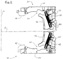
- FIG. 1 An improved two piece segmented mold is shown in section view in Fig. 1 in a closed position and in Fig. 2 in an open position.
- Fig. 1 and Fig. 2 show a right hand side of the mold, it being understood that, with respect to the subject matter of the invention, the left side is a mirror image.
- the section in Fig. 1 is taken through a guide arrangement, and Fig. 2 through a spring arrangement, which are further described below.
- a mold axial center line A and a parting line P are indicated in broken lines.
- the mold includes a top shell 20 and a bottom shell 40 that are relatively movable in a vertical direction (parallel to axis A) and separate at the parting line P for loading and unloading tires.
- the top shell 20 includes a top mold back 22 that forms a ring to support the other mold elements, a top side plate 24 that molds the side wall of the tire, and a plurality of tread mold segments 26 movably mounted to the top mold back 22.
- a bead ring 25 attached to the top side plate 24 molds the bead portion of the tire.
- the mold bottom shell 40 similarly includes a mold back 42, a bottom side plate 44, and a plurality of tread mold segments 46. Also shown is a bottom bead ring 45.
- top mold shell 20 and bottom mold shell 40 are axially spaced from the parting line P.
- the top tread mold segments 26 and bottom tread mold segments 46 are spaced from the respective top and bottom side plate 24, 44 both vertically (or axially) and radially outward.
- the tread mold segments 26, 46 are also mutually circumferentially spaced in the open position.
- the top mold back 22 and bottom mold back 42 are each formed with a frustoconical seat 28, 48 that diverges away from the respective mold side plate 24, 44, allowing the tread segments to move to the axially and radially spaced open position shown in Fig. 2.
- the segments 46 (it being understood that the top mold half segments 26 are similar) are guided for movement by a guide bar 50 fastened or formed on the back of the segment that engages a guide slot 52 formed in the mold back seat 28, 48.
- the guide bar 50 and guide slot 52 are T-shaped to constrain movement along the direction of the slot and prevent pivoting of the segment relative to the mold back.
- the segments 26, 46 are biased to assume a normally closed position, the position shown in Fig. 1. In the closed position, the segments 26, 46 abut the respective side plate 24, 44, and abut each adjacent segment. As seen in Fig. 2, in the open position, a gap 60 is formed between the segments 26, 46 and the respective side plate 24, 44. When an uncured tire is placed in an open mold, the tire can become pinched in the gap 60 when the mold is closed because uncured rubber is relatively soft and pliable. This results in flashing at the gap area, which is unsightly and undesirable.
- FIG. 3 is an enlarged section of Fig. 2 showing a biasing device in accordance with a preferred embodiment of the invention.
- a pair of extension springs 70 are mounted in cavities 72 in each segment 26, 46 and attached to the respective mold back 22, 42 to act in parallel with the frustoconical seat. As seen in Fig. 5, the springs 70 are mounted on either side of the guide bar 50.
- a removable head plate 74 retains the springs 70 and allows access for maintenance or replacement.
- the segments are biased to assume the open position. This is believed in the art to assist in releasing the tire tread from the mold segments.
- the present inventors have found that the opening action of the mold itself allows the molded tire to carry the segments until the radially outward movement of the segments along the respective seats releases them from the tire tread.
- FIG. 2 another feature of the mold of the invention is a vacuum system to evacuate air from the interior of the mold as it closes.
- a resilient skirt 80 is attached to the top mold back 22 and extends axially downward. The skirt 80 engages the bottom mold back 42 before the mold parts close, creating a seal around the partially open mold.
- a vacuum source (not shown) activates when the skirt engages the bottom mold back 42 to evacuate air from the interior of the mold, which helps ensure that air is not trapped between the uncured tire and the molding surfaces.
Landscapes
- Engineering & Computer Science (AREA)
- Mechanical Engineering (AREA)
- Moulds For Moulding Plastics Or The Like (AREA)
- Heating, Cooling, Or Curing Plastics Or The Like In General (AREA)
Abstract
Description
Claims (6)
- A two-piece segmented mold, comprising:a top half shell (20) having a top side part (24) and a top back part (22), the top back part having a frustoconical seat (28) extending axially inward and radially outward from the top side part (24);a plurality of tread mold segments (26) movably mounted to the seat to define a portion of a tread ring;biasing means to urge the tread mold segments to a closed position in mutual abutment and in abutment with the top side part (24);a bottom half shell (40) having a bottom side part (44) and a bottom back part (42), the bottom back part having a frustoconical seat (48) extending axially inward and radially outward from the bottom side part;a plurality of tread mold segments (46) movably mounted to the seat to define a portion of a tread ring; and,biasing means to urge the tread mold segments to a closed position in mutual abutment and in abutment with the bottom side part.
- The two-piece segmented mold as claimed in claim 1, wherein the biasing means comprises in each tread mold segment (26, 46) a pair of springs (70) connected between the tread mold segment and the respective mold back part (22, 42).
- The two-piece segmented mold as claimed in claim 1, further comprising a plurality of T-shaped guide bars (50), one guide bar mounted to each of the plurality of tread mold segments and wherein the seats (28, 48) of the top back part and bottom back part have a plurality of T-shaped slots (52), each guide bar being inserted for sliding in a slot.
- The two-piece segmented mold as claimed in claim 1, wherein the biasing means in the bottom half shell is gravity acting on the tread mold segment.
- The two-piece segmented mold as claimed in claim 4, wherein the biasing means in the top half shell (20) includes a plurality of springs (70), a pair of springs acting on each tread mold segment (26).
- The two-piece segmented mold as claimed in claim 1, further comprising a skirt (80) mounted to the top half shell (20) and depending axially downward therefrom for engaging the bottom half shell (40) to form an air seal about a mold interior, and a vacuum source for evacuating air from the mold interior.
Applications Claiming Priority (2)
| Application Number | Priority Date | Filing Date | Title |
|---|---|---|---|
| US663290 | 2000-09-15 | ||
| US09/663,290 US6318985B1 (en) | 2000-09-15 | 2000-09-15 | Two-piece segmented mold |
Publications (2)
| Publication Number | Publication Date |
|---|---|
| EP1188532A2 true EP1188532A2 (en) | 2002-03-20 |
| EP1188532A3 EP1188532A3 (en) | 2003-07-16 |
Family
ID=24661199
Family Applications (1)
| Application Number | Title | Priority Date | Filing Date |
|---|---|---|---|
| EP01121547A Withdrawn EP1188532A3 (en) | 2000-09-15 | 2001-09-10 | Two-piece segmented mold for tires |
Country Status (6)
| Country | Link |
|---|---|
| US (1) | US6318985B1 (en) |
| EP (1) | EP1188532A3 (en) |
| CN (1) | CN1176795C (en) |
| CA (1) | CA2356467A1 (en) |
| MX (1) | MXPA01009273A (en) |
| PL (1) | PL349683A1 (en) |
Families Citing this family (20)
| Publication number | Priority date | Publication date | Assignee | Title |
|---|---|---|---|---|
| JP4236413B2 (en) * | 2002-02-15 | 2009-03-11 | 株式会社ブリヂストン | Tire vulcanizer |
| JP4414339B2 (en) * | 2002-11-04 | 2010-02-10 | ソシエテ ドゥ テクノロジー ミシュラン | Tire mold and method for manufacturing tire mold |
| US20060125147A1 (en) * | 2004-12-03 | 2006-06-15 | Bachochin Todd A | Segmented tire mold for off-road-vehicle tires |
| JP4702130B2 (en) * | 2006-03-22 | 2011-06-15 | 横浜ゴム株式会社 | Two-part mold for tire molding |
| JP4930063B2 (en) * | 2007-01-11 | 2012-05-09 | 横浜ゴム株式会社 | Two-part mold for tire molding |
| JP4345898B2 (en) * | 2008-02-25 | 2009-10-14 | 横浜ゴム株式会社 | Pneumatic tire vulcanizing apparatus and method |
| BRPI0822855A2 (en) * | 2008-06-27 | 2015-06-30 | Michelin Rech Tech | Tire Curing Mold |
| EP2296860B1 (en) * | 2008-06-30 | 2015-01-28 | MICHELIN Recherche et Technique S.A. | Tire mold with positive mold opening system |
| US7963756B2 (en) * | 2009-11-18 | 2011-06-21 | The Goodyear Tire & Rubber Company | Segmented tire mold |
| US20130099419A1 (en) * | 2011-10-25 | 2013-04-25 | Neal G. Sehm | Convertible two piece sideplate |
| US8535031B2 (en) * | 2012-02-14 | 2013-09-17 | Bridgestone Americas Tire Operations, Llc | Pneumatic tire mold adapter |
| FR2998828B1 (en) * | 2012-12-04 | 2015-05-15 | Michelin & Cie | VULCANIZATION MOLD FOR TIRES |
| US9604423B2 (en) | 2013-06-28 | 2017-03-28 | Compagnie Generale Des Etablissements Michelin | Tire mold with improved durability |
| US10766215B2 (en) * | 2016-01-21 | 2020-09-08 | Bridgestone Americas Tire Operations, Llc | Adjustable tire mold |
| FR3051387A1 (en) * | 2016-05-17 | 2017-11-24 | Michelin & Cie | DEVICE FOR VULCANIZING TIRES |
| FR3064520A1 (en) | 2017-03-29 | 2018-10-05 | Compagnie Generale Des Etablissements Michelin | PNEUMATIC COOKING MOLD WITH HALF SECTIONS |
| US10870248B2 (en) * | 2018-03-23 | 2020-12-22 | Bridgestone Americas Tire Operations, Llc | Non-symmetrical tread ring parting line mold |
| JP7234752B2 (en) * | 2019-04-03 | 2023-03-08 | 住友ゴム工業株式会社 | Tire vulcanizing device and tire vulcanizing method |
| CN113306182B (en) * | 2021-07-13 | 2022-12-27 | 山东豪迈机械科技股份有限公司 | Tire segmented mold |
| CN113246516B (en) * | 2021-07-14 | 2021-10-08 | 山东豪迈机械科技股份有限公司 | Tire two-half movable mold with synchronous structure |
Family Cites Families (10)
| Publication number | Priority date | Publication date | Assignee | Title |
|---|---|---|---|---|
| DE1160606B (en) * | 1960-08-20 | 1964-01-02 | Continental Gummi Werke Ag | Vulcanizing mold for pneumatic vehicle tires |
| US3778203A (en) * | 1972-04-11 | 1973-12-11 | K Macmillan | Matrix assembly with segmented matrices |
| DE2502185C3 (en) * | 1975-01-21 | 1982-02-04 | Continental Gummi-Werke Ag, 3000 Hannover | Vulcanizing mold for pneumatic vehicle tires |
| US4025250A (en) * | 1975-11-25 | 1977-05-24 | Macmillan Mold Co., Inc. | Segmented matrix with guide means and retaining pins |
| US4573894A (en) * | 1984-11-23 | 1986-03-04 | The B. F. Goodrich Company | Apparatus for ventless tire molding |
| KR940004796B1 (en) * | 1989-02-15 | 1994-06-01 | 스미또모 고무 고오교오 가부시끼가이샤 | Mold for molding vulcanizatian |
| US5405568A (en) * | 1992-10-26 | 1995-04-11 | The Goodyear Tire & Rubber Company | Two-piece segmented tire mold and method of molding |
| FR2712229A1 (en) * | 1993-11-12 | 1995-05-19 | Sedepro | Tire mold, and tire molding method. |
| US5676980A (en) * | 1995-09-29 | 1997-10-14 | Continental General Tire, Inc. | Center split segmented mold for curing pneumatic tires |
| FR2759626A1 (en) * | 1997-02-19 | 1998-08-21 | Sedepro | TIRE MOLD |
-
2000
- 2000-09-15 US US09/663,290 patent/US6318985B1/en not_active Expired - Lifetime
-
2001
- 2001-09-05 CA CA002356467A patent/CA2356467A1/en not_active Abandoned
- 2001-09-10 EP EP01121547A patent/EP1188532A3/en not_active Withdrawn
- 2001-09-12 CN CNB011314990A patent/CN1176795C/en not_active Expired - Fee Related
- 2001-09-13 MX MXPA01009273A patent/MXPA01009273A/en unknown
- 2001-09-14 PL PL01349683A patent/PL349683A1/en not_active Application Discontinuation
Also Published As
| Publication number | Publication date |
|---|---|
| JP2002137228A (en) | 2002-05-14 |
| JP3608161B2 (en) | 2005-01-05 |
| CN1344609A (en) | 2002-04-17 |
| CN1176795C (en) | 2004-11-24 |
| EP1188532A3 (en) | 2003-07-16 |
| CA2356467A1 (en) | 2002-03-15 |
| MXPA01009273A (en) | 2003-08-20 |
| US6318985B1 (en) | 2001-11-20 |
| PL349683A1 (en) | 2002-03-25 |
Similar Documents
| Publication | Publication Date | Title |
|---|---|---|
| US6318985B1 (en) | Two-piece segmented mold | |
| US8657599B2 (en) | Device for demoulding negatives in plastic injection | |
| CN101797778B (en) | Vulcanizing mold of tire | |
| JP3874507B2 (en) | Tire vulcanizer | |
| CN102470619A (en) | Sector mold with radial recoil | |
| CA1106561A (en) | Tire curing press | |
| CN108463322B (en) | Tire blank curing machine including connecting tie rods | |
| JP7064423B2 (en) | Tire vulcanizer | |
| JP4603709B2 (en) | Tire vulcanization mold and tire manufacturing method | |
| CN116118241B (en) | Tire molds for ventless tire molding | |
| JP3853211B2 (en) | Tire vulcanizing method and apparatus | |
| JP5268631B2 (en) | Mold for vulcanizing unvulcanized tire blanks | |
| CN116118240B (en) | Tire forming process | |
| EP4427903B1 (en) | Tire molding mold and tire manufacturing method | |
| CN114364523B (en) | Mould for tyre shaping | |
| WO2000021727A1 (en) | Method and apparatus for molding a tire | |
| CN117480041A (en) | Mold for forming tires and tire production method | |
| CN117529396B (en) | Mold for forming tire and tire production method | |
| JP3608161B6 (en) | Two-piece split mold | |
| SU1362638A1 (en) | Sector injection mould for vulcanizing the casings of pneumatic tyres | |
| US12290999B2 (en) | Molding method for tire production | |
| JP2025158806A (en) | Tire mold | |
| JP4909057B2 (en) | Tire mold | |
| CN117940276A (en) | Lining element for a tire mold | |
| JP2008207414A (en) | Tire vulcanizing method and tire vulcanizing mold |
Legal Events
| Date | Code | Title | Description |
|---|---|---|---|
| PUAI | Public reference made under article 153(3) epc to a published international application that has entered the european phase |
Free format text: ORIGINAL CODE: 0009012 |
|
| AK | Designated contracting states |
Kind code of ref document: A2 Designated state(s): AT BE CH CY DE DK ES FI FR GB GR IE IT LI LU MC NL PT SE TR |
|
| AX | Request for extension of the european patent |
Free format text: AL;LT;LV;MK;RO;SI |
|
| PUAL | Search report despatched |
Free format text: ORIGINAL CODE: 0009013 |
|
| AK | Designated contracting states |
Designated state(s): AT BE CH CY DE DK ES FI FR GB GR IE IT LI LU MC NL PT SE TR |
|
| AX | Request for extension of the european patent |
Extension state: AL LT LV MK RO SI |
|
| STAA | Information on the status of an ep patent application or granted ep patent |
Free format text: STATUS: THE APPLICATION HAS BEEN WITHDRAWN |
|
| 18W | Application withdrawn |
Effective date: 20040116 |