EP1187762B1 - Laminar flow control system and suction panel for use therewith - Google Patents
Laminar flow control system and suction panel for use therewith Download PDFInfo
- Publication number
- EP1187762B1 EP1187762B1 EP00937071A EP00937071A EP1187762B1 EP 1187762 B1 EP1187762 B1 EP 1187762B1 EP 00937071 A EP00937071 A EP 00937071A EP 00937071 A EP00937071 A EP 00937071A EP 1187762 B1 EP1187762 B1 EP 1187762B1
- Authority
- EP
- European Patent Office
- Prior art keywords
- micro
- suction panel
- micro channel
- skin
- suction
- Prior art date
- Legal status (The legal status is an assumption and is not a legal conclusion. Google has not performed a legal analysis and makes no representation as to the accuracy of the status listed.)
- Expired - Lifetime
Links
- 238000004519 manufacturing process Methods 0.000 claims description 5
- OKTJSMMVPCPJKN-UHFFFAOYSA-N Carbon Chemical compound [C] OKTJSMMVPCPJKN-UHFFFAOYSA-N 0.000 claims description 4
- 229910052799 carbon Inorganic materials 0.000 claims description 4
- 239000002131 composite material Substances 0.000 claims description 4
- 239000000835 fiber Substances 0.000 claims description 4
- 239000000463 material Substances 0.000 claims description 3
- 229910052751 metal Inorganic materials 0.000 claims description 2
- 239000002184 metal Substances 0.000 claims description 2
- 238000004891 communication Methods 0.000 abstract description 3
- 238000010348 incorporation Methods 0.000 abstract 1
- 238000000034 method Methods 0.000 description 4
- RTAQQCXQSZGOHL-UHFFFAOYSA-N Titanium Chemical compound [Ti] RTAQQCXQSZGOHL-UHFFFAOYSA-N 0.000 description 3
- 238000005553 drilling Methods 0.000 description 3
- 239000010936 titanium Substances 0.000 description 3
- 229910052719 titanium Inorganic materials 0.000 description 3
- 238000010276 construction Methods 0.000 description 2
- 238000004026 adhesive bonding Methods 0.000 description 1
- 238000005459 micromachining Methods 0.000 description 1
- 238000012986 modification Methods 0.000 description 1
- 230000004048 modification Effects 0.000 description 1
- 239000007787 solid Substances 0.000 description 1
- 230000007704 transition Effects 0.000 description 1
Images

Classifications
-
- F—MECHANICAL ENGINEERING; LIGHTING; HEATING; WEAPONS; BLASTING
- F15—FLUID-PRESSURE ACTUATORS; HYDRAULICS OR PNEUMATICS IN GENERAL
- F15D—FLUID DYNAMICS, i.e. METHODS OR MEANS FOR INFLUENCING THE FLOW OF GASES OR LIQUIDS
- F15D1/00—Influencing flow of fluids
- F15D1/10—Influencing flow of fluids around bodies of solid material
- F15D1/12—Influencing flow of fluids around bodies of solid material by influencing the boundary layer
-
- B—PERFORMING OPERATIONS; TRANSPORTING
- B64—AIRCRAFT; AVIATION; COSMONAUTICS
- B64C—AEROPLANES; HELICOPTERS
- B64C1/00—Fuselages; Constructional features common to fuselages, wings, stabilising surfaces or the like
- B64C1/06—Frames; Stringers; Longerons ; Fuselage sections
- B64C1/12—Construction or attachment of skin panels
-
- B—PERFORMING OPERATIONS; TRANSPORTING
- B64—AIRCRAFT; AVIATION; COSMONAUTICS
- B64C—AEROPLANES; HELICOPTERS
- B64C21/00—Influencing air flow over aircraft surfaces by affecting boundary layer flow
- B64C21/02—Influencing air flow over aircraft surfaces by affecting boundary layer flow by use of slot, ducts, porous areas or the like
- B64C21/06—Influencing air flow over aircraft surfaces by affecting boundary layer flow by use of slot, ducts, porous areas or the like for sucking
-
- B—PERFORMING OPERATIONS; TRANSPORTING
- B64—AIRCRAFT; AVIATION; COSMONAUTICS
- B64C—AEROPLANES; HELICOPTERS
- B64C3/00—Wings
- B64C3/26—Construction, shape, or attachment of separate skins, e.g. panels
-
- B—PERFORMING OPERATIONS; TRANSPORTING
- B64—AIRCRAFT; AVIATION; COSMONAUTICS
- B64C—AEROPLANES; HELICOPTERS
- B64C2230/00—Boundary layer controls
- B64C2230/04—Boundary layer controls by actively generating fluid flow
-
- B—PERFORMING OPERATIONS; TRANSPORTING
- B64—AIRCRAFT; AVIATION; COSMONAUTICS
- B64C—AEROPLANES; HELICOPTERS
- B64C2230/00—Boundary layer controls
- B64C2230/22—Boundary layer controls by using a surface having multiple apertures of relatively small openings other than slots
-
- Y—GENERAL TAGGING OF NEW TECHNOLOGICAL DEVELOPMENTS; GENERAL TAGGING OF CROSS-SECTIONAL TECHNOLOGIES SPANNING OVER SEVERAL SECTIONS OF THE IPC; TECHNICAL SUBJECTS COVERED BY FORMER USPC CROSS-REFERENCE ART COLLECTIONS [XRACs] AND DIGESTS
- Y02—TECHNOLOGIES OR APPLICATIONS FOR MITIGATION OR ADAPTATION AGAINST CLIMATE CHANGE
- Y02T—CLIMATE CHANGE MITIGATION TECHNOLOGIES RELATED TO TRANSPORTATION
- Y02T50/00—Aeronautics or air transport
- Y02T50/10—Drag reduction
Definitions
- the present invention relates to a laminar flow control system (LFC) and to a suction panel for use therewith, although such a suction panel could have other uses.
- LFC laminar flow control system
- LFC laminar flow control system
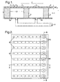
- LFC systems which comprise a panel 1, in the form of a perforated skin 2, typically made of titanium and mounted on large scale plenum chambers 3a, 3b etc. This is illustrated in Figure 1.
- the air flow is on the top surface of the system above the panel 1 as indicated by the arrow Z in Figure 1.
- suction is applied through the perforated skin 2 through a series of large scale plenum chambers 3a, 3b... as illustrated.
- the plenum chambers 3a, 3b... are connected together by pipework and suction is applied as indicated by arrow Y in Figure 1.
- the pressures could be P 1 >P 2 >P 3 ....>P x (or reverse). It is necessary to make sure that no flow occurs through holes 4 in the skin 2 and in the plenum chambers 3a, 3b... to cause this pressure gradient to equalise (a condition known as outflow). To avoid this the pressure drop ⁇ P p across the perforated skin 2 needs to be greater than P x -P 1 .
- ⁇ P p is limited by the maximum pitch and the size of the holes 4 that can be drilled. The pitch is limited by the requirement to have effectively uniform suction and the hole size is limited by the drilling process. In addition, there is a requirement that the suction velocity in a particular hole 4 does not exceed a critical value that would disturb the flow.
- the pressure of the plenum chambers reduces the overall stiffness of the suction panel. This leads to the need for a thicker, heavier weight strain to improve the stiffness but at the expense of undesirably increasing the weight of the panel.
- a suction control panel comprising a structure has an outer surface formed by a sheet bearing a large number of very small holes that communicate with a plurality of slits and channels that are in turn connected via manifolds to a pump.
- the slits and channels are paired to form a common micro channel that connects a number of the holes provided in the sheet.
- Each micro channel is symmetrical about its midpoint, in both longitudinal and transverse directions, such that the cross-sectional area of the micro channel is the same at the same distance from the midpoint including at the ends.
- a suction panel for use in a laminar flow control system, including a perforated skin that is supported on a base member and micro channels formed either in the mounted side of the skin or in the base member, the base member having formed therein a plenum chamber with each micro channel communicating with the plenum chamber, characterised in that the cross-sectional area of a micro channel increases from one end of the micro channel to the other end of the micro channel.
- the width of a micro channel may increase from one end of the micro channel to the other end of the micro channel.
- the width of a micro channel may taper uniformly from one end of the micro channel to the other end of the micro channel or, alternatively, may taper stepwise from one end of the micro channel to the other end of the micro channel.
- the micro channels extends substantially in parallel and the plenum chamber extends substantially perpendicularly to the micro channels.
- the perforated skin may be mounted on a base member having a first base layer and a second base layer, the micro channels being formed in the second base layer and at least one plenum chamber being formed in the first base layer, with the micro channels being such that a controlled pressure gradient can be established therealong to ensure no outflow therefrom via the skin perforations.
- the perforated skin is bonded to the base member.
- the support, first base layer or second base layer may comprise one or more layers of carbon fibre composite (CFC).
- CFC carbon fibre composite
- the perforated skin is a metal.
- perforated skin is made of a pliable material which enables it to be stretched over a surface on which it is mounted.
- a laminar flow control system which comprises a suction panel as specified in the immediately preceding paragraphs and means for applying suction to the plenum chamber in order to maintain boundary layer suction to a free surface of the perforated skin.
- a method of manufacturing a suction panel as specified in the immediately preceding paragraphs including the step of employing a laser beam to form the micro-channels and the perforations in the skin.
- an aircraft flying surface incorporating a suction panel as specified in the immediately preceding paragraphs or a laminar flow control system as specified in two paragraphs above.
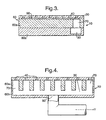
- a suction panel 10 for an LFC system is shown in Figures 2 to 6.
- the suction panel 10 comprises a perforated skin 20 having holes 40, which skin is supported on a base member 60 which comprises a first layer 60a and a second base layer 60b each of a carbon fibre composite (CFC).
- CFC carbon fibre composite
- the first or upper CFC base layer 60a supports the skin 20, as indicated in Figure 4, and has formed in it suction holes 70, the second or bottom CFC base layer 60b supporting the upper CFC base layer 60a and having formed therein a plenum chamber 30 to which suction Y can be applied via a main suction hole 80.
- the CFC base layers 60a and 60b are glued to one another and the perforated skin 20 is also glued to the upper CFC base layer 60a.
- the perforated skin 20 will be made of titanium and will be drilled with micro holes of about 50 microns diameter on a 10:1 pitch diameter ratio. For clarity, there are only eight rows of nine holes but in an actual system the number of holes may be much higher.
- Each of the micro holes 40 in a row communicates with the same micro channel 90, as shown in Figure 3, each micro channel communicating at one end with a suction hole 70 which is formed in the first or upper CFC base layer 60a.
- Each micro channel 90 has constant cross-sectional area and so this suction panel 10 is outside the scope of the present invention.
- each micro channel 90 is preferably in the range of one to four times the diameter of the holes 40.
- the pressure gradient requirements for flow within the micro channels 90 would be obtained by the width of the micro channels, together with their depth.
- a relatively large hole 70 is drilled through the upper CFC base layer 60a to allow suction to be applied to the micro channels.
- the plenum chamber 30 in the lower CFC base layer 60b is in communication with each of the suction holes 70.
- the pressure drop across the perforated skin 20 ⁇ P p needs to be greater than P 1 -P x .
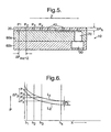
- Figure 6 illustrates the idealised pressure profile and in this case the pressure profile is the same as on the top surface of the perforated skin 20 but reduced by the pressure drop induced by the flow through the individual hole ⁇ P h .
- ⁇ P h can be much smaller than ⁇ P p as it is summed with ⁇ P mc[x ⁇ (x+1)] and P x - P x+1 will be much smaller than P 1 - P x .
- the micro holes can be larger and, more importantly, the perforated skin can be much thinner. This is especially the case when it is realised the skin is everywhere supported between the rows of holes. This means that a much lighter, thinner skin and hence a lighter suction panel would be possible.
- Figures 7 and 8 are plan and sectional views respectively of an individual micro channel 90 according to a first embodiment of the present invention taken on line C-C of Figure 7.
- the pressure loss in the micro channel 90 will, to a first order, be directly proportional to the cross-sectional area of the channel which in turn depends on the dimensions W and d as shown in Figure 8.
- the dimension W may be varied to give the varying pressure loss and required pressure gradient but this could also be achieved by varying d or indeed by varying both W and d.
- the micro channels 90 are aligned with the micro channel suction holes 70 and the plenum chamber 30 at the low pressure end of the pressure gradient. Therefore, if the pressure gradient is reversed compared to those described, then the channels would extend to the right of the plenum chamber. At the point where the pressure gradient changes sign, the micro channels could then extend both left and right from the plenum chamber.
- Figure 9 is a similar view to Figure 7 but shows a variation in the plan shape of the micro channel 90 in accordance with a second embodiment of the present invention.
- Figure 10 is also a view similar to Figure 7 but showing an arrangement in which there is more than one (in this case four) row of holes 40 in each micro channel 90, in this example there being two suction holes 80 in each micro channel 90. With this arrangement there would be an enlarged bonding area between each of the two micro channels illustrated, these micro channels being enlarged in the non-flow direction.
- the cross-sectional area of each micro channel 90 is uniform, and so the suction panel 10 of Figure 10 is outside the scope of the present invention.
- One advantage of the present invention is that any variations in the drilling of the micro holes 40 can be easily compensated for. This contrasts with the prior art method of manufacturing an LFC system where the plenum chambers are designed and then a performance specification is determined for the pressure loss characteristics of the perforated skin 2.
- the drilling and forming process for the panel is not sufficiently well controlled or well-known to allow very precise control of the pressure loss characteristics.
- those characteristics vary across the panel and there is currently no way of compensating for this.
- the perforated panel can be manufactured and the pressure loss characteristics then measured.
- the micro channels in the upper CFC base member 60a can then be tailored to the pressure loss characteristics of the perforated skin 20.
Landscapes
- Engineering & Computer Science (AREA)
- Mechanical Engineering (AREA)
- Aviation & Aerospace Engineering (AREA)
- Chemical & Material Sciences (AREA)
- General Engineering & Computer Science (AREA)
- Fluid Mechanics (AREA)
- Physics & Mathematics (AREA)
- Combustion & Propulsion (AREA)
- Manipulator (AREA)
- Structures Of Non-Positive Displacement Pumps (AREA)
- Laminated Bodies (AREA)
- Physical Or Chemical Processes And Apparatus (AREA)
- Sheets, Magazines, And Separation Thereof (AREA)
- Load-Engaging Elements For Cranes (AREA)
- Delivering By Means Of Belts And Rollers (AREA)
Abstract
Description
- The present invention relates to a laminar flow control system (LFC) and to a suction panel for use therewith, although such a suction panel could have other uses.
- The specific application of the present invention is in a laminar flow control system (LFC) which could be incorporated into an aircraft wing or other aerodynamic surface where it is desired to control the flow of air over the surface.
- There are known LFC systems which comprise a
panel 1, in the form of aperforated skin 2, typically made of titanium and mounted on largescale plenum chambers panel 1 as indicated by the arrow Z in Figure 1. To maintain boundary layer control, suction is applied through theperforated skin 2 through a series of largescale plenum chambers plenum chambers skin 2 and in theplenum chambers perforated skin 2 needs to be greater than Px-P1. ΔPp is limited by the maximum pitch and the size of the holes 4 that can be drilled. The pitch is limited by the requirement to have effectively uniform suction and the hole size is limited by the drilling process. In addition, there is a requirement that the suction velocity in a particular hole 4 does not exceed a critical value that would disturb the flow. - These operational and mechanical integrity restrictions mean that there is a maximum size for the dimension D of each
plenum chamber plenum chambers - For example the pressure of the plenum chambers reduces the overall stiffness of the suction panel. This leads to the need for a thicker, heavier weight strain to improve the stiffness but at the expense of undesirably increasing the weight of the panel.
- In areas where a
wall 5 of theplenum chamber perforated skin 2 there is no suction. These areas are relatively large in order to provide the necessary mechanical integrity to the structure. This will destabilise the flow and in the worst case could cause a transition to turbulent flow. The problem would get worse with larger plenum chambers as bigger skin support landings would be required. Therefore a significant fraction of the surface contains regions with no suction. In the panel shown in Figure 1 theperforated skin 2 is typically 1-2 mm thick and the overall depth or thickness of the panel as a whole, i.e. dimension E, is 2-3 cms. Overlap of the holes 4 bywall 5, typically of the order of 3 to 5mm, causes loss of suction. D is typically 3 to 5cms. - A similar arrangement to that shown in Figure 1 is described in EP-A1-0,536,874, where a suction control panel comprising a structure has an outer surface formed by a sheet bearing a large number of very small holes that communicate with a plurality of slits and channels that are in turn connected via manifolds to a pump. The slits and channels are paired to form a common micro channel that connects a number of the holes provided in the sheet. Each micro channel is symmetrical about its midpoint, in both longitudinal and transverse directions, such that the cross-sectional area of the micro channel is the same at the same distance from the midpoint including at the ends.
- According to one aspect of the present invention there is provided a suction panel for use in a laminar flow control system, including a perforated skin that is supported on a base member and micro channels formed either in the mounted side of the skin or in the base member, the base member having formed therein a plenum chamber with each micro channel communicating with the plenum chamber, characterised in that the cross-sectional area of a micro channel increases from one end of the micro channel to the other end of the micro channel.
- Optionally, the width of a micro channel may increase from one end of the micro channel to the other end of the micro channel. Conveniently, the width of a micro channel may taper uniformly from one end of the micro channel to the other end of the micro channel or, alternatively, may taper stepwise from one end of the micro channel to the other end of the micro channel.
- Preferably, the micro channels extends substantially in parallel and the plenum chamber extends substantially perpendicularly to the micro channels.
- Optionally, the perforated skin may be mounted on a base member having a first base layer and a second base layer, the micro channels being formed in the second base layer and at least one plenum chamber being formed in the first base layer, with the micro channels being such that a controlled pressure gradient can be established therealong to ensure no outflow therefrom via the skin perforations.
- Preferably, the perforated skin is bonded to the base member.
- Optionally, the support, first base layer or second base layer may comprise one or more layers of carbon fibre composite (CFC).
- Preferably, the perforated skin is a metal. Alternatively, perforated skin is made of a pliable material which enables it to be stretched over a surface on which it is mounted.
- According to another aspect of the present invention, there is provided a laminar flow control system which comprises a suction panel as specified in the immediately preceding paragraphs and means for applying suction to the plenum chamber in order to maintain boundary layer suction to a free surface of the perforated skin.
- According to a further aspect of the present invention, there is provided a method of manufacturing a suction panel as specified in the immediately preceding paragraphs including the step of employing a laser beam to form the micro-channels and the perforations in the skin.
- According to yet another aspect of the present invention there is provided, an aircraft flying surface incorporating a suction panel as specified in the immediately preceding paragraphs or a laminar flow control system as specified in two paragraphs above.
- How the invention may be carried out will now be described by way of example only and with reference to the accompanying drawings in which:
- Figure 1 is a sectional view of a known laminar flow control system;
- Figure 2 is a plan view of a suction panel for use in a laminar flow control system;
- Figure 3 is a section taken on the line A-A of Figure 2;
- Figure 4 is a section taken on the line B-B of Figure 2;
- Figure 5 is a section substantially the same as Figure 3 but illustrates pressures at individual apertures in the perforated skin;
- Figure 6 is a graph illustrating the pressure characteristics of the construction shown in Figure 5;
- Figure 7 is a plan view of a stepped-tapered micro-channel according to a first embodiment of the present invention;
- Figure 8 is a section taken on the line C-C of Figure 7;
- Figure 9 is a plan view similar to Figure 7 but showing a continuously tapered micro-channel according to a second embodiment of the present invention; and
- Figure 10 is a plan view of a further micro-channel configuration in which each micro-channel contains more than one row of micro apertures.
-
- A known prior art arrangement is illustrated in Figure 1 and has already been described.
- As background to the present invention, a
suction panel 10 for an LFC system is shown in Figures 2 to 6. Thesuction panel 10 comprises aperforated skin 20 havingholes 40, which skin is supported on abase member 60 which comprises afirst layer 60a and asecond base layer 60b each of a carbon fibre composite (CFC). - The first or upper
CFC base layer 60a supports theskin 20, as indicated in Figure 4, and has formed in itsuction holes 70, the second or bottomCFC base layer 60b supporting the upperCFC base layer 60a and having formed therein aplenum chamber 30 to which suction Y can be applied via amain suction hole 80. - The
CFC base layers perforated skin 20 is also glued to the upperCFC base layer 60a. - Typically, the
perforated skin 20 will be made of titanium and will be drilled with micro holes of about 50 microns diameter on a 10:1 pitch diameter ratio. For clarity, there are only eight rows of nine holes but in an actual system the number of holes may be much higher. Each of themicro holes 40 in a row communicates with the samemicro channel 90, as shown in Figure 3, each micro channel communicating at one end with asuction hole 70 which is formed in the first or upperCFC base layer 60a. Eachmicro channel 90 has constant cross-sectional area and so thissuction panel 10 is outside the scope of the present invention. - The width of each
micro channel 90 is preferably in the range of one to four times the diameter of theholes 40. - The pressure gradient requirements for flow within the
micro channels 90 would be obtained by the width of the micro channels, together with their depth. - At the end of the micro channels 90 a relatively
large hole 70 is drilled through the upperCFC base layer 60a to allow suction to be applied to the micro channels. Theplenum chamber 30 in the lowerCFC base layer 60b is in communication with each of the suction holes 70. - It was mentioned earlier that the base layers 60a and 60b are glued together and that the
aperture skin 20 is glued to theupper base layer 60a. - In order to locate such glueing secondary micro channels could be micro-machined between the suction
micro channels 90 but these secondary micro channels are not illustrated in the drawings. - As indicated earlier, the detailed design of the
micro channels 90 is determined by the pressure gradient requirements of the particular application. In order to illustrate this, reference is made to Figures 5 and 6, Figure 5 being similar to Figure 3 in terms of the structure and Figure 6 being a graph plotting pressure P against position X for the top surface of theperforated skin 20, with the line L1 showing the pressure profile on the outer surface of the skin, and line L2 showing the idealised pressure profile in the machinedmicrochannel 90. - In general there will be some pressure gradient in the direction of the flow Z and, in this case, the pressure will be higher on the left-hand side from the right-hand side but the reverse could apply. In this example P1>P2>P3....>Px.
- If a simple large
scale plenum chamber 3 is used, then the pressure drop across theperforated skin 20 ΔPp needs to be greater than P1-Px. Clearly, the larger the number ofholes 70 contained in the plenum chamber, the larger ΔPp. - Figure 6 illustrates the idealised pressure profile and in this case the pressure profile is the same as on the top surface of the
perforated skin 20 but reduced by the pressure drop induced by the flow through the individual hole ΔPh. - This arrangement would always guarantee no outflow because the pressure at all the holes is less in the micro channel than that on the surface of the
perforated skin 20. The pressure curve could, in fact, be lower than that shown in Figure 6 in order to guarantee that this is the position but there is a limit to how far such a lowering could take place. This limit is that ΔPh is not so large that the flow velocity through an individual hole exceeds the critical suction velocity as described previously. - The worst case in the other direction is to assume that the micro channel looks like a large plenum chamber with no pressure gradient. In that case ΔPh would need to be equal to P1-Px as before.
- The requirement for no outflow at any hole is that the sum of the pressure loss through the hole and the pressure due to flow in the micro channel must be greater than the difference in pressure of the surface for the two holes. This can be expressed as:
- To understand how a pressure profile as shown in Figure 6 may be realised in practice according to the present invention, reference is now made to Figures 7 and 8.
- Figures 7 and 8 are plan and sectional views respectively of an individual
micro channel 90 according to a first embodiment of the present invention taken on line C-C of Figure 7. - The pressure loss in the
micro channel 90 will, to a first order, be directly proportional to the cross-sectional area of the channel which in turn depends on the dimensions W and d as shown in Figure 8. The dimension W may be varied to give the varying pressure loss and required pressure gradient but this could also be achieved by varying d or indeed by varying both W and d. - The
micro channels 90 are aligned with the micro channel suction holes 70 and theplenum chamber 30 at the low pressure end of the pressure gradient. Therefore, if the pressure gradient is reversed compared to those described, then the channels would extend to the right of the plenum chamber. At the point where the pressure gradient changes sign, the micro channels could then extend both left and right from the plenum chamber. - Figure 9 is a similar view to Figure 7 but shows a variation in the plan shape of the
micro channel 90 in accordance with a second embodiment of the present invention. - Figure 10 is also a view similar to Figure 7 but showing an arrangement in which there is more than one (in this case four) row of
holes 40 in eachmicro channel 90, in this example there being twosuction holes 80 in eachmicro channel 90. With this arrangement there would be an enlarged bonding area between each of the two micro channels illustrated, these micro channels being enlarged in the non-flow direction. The cross-sectional area of eachmicro channel 90 is uniform, and so thesuction panel 10 of Figure 10 is outside the scope of the present invention. - A number of variations could be made to the specific embodiments previously described with reference to the accompanying drawings, these modifications including the following:
- a) materials other than titanium and carbon fibre composite could be used to manufacture the suction panel;
- b) techniques other than micro-machining could be employed for the forming of the micro channels;
- c) the
skin 20 could be stretched over the surface of theCFC base member 60; - d) the suction panel could be configured to have a single or multiple curvature;
- e) the
lower base member 60b could have a non-solid construction employing integral stiffness, thereby making it lighter, - f) the plenum chambers could be added separately;
- g) the
micro channels 90 could in fact be machined on the underside of theperforated skin 20, thus allowing easier fabrication; - h) the micro channels could be formed on the underside of the
skin 20 by means of a laser beam which could also be used to form the holes through theskin 20, this being achieved by the laser beam being held stationary for a short period at the position of the desired holes and then scanned between adjacent hole position to form the micro channel, thus ensuring alignment of the micro channel with the rows of holes. -
- One advantage of the present invention is that any variations in the drilling of the
micro holes 40 can be easily compensated for. This contrasts with the prior art method of manufacturing an LFC system where the plenum chambers are designed and then a performance specification is determined for the pressure loss characteristics of theperforated skin 2. - However, with this prior art method the drilling and forming process for the panel is not sufficiently well controlled or well-known to allow very precise control of the pressure loss characteristics. In addition, those characteristics vary across the panel and there is currently no way of compensating for this. With the present invention, the perforated panel can be manufactured and the pressure loss characteristics then measured. The micro channels in the upper
CFC base member 60a can then be tailored to the pressure loss characteristics of theperforated skin 20.
Claims (14)
- A suction panel (10) for use in a laminar flow control system, including a perforated skin (20) that is supported on a base member (60) and micro channels (90) formed either in the mounted side of the skin or in the base member, the base member having formed therein a plenum chamber (30) with each micro channel communicating with the plenum chamber, characterised in that the cross-sectional area of a micro channel increases from one end of the micro channel to the other end of the micro channel.
- A suction panel as daimed in Claim 1 in which the width of a micro channel increases from one end of the micro channel to the other end of the micro channel.
- A suction panel as claimed in Claim 2 in which the width of a micro channel tapers uniformly from one end of the micro channel to the other end of the micro channel.
- A suction panel as claimed in Claim 2 in which the width of a micro channel tapers stepwise from one end of the micro channel to the other end of the micro channel.
- A suction panel as claimed in any previous claim in which the micro channels extend substantially in parallel and the plenum chamber extends substantially perpendicularly to the micro channels.
- A suction panel as daimed in any previous claim in which the perforated skin is mounted on a base member having a first base layer (60b) and a second base layer (60a), the micro channels being formed in the second base layer and at least one plenum chamber being formed in the first base layer, with the micro channels being such that a controlled pressure gradient can be established therealong to ensure no outflow therefrom via the skin perforations (40).
- A suction panel as claimed in any previous claim in which the perforated skin is bonded to the base member.
- A suction panel as claimed in any previous claim in which the support, first base layer or second base layer comprises one or more layers of carbon fibre composite (CFC).
- A suction panel as claimed in any previous claim in which the perforated skin is a metal.
- A suction panel as claimed in any one of Claims 1 to 8 in which the perforated skin is made of a pliable material which enables it to be stretched over a surface on which it is mounted.
- A laminar flow control system which comprises a suction panel as claimed in any previous claim and means for applying suction (80) to the plenum chamber in order to maintain boundary layer suction to a free surface of the perforated skin.
- A method of manufacturing a suction panel as claimed in any one of Claims 1 to 10, including the step of employing a laser beam to form the micro channels and the perforations in the skin.
- An aircraft flying surface incorporating a suction panel as claimed any one of Claims 1 to 10.
- An aircraft flying surface incorporating a laminar flow control system as claimed in Claim 11.
Applications Claiming Priority (3)
| Application Number | Priority Date | Filing Date | Title |
|---|---|---|---|
| GB9914652 | 1999-06-24 | ||
| GBGB9914652.4A GB9914652D0 (en) | 1999-06-24 | 1999-06-24 | Laminar flow control system and suction panel for use therein |
| PCT/GB2000/002210 WO2001000488A1 (en) | 1999-06-24 | 2000-06-07 | Laminar flow control system and suction panel for use therewith |
Publications (2)
| Publication Number | Publication Date |
|---|---|
| EP1187762A1 EP1187762A1 (en) | 2002-03-20 |
| EP1187762B1 true EP1187762B1 (en) | 2004-10-13 |
Family
ID=10855888
Family Applications (1)
| Application Number | Title | Priority Date | Filing Date |
|---|---|---|---|
| EP00937071A Expired - Lifetime EP1187762B1 (en) | 1999-06-24 | 2000-06-07 | Laminar flow control system and suction panel for use therewith |
Country Status (11)
| Country | Link |
|---|---|
| US (1) | US6752358B1 (en) |
| EP (1) | EP1187762B1 (en) |
| JP (1) | JP3476143B2 (en) |
| AT (1) | ATE279356T1 (en) |
| AU (1) | AU5236200A (en) |
| BR (1) | BR0011368A (en) |
| CA (1) | CA2370647A1 (en) |
| DE (1) | DE60014895T2 (en) |
| ES (1) | ES2225152T3 (en) |
| GB (1) | GB9914652D0 (en) |
| WO (1) | WO2001000488A1 (en) |
Families Citing this family (35)
| Publication number | Priority date | Publication date | Assignee | Title |
|---|---|---|---|---|
| US6805325B1 (en) | 2003-04-03 | 2004-10-19 | Rockwell Scientific Licensing, Llc. | Surface plasma discharge for controlling leading edge contamination and crossflow instabilities for laminar flow |
| GB2402196B (en) * | 2003-05-29 | 2006-05-17 | Rolls Royce Plc | A laminar flow nacelle for an aircraft engine |
| US20050116087A1 (en) * | 2003-06-11 | 2005-06-02 | Page John S.Jr. | Aircraft converts drag to lift |
| US20060102801A1 (en) * | 2004-11-01 | 2006-05-18 | The Boeing Company | High-lift distributed active flow control system and method |
| DE102005016570A1 (en) * | 2005-04-11 | 2006-10-19 | Airbus Deutschland Gmbh | Fluid flow body e.g. wings, for airplane, has throttle nozzles comprising throttle section with inner wall that is designed, such that nozzle diameter/discharge cross-section is reduced due to turbulence formation in wall |
| US7635107B2 (en) * | 2005-08-09 | 2009-12-22 | The Boeing Company | System for aerodynamic flows and associated method |
| US8033510B2 (en) * | 2005-08-09 | 2011-10-11 | The Boeing Company | Lift augmentation system and associated method |
| US7128082B1 (en) * | 2005-08-10 | 2006-10-31 | General Electric Company | Method and system for flow control with fluidic oscillators |
| US20070261816A1 (en) * | 2006-03-27 | 2007-11-15 | Warren Charles J | Hood mounted heat exchanger |
| US7766280B2 (en) * | 2007-05-29 | 2010-08-03 | United Technologies Corporation | Integral suction device with acoustic panel |
| GB2467130B (en) * | 2009-01-22 | 2012-11-28 | Cav Advanced Technologies Ltd | Method for perforating material |
| DE102009043489A1 (en) * | 2009-09-30 | 2011-03-31 | Airbus Operations Gmbh | Device for boundary layer extraction and composite component therefor |
| ES2689399T3 (en) * | 2010-04-12 | 2018-11-13 | Airbus Operations Gmbh | Section of profiled plates for use as an outer wall of an aerodynamic body, as well as dynamic body component with a fluid aspiration device |
| EP2644496B1 (en) * | 2012-03-29 | 2015-07-01 | Airbus Operations GmbH | Surface element for an aircraft, aircraft and method for improving high-lift generation on a surface element |
| EP2644497B1 (en) * | 2012-03-29 | 2016-01-20 | Airbus Operations GmbH | Wing for an aircraft, aircraft and method for reducing aerodynamic drag and improving maximum lift |
| US9701399B1 (en) | 2013-03-18 | 2017-07-11 | Techdyne Llc | Parasitic drag induced boundary layer reduction system and method |
| US9487288B2 (en) * | 2013-06-04 | 2016-11-08 | The Boeing Company | Apparatus and methods for extending hybrid laminar flow control |
| US9512821B2 (en) * | 2013-08-15 | 2016-12-06 | Lockheed Martin Corporation | Active bleed for airfoils |
| US9746010B2 (en) * | 2014-04-09 | 2017-08-29 | University Of Florida Research Foundation, Incorporated | Noise control of cavity flows using active and/or passive receptive channels |
| US9758240B2 (en) * | 2014-04-25 | 2017-09-12 | Rohr, Inc. | Modular plenum and duct system for controlling boundary layer airflow |
| US9789954B2 (en) * | 2014-04-25 | 2017-10-17 | Rohr, Inc. | Method of controlling boundary layer flow |
| US10000277B2 (en) * | 2014-10-16 | 2018-06-19 | Rohr, Inc. | Perforated surface for suction-type laminar flow control |
| US9908620B2 (en) * | 2015-05-15 | 2018-03-06 | Rohr, Inc. | Multi-zone active laminar flow control system for an aircraft propulsion system |
| ES2740623T3 (en) * | 2016-03-14 | 2020-02-06 | Airbus Operations Sl | Injection molding procedure and tool for manufacturing a leading edge section with hybrid laminar flow control for an aircraft |
| EP3428062A1 (en) * | 2017-07-11 | 2019-01-16 | Airbus Operations GmbH | A leading edge structure for a flow control system of an aircraft |
| ES2927476T3 (en) * | 2017-10-09 | 2022-11-07 | Airbus Operations Gmbh | Vertical tail unit for flow control |
| EP3466811B1 (en) * | 2017-10-09 | 2023-06-21 | Airbus Operations GmbH | Vertical tail unit for flow control |
| GB2567683A (en) | 2017-10-20 | 2019-04-24 | Airbus Operations Ltd | Apparatus for laminar flow control |
| EP3505441B1 (en) | 2017-12-28 | 2023-02-08 | Airbus Operations GmbH | A leading edge structure for a flow control system of an aircraft |
| US11433990B2 (en) * | 2018-07-09 | 2022-09-06 | Rohr, Inc. | Active laminar flow control system with composite panel |
| GB2581974A (en) * | 2019-03-05 | 2020-09-09 | Airbus Operations Ltd | Aerofoil leading edge structures |
| CN110481761B (en) * | 2019-08-20 | 2021-07-13 | 空气动力学国家重点实验室 | A Passive Control Device for Flow Transition Using Surface Openings/Slots |
| US20200339248A1 (en) * | 2020-06-30 | 2020-10-29 | Papa Abdoulaye MBODJ | Boundary layer suction design by using wingtip vortex for a lift-generating body |
| US11408349B2 (en) * | 2020-08-14 | 2022-08-09 | Raytheon Technologies Corporation | Active flow control transpirational flow acoustically lined guide vane |
| US12466548B2 (en) * | 2023-11-17 | 2025-11-11 | Rtx Corporation | Aircraft vertical stabilizer with air system |
Family Cites Families (24)
| Publication number | Priority date | Publication date | Assignee | Title |
|---|---|---|---|---|
| US3128973A (en) * | 1964-04-14 | Porous material | ||
| US2553443A (en) | 1947-06-16 | 1951-05-15 | Oscar N Davis | Wing-mounted jet propulsion system for aircraft |
| GB713426A (en) | 1950-10-31 | 1954-08-11 | Handley Page Ltd | Improvements in or relating to external surfaces for moving craft |
| US2742247A (en) * | 1950-10-31 | 1956-04-17 | Handley Page Ltd | Outer surfaces for craft moving in one fluid |
| US2833492A (en) * | 1955-02-07 | 1958-05-06 | Harlan D Fowler | Boundary layer control system with aerodynamic glove |
| GB1164353A (en) | 1966-07-01 | 1969-09-17 | Hermann Papst | Improvements in Bodies for Immersion in Fluid Streams. |
| DE1268979B (en) * | 1966-07-01 | 1968-05-22 | Hermann Papst | Overflowing wall, especially in aircraft, with slots for suction of the boundary layer |
| DE3342421C2 (en) * | 1983-11-24 | 1987-01-29 | Messerschmitt-Bölkow-Blohm GmbH, 8012 Ottobrunn | Method for stabilizing detached laminar boundary layers |
| US4749150A (en) * | 1985-12-24 | 1988-06-07 | Rohr Industries, Inc. | Turbofan duct with noise suppression and boundary layer control |
| GB9111620D0 (en) | 1991-05-30 | 1991-07-24 | Short Brothers Plc | Boundary layer control |
| US5263667A (en) * | 1991-09-09 | 1993-11-23 | The Boeing Company | Perforated wing panel with variable porosity |
| GB9121455D0 (en) | 1991-10-10 | 1991-11-27 | Rolls Royce Plc | Control of boundary layer flow |
| JPH05310193A (en) * | 1992-05-08 | 1993-11-22 | Mitsubishi Heavy Ind Ltd | Controlling device for boundary layer |
| JPH06191491A (en) | 1992-07-06 | 1994-07-12 | Rockwell Internatl Corp | System for establishing pressure spreading area on surface of panel with hole of type formed for use in control of laminar air flow |
| US5366177A (en) * | 1992-10-05 | 1994-11-22 | Rockwell International Corporation | Laminar flow control apparatus for aerodynamic surfaces |
| GB9300545D0 (en) | 1993-01-13 | 1993-03-10 | Hurel Dubois Uk Ltd | Carbon fibre panels |
| US5398410A (en) | 1993-03-19 | 1995-03-21 | Mcdonnell Douglas Corporation | Method of making a superplastically formed structure having a perforated skin |
| US5368258A (en) * | 1993-08-05 | 1994-11-29 | Rohr, Inc. | Arrangement for maintaining laminar air flow over gaps in aircraft engine nacelle surfaces |
| GB2294709B (en) | 1994-11-04 | 1998-03-04 | Rolls Royce Plc | A method of manufacturing a porous material |
| GB2296306B (en) | 1994-12-05 | 1999-05-26 | Short Brothers Plc | Aeroengine low drag nacelle structure |
| GB9504372D0 (en) * | 1995-03-04 | 1995-04-26 | British Aerospace | A composite laminate |
| US5772156A (en) | 1995-11-30 | 1998-06-30 | The Boeing Company | Aircraft boundary layer control system with discharge transpiration panel |
| DE19649132C2 (en) * | 1996-11-27 | 1999-09-02 | Daimler Chrysler Aerospace | Nose for an aerodynamic surface and method of making it |
| US6068328A (en) * | 1997-11-25 | 2000-05-30 | Gazdzinski; Robert F. | Vehicular boundary layer control system and method |
-
1999
- 1999-06-24 GB GBGB9914652.4A patent/GB9914652D0/en not_active Ceased
-
2000
- 2000-06-07 ES ES00937071T patent/ES2225152T3/en not_active Expired - Lifetime
- 2000-06-07 CA CA002370647A patent/CA2370647A1/en not_active Abandoned
- 2000-06-07 DE DE60014895T patent/DE60014895T2/en not_active Expired - Lifetime
- 2000-06-07 EP EP00937071A patent/EP1187762B1/en not_active Expired - Lifetime
- 2000-06-07 WO PCT/GB2000/002210 patent/WO2001000488A1/en not_active Ceased
- 2000-06-07 US US09/601,884 patent/US6752358B1/en not_active Expired - Lifetime
- 2000-06-07 AT AT00937071T patent/ATE279356T1/en not_active IP Right Cessation
- 2000-06-07 AU AU52362/00A patent/AU5236200A/en not_active Abandoned
- 2000-06-07 JP JP2001506911A patent/JP3476143B2/en not_active Expired - Fee Related
- 2000-06-07 BR BR0011368-9A patent/BR0011368A/en not_active Application Discontinuation
Also Published As
| Publication number | Publication date |
|---|---|
| JP3476143B2 (en) | 2003-12-10 |
| DE60014895T2 (en) | 2005-03-03 |
| JP2003503263A (en) | 2003-01-28 |
| US6752358B1 (en) | 2004-06-22 |
| ATE279356T1 (en) | 2004-10-15 |
| GB9914652D0 (en) | 1999-08-25 |
| EP1187762A1 (en) | 2002-03-20 |
| CA2370647A1 (en) | 2001-01-04 |
| ES2225152T3 (en) | 2005-03-16 |
| WO2001000488A1 (en) | 2001-01-04 |
| DE60014895D1 (en) | 2004-11-18 |
| AU5236200A (en) | 2001-01-31 |
| BR0011368A (en) | 2002-02-26 |
Similar Documents
| Publication | Publication Date | Title |
|---|---|---|
| US6752358B1 (en) | Laminar flow control system and suction panel for use therewith | |
| EP0532093B1 (en) | Perforated wing panel with variable porosity | |
| US5316032A (en) | Method and apparatus for laminar flow control | |
| RU2324625C2 (en) | Perforated structure of covering for systems with a laminar flow | |
| US3128973A (en) | Porous material | |
| US5167387A (en) | Porous airfoil and process | |
| US4522360A (en) | Passive drag control of airfoils at transonic speeds | |
| US6171972B1 (en) | Fracture-resistant micromachined devices | |
| US6069392A (en) | Microbellows actuator | |
| US5880763A (en) | Ink jet recording head with head frame and piezoelectric vibration elements having configuration for suppressing stress in flow path unit | |
| DE102015213756B4 (en) | Micromechanical structure and method of making the same | |
| US5591511A (en) | Superplastically formed structure having a perforated skin | |
| EP0741839A1 (en) | Micro-diaphragm pump | |
| EP1332547A1 (en) | Electrostatic/pneumatic actuators for active surfaces | |
| DE60123275T2 (en) | BEAM CONTROL ARRANGEMENTS AND OPTICAL SWITCHES | |
| US6651935B2 (en) | Method and apparatus for control of shock/boundary-layer interactions | |
| EP2077962A1 (en) | Combined thermal protection and surface temperature control system | |
| US6886815B2 (en) | Porous wall for forming a levitation gas film | |
| US8388116B2 (en) | Printhead unit | |
| US5407280A (en) | Miniature air bearings | |
| Nagamatsu et al. | Porosity effect on supercritical airfoil drag reduction by shock wave/boundary layer control | |
| EP2687439B1 (en) | Laminar flow panel | |
| US3203648A (en) | Means for removing boundary layer air from aircraft | |
| DE19712432C2 (en) | Bearing assembly | |
| DE19917519C2 (en) | Large optical mirror in a combined sandwich construction |
Legal Events
| Date | Code | Title | Description |
|---|---|---|---|
| PUAI | Public reference made under article 153(3) epc to a published international application that has entered the european phase |
Free format text: ORIGINAL CODE: 0009012 |
|
| 17P | Request for examination filed |
Effective date: 20011127 |
|
| AK | Designated contracting states |
Kind code of ref document: A1 Designated state(s): AT BE CH CY DE DK ES FI FR GB GR IE IT LI LU MC NL PT SE |
|
| AX | Request for extension of the european patent |
Free format text: AL;LT;LV;MK;RO;SI |
|
| 17Q | First examination report despatched |
Effective date: 20021015 |
|
| GRAP | Despatch of communication of intention to grant a patent |
Free format text: ORIGINAL CODE: EPIDOSNIGR1 |
|
| GRAS | Grant fee paid |
Free format text: ORIGINAL CODE: EPIDOSNIGR3 |
|
| GRAA | (expected) grant |
Free format text: ORIGINAL CODE: 0009210 |
|
| AK | Designated contracting states |
Kind code of ref document: B1 Designated state(s): AT BE CH CY DE DK ES FI FR GB GR IE IT LI LU MC NL PT SE |
|
| PG25 | Lapsed in a contracting state [announced via postgrant information from national office to epo] |
Ref country code: FI Free format text: LAPSE BECAUSE OF FAILURE TO SUBMIT A TRANSLATION OF THE DESCRIPTION OR TO PAY THE FEE WITHIN THE PRESCRIBED TIME-LIMIT Effective date: 20041013 Ref country code: AT Free format text: LAPSE BECAUSE OF FAILURE TO SUBMIT A TRANSLATION OF THE DESCRIPTION OR TO PAY THE FEE WITHIN THE PRESCRIBED TIME-LIMIT Effective date: 20041013 Ref country code: CH Free format text: LAPSE BECAUSE OF FAILURE TO SUBMIT A TRANSLATION OF THE DESCRIPTION OR TO PAY THE FEE WITHIN THE PRESCRIBED TIME-LIMIT Effective date: 20041013 Ref country code: LI Free format text: LAPSE BECAUSE OF FAILURE TO SUBMIT A TRANSLATION OF THE DESCRIPTION OR TO PAY THE FEE WITHIN THE PRESCRIBED TIME-LIMIT Effective date: 20041013 |
|
| REG | Reference to a national code |
Ref country code: GB Ref legal event code: FG4D |
|
| REG | Reference to a national code |
Ref country code: CH Ref legal event code: EP |
|
| REG | Reference to a national code |
Ref country code: IE Ref legal event code: FG4D |
|
| REF | Corresponds to: |
Ref document number: 60014895 Country of ref document: DE Date of ref document: 20041118 Kind code of ref document: P |
|
| PG25 | Lapsed in a contracting state [announced via postgrant information from national office to epo] |
Ref country code: GR Free format text: LAPSE BECAUSE OF FAILURE TO SUBMIT A TRANSLATION OF THE DESCRIPTION OR TO PAY THE FEE WITHIN THE PRESCRIBED TIME-LIMIT Effective date: 20050113 Ref country code: DK Free format text: LAPSE BECAUSE OF FAILURE TO SUBMIT A TRANSLATION OF THE DESCRIPTION OR TO PAY THE FEE WITHIN THE PRESCRIBED TIME-LIMIT Effective date: 20050113 Ref country code: SE Free format text: LAPSE BECAUSE OF FAILURE TO SUBMIT A TRANSLATION OF THE DESCRIPTION OR TO PAY THE FEE WITHIN THE PRESCRIBED TIME-LIMIT Effective date: 20050113 |
|
| REG | Reference to a national code |
Ref country code: ES Ref legal event code: FG2A Ref document number: 2225152 Country of ref document: ES Kind code of ref document: T3 |
|
| LTIE | Lt: invalidation of european patent or patent extension |
Effective date: 20041013 |
|
| REG | Reference to a national code |
Ref country code: CH Ref legal event code: PL |
|
| PG25 | Lapsed in a contracting state [announced via postgrant information from national office to epo] |
Ref country code: IE Free format text: LAPSE BECAUSE OF NON-PAYMENT OF DUE FEES Effective date: 20050607 Ref country code: CY Free format text: LAPSE BECAUSE OF FAILURE TO SUBMIT A TRANSLATION OF THE DESCRIPTION OR TO PAY THE FEE WITHIN THE PRESCRIBED TIME-LIMIT Effective date: 20050607 Ref country code: LU Free format text: LAPSE BECAUSE OF NON-PAYMENT OF DUE FEES Effective date: 20050607 |
|
| PG25 | Lapsed in a contracting state [announced via postgrant information from national office to epo] |
Ref country code: MC Free format text: LAPSE BECAUSE OF NON-PAYMENT OF DUE FEES Effective date: 20050630 |
|
| PLBE | No opposition filed within time limit |
Free format text: ORIGINAL CODE: 0009261 |
|
| STAA | Information on the status of an ep patent application or granted ep patent |
Free format text: STATUS: NO OPPOSITION FILED WITHIN TIME LIMIT |
|
| ET | Fr: translation filed | ||
| 26N | No opposition filed |
Effective date: 20050714 |
|
| REG | Reference to a national code |
Ref country code: IE Ref legal event code: MM4A |
|
| PGFP | Annual fee paid to national office [announced via postgrant information from national office to epo] |
Ref country code: NL Payment date: 20060515 Year of fee payment: 7 |
|
| PGFP | Annual fee paid to national office [announced via postgrant information from national office to epo] |
Ref country code: BE Payment date: 20060531 Year of fee payment: 7 |
|
| BERE | Be: lapsed |
Owner name: *BAE SYSTEMS P.L.C. Effective date: 20070630 |
|
| PG25 | Lapsed in a contracting state [announced via postgrant information from national office to epo] |
Ref country code: PT Free format text: LAPSE BECAUSE OF NON-PAYMENT OF DUE FEES Effective date: 20050313 |
|
| NLV4 | Nl: lapsed or anulled due to non-payment of the annual fee |
Effective date: 20080101 |
|
| PG25 | Lapsed in a contracting state [announced via postgrant information from national office to epo] |
Ref country code: BE Free format text: LAPSE BECAUSE OF NON-PAYMENT OF DUE FEES Effective date: 20070630 |
|
| PG25 | Lapsed in a contracting state [announced via postgrant information from national office to epo] |
Ref country code: NL Free format text: LAPSE BECAUSE OF NON-PAYMENT OF DUE FEES Effective date: 20080101 |
|
| PGFP | Annual fee paid to national office [announced via postgrant information from national office to epo] |
Ref country code: ES Payment date: 20080605 Year of fee payment: 9 |
|
| PGFP | Annual fee paid to national office [announced via postgrant information from national office to epo] |
Ref country code: IT Payment date: 20080531 Year of fee payment: 9 |
|
| REG | Reference to a national code |
Ref country code: GB Ref legal event code: 732E Free format text: REGISTERED BETWEEN 20090514 AND 20090520 |
|
| REG | Reference to a national code |
Ref country code: FR Ref legal event code: TP |
|
| REG | Reference to a national code |
Ref country code: ES Ref legal event code: FD2A Effective date: 20090608 |
|
| PG25 | Lapsed in a contracting state [announced via postgrant information from national office to epo] |
Ref country code: ES Free format text: LAPSE BECAUSE OF NON-PAYMENT OF DUE FEES Effective date: 20090608 |
|
| PG25 | Lapsed in a contracting state [announced via postgrant information from national office to epo] |
Ref country code: IT Free format text: LAPSE BECAUSE OF NON-PAYMENT OF DUE FEES Effective date: 20090607 |
|
| REG | Reference to a national code |
Ref country code: FR Ref legal event code: PLFP Year of fee payment: 16 |
|
| PGFP | Annual fee paid to national office [announced via postgrant information from national office to epo] |
Ref country code: GB Payment date: 20150618 Year of fee payment: 16 Ref country code: DE Payment date: 20150619 Year of fee payment: 16 |
|
| PGFP | Annual fee paid to national office [announced via postgrant information from national office to epo] |
Ref country code: FR Payment date: 20150619 Year of fee payment: 16 |
|
| REG | Reference to a national code |
Ref country code: DE Ref legal event code: R119 Ref document number: 60014895 Country of ref document: DE |
|
| GBPC | Gb: european patent ceased through non-payment of renewal fee |
Effective date: 20160607 |
|
| REG | Reference to a national code |
Ref country code: FR Ref legal event code: ST Effective date: 20170228 |
|
| PG25 | Lapsed in a contracting state [announced via postgrant information from national office to epo] |
Ref country code: FR Free format text: LAPSE BECAUSE OF NON-PAYMENT OF DUE FEES Effective date: 20160630 Ref country code: DE Free format text: LAPSE BECAUSE OF NON-PAYMENT OF DUE FEES Effective date: 20170103 |
|
| PG25 | Lapsed in a contracting state [announced via postgrant information from national office to epo] |
Ref country code: GB Free format text: LAPSE BECAUSE OF NON-PAYMENT OF DUE FEES Effective date: 20160607 |