EP1187450A2 - Image pickup apparatus - Google Patents
Image pickup apparatus Download PDFInfo
- Publication number
- EP1187450A2 EP1187450A2 EP01307768A EP01307768A EP1187450A2 EP 1187450 A2 EP1187450 A2 EP 1187450A2 EP 01307768 A EP01307768 A EP 01307768A EP 01307768 A EP01307768 A EP 01307768A EP 1187450 A2 EP1187450 A2 EP 1187450A2
- Authority
- EP
- European Patent Office
- Prior art keywords
- image data
- memory
- transmission
- transferring
- communication
- Prior art date
- Legal status (The legal status is an assumption and is not a legal conclusion. Google has not performed a legal analysis and makes no representation as to the accuracy of the status listed.)
- Granted
Links
Images




Classifications
-
- H—ELECTRICITY
- H04—ELECTRIC COMMUNICATION TECHNIQUE
- H04N—PICTORIAL COMMUNICATION, e.g. TELEVISION
- H04N1/00—Scanning, transmission or reproduction of documents or the like, e.g. facsimile transmission; Details thereof
- H04N1/21—Intermediate information storage
- H04N1/2104—Intermediate information storage for one or a few pictures
- H04N1/2158—Intermediate information storage for one or a few pictures using a detachable storage unit
-
- H—ELECTRICITY
- H04—ELECTRIC COMMUNICATION TECHNIQUE
- H04N—PICTORIAL COMMUNICATION, e.g. TELEVISION
- H04N1/00—Scanning, transmission or reproduction of documents or the like, e.g. facsimile transmission; Details thereof
- H04N1/21—Intermediate information storage
- H04N1/2104—Intermediate information storage for one or a few pictures
- H04N1/2112—Intermediate information storage for one or a few pictures using still video cameras
-
- H—ELECTRICITY
- H04—ELECTRIC COMMUNICATION TECHNIQUE
- H04N—PICTORIAL COMMUNICATION, e.g. TELEVISION
- H04N2101/00—Still video cameras
-
- H—ELECTRICITY
- H04—ELECTRIC COMMUNICATION TECHNIQUE
- H04N—PICTORIAL COMMUNICATION, e.g. TELEVISION
- H04N2201/00—Indexing scheme relating to scanning, transmission or reproduction of documents or the like, and to details thereof
- H04N2201/0077—Types of the still picture apparatus
Definitions
- the present invention relates to an image pickup apparatus connectable to a card.
- Japanese Patent Application Laid Open No. 9-83930 proposes an electronic camera capable of transmitting image data to the external by using a built-in communication control circuit or a communication card connected to a card connector.
- image data is recorded in the IC memory card and transmitted to the external by using the built-in communication control circuit. If a communication card is mounted on the card connector, image data is once recorded in an internal buffer memory and transmitted to the external by using the communication card.
- a conventional electronic camera is, however, associated with some danger that image data to be transmitted to the external by using the communication card may be lost by user's erroneous operations.
- An embodiment of the invention provides an image pickup apparatus capable of storing image data reliably in the apparatus when image data is transmitted to the external by using a communication card.
- An embodiment of the present invention provides an image pickup apparatus in which image data is stored in a memory of a card and supplied to a communication means of the card to thereafter transmit the image data to the external.
- An embodiment of the present invention provides an image pickup apparatus in which image data is stored in a memory of a card and transmitted to the external by using a communication means.
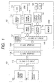
- Fig. 1 is a block diagram showing the structure of an electronic image pickup apparatus according to the first embodiment of the invention.
- Fig. 1 shows the structures of a camera main body 102 and a media card 101 mounted on the camera main body 102.
- the media card 102 has the size and shape similar to a memory card, and mounted on the camera main body 102 in place of a memory card.
- reference numeral 101 represents the media card
- reference numeral 102 represents the camera main body 102.
- a communication circuit 103 executes a control program for wireless communications, for example.
- a nonvolatile memory 104 is made of, for example, a flash memory and stores captured image data.
- An IC card interface circuit 112 is used for data transfer to and from the camera main body 102.
- a control circuit 105 controls various operations, the control contents being described later with reference to Figs. 2 to 11.
- Reference symbol 105M represents a memory.
- An IC card interface 106 is used for data transfer to and from the media card 101.
- a buffer memory 107 temporarily stores image data after the coding process by a CODEC 111.
- a display/switch control circuit 108 controls various switches 109 of the camera main body 102 and a liquid crystal display device (hereinafter called an "LCD") 110.
- the switches 109 includes a capture switch for instructing to capture an image, a menu switch for instructing to display a menu, and other switches.
- the liquid crystal display device (LCD) 110 is used for determining an image to be captured by a user or checking an already captured image.
- the image CODEC 111 processes image data, such as a compression and coding process and an encoding process, e.g., JPEG or the like.
- An imaging circuit 113 controls an optical system such as a zoom lens 115 and converts an image signal supplied from a photoelectric conversion device CCD 116 into image data, upon reception of an instruction from the control circuit 105.
- a frame memory 114 stores non-compressed image data generated by the imaging circuit 113.
- An IC card interface 106A is connected to the media card 101 which can be removably mounted on the camera main body.
- An IC card interface 112A has the function similar to the IC card interface 106A.
- Fig. 2 is a state transition diagram showing the transition between various process states of the control circuit 105 of the camera main body 102 shown in Fig. 1.
- a standby state 201 is a state in which the control circuit 105 stands by until a user enters an operation instruction after the power is turned on and the initialization process is completed.
- a menu selection state 202 is a state in which the control circuit 105 stands by until one of menu items is selected which items are representative of various functions of the camera main body 102 and are displayed when a user turns on the menu switch among the various switches 109 of the camera main body 102.
- a communication control state 203 is a state which is transited when "communication" is selected from the displayed menu.
- a capture processed image confirmation state 204 is a state which is transited when the capture switch among various switches 109 is turned on after the "communication" is selected. Image data captured in this state 204 is encoded and temporarily stored in the buffer memory 107, and at the same time a captured image is displayed for confirmation.
- a data transmission/storage process state 205 is a state in which the image data temporarily stored in the buffer memory 107 is transmitted to the media card 101, transmitted to the external via the communication circuit 103 and stored in the nonvolatile memory 104, after "transmission instruction" is issued.
- Various process states of the control circuit 105 also include an image capture process state 206, a data storage process state 207 and the like during the normal capture process while the transmission process is not executed.
- Fig. 3 is a flow chart illustrating the process to be executed by the control circuit 105 in the standby state 201.
- Fig. 4 is a flow chart illustrating the process to be executed by the control circuit 105 in the menu selection state 202.
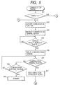
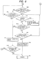
- Figs. 5 and 6 are flow charts illustrating the process to be executed by the control circuit 105 in the communication control circuit 203.
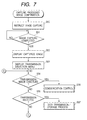
- Figs. 7 and 8 are flow charts illustrating the process to be executed by the control circuit 105 in the capture processed image confirmation state 204.
- Fig. 9 is a flow chart illustrating the process to be executed by the control circuit 105 in the data transmission/storage process state 205.
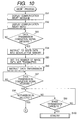
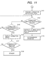
- Figs. 10 and 11 are flow charts illustrating the process to be executed by the control circuit 105 in an abort process.
- the control circuit 105 operates in accordance with the flow charts shown in Figs. 3 to 11.
- the flow charts of Figs. 3 to 11 illustrate a portion of a program stored in the memory 105M.
- the control circuit 105 is a computer which operates by reading this program from the memory 105M.
- the memory 105M is a storage medium storing this program capable of being read by the control circuit 105.
- This program is stored in the IC card and the control circuit 105 reads the program from the IC card via the IC card interface circuit 106.
- the IC card corresponds to a storage medium storing this program capable of being read by the control circuit.
- This program may be supplied externally to the control circuit 105 via the communication circuit 103.
- the control circuit 105 initializes the camera main body 102 to transit to the standby state 201 (Fig. 3). Thereafter, as the user depresses the capture switch among the various switches 109 (YES at S1), the control circuit 105 judges that the user wishes the ordinary image capture operation, and transits to the image capture state 206 (Fig. 2) (S5).
- the control circuit issues an image capture instruction to the imaging circuit 113.
- the imaging circuit 113 performs an imaging process by using an image signal supplied from CCD 116, and stores image data in the frame memory 114.
- the control circuit 105 issues a compression/coding instruction for the image data to the image CODEC 111.
- the image CODEC 111 executes a conversion process for the image data.
- the coded image data is temporarily stored in the buffer memory 107 via the IC card interface circuit 106, and a process completion is notified to the control circuit 105.
- the control circuit 105 transits to the data storage process state 207 (Fig. 2).
- the data storage process state 207 information of a file name, storage date and time and the like is written in the nonvolatile memory 104 of the media card 101. Thereafter, the coded image data is read from the buffer memory 107 and transmitted to and written in the nonvolatile memory 104 via the IC card interface circuit 106. Thereafter, the state transits to the standby state 201 in which the control circuit stands by until a new user's operation is entered.
- the menu selection state 202 the menu including menu items such as an image capture mode, an image deletion and communication is displayed on the display device 110, and the control circuit stands by until one of the menu items is selected.
- the function of the media card 101 is checked (S11). If the media card 101 has a communication function (YES at S12), a communication menu is displayed as valid (S13), whereas if the media card 101 has no communication function (NO at S12), the communication menu is displayed as invalid (S14).
- the communication menu is displayed thick on the display device 110 and when the communication menu is selected by the switch 109, the communication control is executed.
- the communication menu is displayed thin on the display device 110 and the communication menu cannot be selected by the switch 109 (or even if it is selected, the communication control is not executed).
- the control circuit 105 transits to the communication control state 203 (S20, Fig. 5).
- the menu selection state 202 if a menu other than the communication menu is selected (S17), a menu selection process is performed (S21), whereas if the menu selection state is canceled (S18), the state returns to the standby state 201 (S19).
- the communication control state 203 since a connection is not still established relative to the communication partner (NO at S31), first the communication function is checked (S32) and the communication circuit 103 of the media card 101 is instructed to detect a communication terminal capable of wireless communications in a communication area (S33). Upon reception of this instruction, the communication circuit 103 returns the information on whether a registered partner is detected, to the control circuit 105 if the communication partner is registered beforehand, whereas if not, the communication circuit performs a search operation for a terminal capable of wireless communications in the communication area and returns the information of all communication terminals responded to the search operation to the control circuit 105.
- control circuit 105 If there is a response to the search (YES at S34), the control circuit 105 received this information sends it to LCD 110 via the display/switch control circuit 108 to display this information (S35). The control circuit stands by until the user selects a communication partner.
- the control circuit 105 sends a connection instruction signal to the communication circuit 103 of the media card 101 (S37).
- the communication circuit 103 received the connection instruction signal at step S37 establishes a connection in response to the connection instruction signal, and sends a connection completion notification to the control circuit 105.
- the control circuit 105 stands by until a connection completion is notified from the media card 101 (S42) or a connection error is notified from the media card 101 (S43).
- the control circuit 105 stands by until the image capture switch among the switches 109 is depressed (S40), and a connection error is notified from the media card 101, or the communication selection is canceled by the switch 109 (S45).
- the display/switch control circuit 108 sends an image capture instruction to the control circuit 105.
- the control circuit 105 transits to the capture processed image confirmation state 204 (S41, Fig. 7).
- the control circuit 105 instructs the communication circuit 103 to send a disconnection instruction signal to the communication partner (S46). If the connection error is notified at S43 or S431, the connection error is displayed on the display device 110 (S44), and if a connection reestablishment is instructed by the switch 109 (S441), the flow returns to S32.
- the control circuit 105 sends an image capture instruction to the imaging circuit 113 (S50). Upon reception of this instruction, the imaging circuit 113 performs an operation of capturing a series of image data. After the image data is captured in the frame memory 114 (YES at S51), the control circuit 105 reads the image data stored in the frame memory 114 and instructs the display/switch control circuit 108 to display the image data on LCD 110 (S52). A transmission selection menu is displayed on LCD 110 (S53).
- this image can be cancelled by using the switch 109.
- the control circuit 105 receives this cancel instruction signal from the display/switch control circuit 108 (YES at S54), the control circuit 105 transits to the communication control state 203 (S55) and the flow advances from YES at S31 shown in Fig. 5 to S40 whereat the control circuit stands by until the image capture switch is newly depressed.
- Step S52 If a user checks the captured image displayed at Step S52 and wishes to transmit this captured image, the user operates the switch 109 to select "transmission instruction" in the menu displayed on LCD 110 (YES at S56).
- the control circuit 105 transits to the data transmission/storage state 205 (S57, Fig. 9).
- control circuit 105 In the data transmission/storage state 205, first the control circuit 105 writes information of the file name, storage date and time and the like in the nonvolatile memory 104 of the media card 101 (S71), and then outputs an instruction signal to the IC card interface circuit 112 of the media card 101 to supply the image data to the communication circuit 103 and nonvolatile memory 104 (S72).
- a communication packet header (transmission packet header) is generated (S74) and a data transmission number (length) is set to the IC card interface circuit 106 of the camera main body 102 (S75), and the communication packet header is written in the IC card interface circuit 112 of the media card 101 (S76).
- the IC card interface circuit 106 is given an instruction to transmit the image data corresponding to the length indicated in the header from the buffer memory 107 to the media card 101 (S77).
- the IC card interface circuit 106 Upon reception of this instruction, the IC card interface circuit 106 transmits the image data corresponding to the length indicated by the instruction from the buffer memory 107 to the media card 101. When the transmission is completed, a transmission completion signal is output to the control circuit 105. Upon reception of this transmission completion signal, the control circuit 105 advances to the next Step (YES at S908).
- the IC card interface circuit 112 of the media card 101 Upon reception of the header of the communication data, the IC card interface circuit 112 of the media card 101 transmits only the header information to the communication circuit 103, and thereafter transmits the image data corresponding to each length to the communication circuit 103 and nonvolatile memory 104 at the same time.
- the communication circuit 103 transmits the packet including the transmitted header information and image data corresponding to the length to the external, for example, in a wireless communication frequency band.
- control circuit 105 terminates a series of communication controls and transits to the standby state 201 (S913). If the communication with the communication partner 103 is disconnected during the transmission of image data (S909), an abort process is performed (S910).
- connection establishment is performed by the processes at Steps S31 to S37 shown in Fig. 5. If a connection instruction is sent from the control circuit 105 to the communication circuit 103 (S37 in Fig. 5), the connection circuit 103 performs a connection establishment with a communication partner in accordance with the instruction. However, if the new connection cannot be established because the instructed communication partner is already communicating with another terminal or the communication partner does not exist in the communication area, then the communication circuit 103 sends a connection establishment error display signal (connection error notification) to the control circuit 105.
- connection establishment error display signal connection error notification
- the control circuit 105 Upon reception of this signal (NO at S42 in Fig. 6, YES at S43), the control circuit 105 instructs the display/switch control circuit 108 to display a communication connection error message on LCD 110 (S44). The user looking at this message selects either a connection reestablishment instruction or a cancel instruction by operating the switch 109. In accordance with this selected instruction, the control circuit 105 sends an operation instruction signal to the communication circuit 103.
- the communication circuit 103 sends a connection error notification signal to the control circuit 105.
- the control circuit 105 also performs the process at S44 when this connection error notification is received (S431).
- the control circuit 105 receives a communication connection error notification (YES at S58 in Fig. 7) and makes a communication connection error message to be displayed on LCD 110 (S59) and an image storage selection menu to be displayed on LCD 110 (S60). If the user selects the image storage selection menu (YES at S61), the control circuit 105 transits from the capture processed image confirmation state 204 to the data storage process 207 (S62), and after a series of ordinary image storage processes is executed, the state transits to the standby state 201.
- the communication circuit 103 sends a communication abort error message signal to the control circuit 105.
- the control circuit 105 Upon reception of this signal (YES at S909 in Fig. 9), the control circuit 105 performs an abort process (S910), and as shown in Fig. 10, makes the display/switch control circuit 108 to display a communication abort error message on LCD 110 (S91) and an abort process menu error on LCD 110 (S92).
- the transmission state of the image data is confirmed. In this case, if it is waited for a data transmission completion signal to be transmitted from the IC card interface circuit 106 of the camera main body 102, the operation stands by until this signal is received.
- the control circuit 105 Upon reception of the data transmission completion signal (YES at S93), the control circuit 105 instructs the IC card interface circuit 112 of the media card 101 to transmit image data only to the nonvolatile memory 104 (S94), and thereafter supplies the IC card interface circuit 106 of the camera main body 102 with the length information (transmission number) of the image data still not transmitted (S95) to transmit all the remaining image data to the nonvolatile memory 104 (S96).
- the IC card interface circuit 106 After the transmission completion of the remaining image data, the IC card interface circuit 106 outputs a data transmission completion signal (S97).
- the IC card interface circuit 112 of the media card 101 received the data transmission instruction only to the nonvolatile memory 104 transmits the received image data to the nonvolatile memory 104.
- the user confirmed the communication abort message selects either the data retransmission or the cancel of data transmission by operating the switch 109. If the retransmission is selected (YES at S98), the control circuit 105 again outputs a connection instruction to the communication circuit 103 (S101) and stands by until the connection completion notification is transmitted from the communication circuit 103.
- control circuit 105 Upon reception of the connection completion notification (YES at S102), the control circuit 105 sends an instruction signal for writing image data in the communication circuit 103, to the IC card interface circuit 112 of the media card 101 (S103), and a retransmission operation is performed (S104, S73 in Fig. 9).
- a communication packet header is generated (S74), a data transmission number (length) is set to the IC card interface circuit 106 of the camera main body 102 (S75), and the communication packet header is written in the IC card interface circuit 112 of the media circuit 101 (S76).
- An instruction to transmit the image data corresponding to the length indicated by the header from the buffer memory 107 to the media card 101 is supplied to the IC card interface circuit 106 of the camera main body 102 (S77).
- the IC card interface circuit 112 of the media card 101 Upon reception of the instruction to write the image data in the communication circuit 103, the IC card interface circuit 112 of the media card 101 transmits the header information to the communication circuit 103 and transmits the image data succeedingly transmitted to the communication circuit 103.
- the IC card interface circuits 106 and 112 and communication circuit 103 perform a series of data transmission operations described earlier until the retransmission of the image data is completed.
- connection establishment timing is not limited thereto but it may be set after the image data is selected and a transmission instruction is received.
- the structure of the second embodiment is fundamentally the same as that of the first embodiment. Therefore, in the description of the second embodiment, the description given for the structure of the first embodiment will be used.
- a communication circuit 103A is provided in a camera main body 130.
- This communication circuit 103A has a similar function to that of the communication circuit 103 described above.
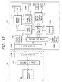
- Fig. 12 is a block diagram showing the structure of an image pickup apparatus in which the communication circuit 103A is provided in the camera main body 130.
- like elements to those of the first embodiment are represented by identical reference numerals and the description thereof is omitted.
- the communication circuit 103A is provided not in the media card 120 but in the camera main body 130.
- control circuit 105 executes an initialization process similar to the first embodiment and transits to the standby state 201 (Fig. 3) to wait for a user's operation input.
- the control circuit 105 transits to the menu selection state 202 (S6).
- the communication function of the communication circuit 103A built in the camera main body 130 is displayed in the menu screen of LCD 110, and the function of the media card 101 or 120 mounted on the camera main body 130 is checked (S11). If the media card has a communication function, this function is displayed in the menu screen.
- the user selects one of communication functions displayed in the menu screen to decide whether the communication function built in the camera main body is used or the communication function of the media card is used. If the user selects the communication function of the media card, the operation similar to the first embodiment is performed.
- the control circuit 105 transits to the communication control state 203 (Fig. 5), performs a search display of communication terminals, and if a communication partner capable of communications is selected, a connection is established (S31 to S37 in Fig. 5, S42 in Fig. 6).
- the control circuit 105 transits to the capture processed image confirmation state 204 (S41, Fig. 7) to execute the operation of capturing image data in the buffer memory 107 and maintains the capture processed image confirmation state 204 until the user selects an image data transmission by operating the switch 109 (S51 to S56 in Fig. 7).
- control circuit 105 transits to the data transmission/storage process state 205 (S57, Fig. 9).
- the control circuit instructs to write image data in the media card 120 and communication circuit 103A (S72).
- a communication packet header to be used by the communication circuit 103A is generated (S74), and the data length capable of transmitting from the communication circuit 103A at a time is set to the IC card interface circuit 106 of the camera main body 130 as a transmission number (S75).
- the communication packet header is transmitted (S76) and a transmission instruction signal is supplied to the IC card interface circuit 106 of the camera main body 130 (S77).
- the IC card interface circuit 106 Upon reception of this instruction, the IC card interface circuit 106 transmits the image data corresponding to the length indicated by the instruction, from the buffer memory 107 to the communication circuit 103A and IC card interface circuit 112, and after the transmission is completed, a transmission completion signal is sent to the control circuit 105.
- the communication circuit 103A of the camera main body 130 transmits the image data from the buffer memory 107 to the communication partner, whereas the IC card interface circuit 112 of the media card 120 transmits the transmitted image data to the nonvolatile memory 104 to be stored therein.
- control circuit 105 terminates a series of communication controls and transits to the standby state 201 (S82).
- the communication circuit 103A sends a communication abort error message signal to the control circuit 105 (S80).
- the control circuit 105 Upon reception of this communication abort error message signal, as shown in Fig. 10, the control circuit 105 instructs the display/switch control circuit 108 to display a communication abort error message on LCD 110 (S91), and confirms the transmission state of the image data. In this case, if it is waited for the transfer completion signal to be transmitted from the IC card interface circuit 106 of the camera main body 130, the control circuit stands by until this signal is received.
- the control circuit 105 Upon reception of the data transmission completion signal (YES at S93), the control circuit 105 instructs the IC card interface circuit 106 of the camera main body 130 to transmit image data only to the nonvolatile memory 104 (S94), and thereafter outputs the length information of the image data still not transmitted (S95) to transmit all the remaining image data to the nonvolatile memory 104 (S96).
- the user confirmed the communication abort message selects either the data retransmission or the cancel of data transmission by operating the switch 109. If the retransmission is selected (YES at S98), the control circuit 105 again outputs a connection instruction to the communication circuit 103A (S101) and stands by until the connection completion notification is transmitted from the communication circuit 103A.
- the control circuit 105 Upon reception of the connection completion notification (YES at S102), the control circuit 105 sends an instruction signal for transmitting the image data only to the communication circuit 103A (S103), transmits the header information to the communication circuit 103A, and sends an instruction to transmit the image data corresponding to the length indicated by the header from the buffer memory 107, to the IC card interface circuit 106 of the camera main body 130 to start transmitting the image data (S104, S73 in Fig. 9).
- the communication circuit 103A performs a series of data transfer operations described earlier until the retransmission of the image data is completed.
- connection establishment timing is not limited thereto but it may be set after the image data is selected and a transmission instruction is received.
- image data is automatically stored in the nonvolatile memory 104 during the communication operation. Instead, a menu item of not storing image data may be provided, and if a user selects this item, the image data is not stored in the nonvolatile memory 104.
- the control circuit 105 transits to the standby state 201 after the communication operation, as shown at Step S913 of Fig. 5.
- the control circuit may transit to the menu selection state 202 or communication control state 203 after the communication operation to thereby continue the communication operation unless it is canceled.
- a portion or the whole of the process of realizing the function of each of the embodiments may be performed by an OS or the like running on a computer.
- the embodiments of the invention described with reference to the drawings comprise an electronic image pickup apparatus and processes performed therein, the invention also extends to computer programs on or in a carrier, adapted for putting the invention into practice.
- the program may be in the form of source or object code or in any other form suitable for use in the implementation of the relevant processes.
- the carrier be any entity or device carrying the program.
- the carrier may comprise a storage medium, such as a ROM, for example a CD ROM or a semiconductor ROM, or a magnetic recording medium, for example a floppy disc or hard disc.
- a storage medium such as a ROM, for example a CD ROM or a semiconductor ROM, or a magnetic recording medium, for example a floppy disc or hard disc.
- the carrier may be a transmissible carrier such as an electrical or optical signal which may be conveyed via electrical or optical cable or by radio or other means.
- the carrier When a program is embodied in a signal which may be conveyed directly by a cable or other device or means, the carrier may be constituted by such cable or other device or means.
- the carrier may be an integrated circuit in which the program is embedded, the integrated circuit being adapted for performing, or for use in the performance of, the relevant processes.
Landscapes
- Engineering & Computer Science (AREA)
- Multimedia (AREA)
- Signal Processing (AREA)
- Studio Devices (AREA)
- Facsimiles In General (AREA)
- Telephonic Communication Services (AREA)
- Television Signal Processing For Recording (AREA)
Abstract
Description
Claims (26)
- An image pickup apparatus comprising:wherein the memory is provided in the card.connection means (106A) for connecting a card; andtransferring means (105, 106) for transferring captured image data to transmission means and a memory when the captured image data is transmitted from the transmission means,
- An image pickup apparatus according to claim 1, wherein said transferring means transfers the image data to the transmission means (103) provided in the card.
- An image pickup apparatus according to claim 1, wherein said transferring means transfers the image data to the transmission means (103A) provided in the image pickup apparatus.
- An image pickup apparatus according to claim 1, wherein said transferring means transfers the image data corresponding to a data length of a transmission packet to the transmission means and the memory.
- An image pickup apparatus according to claim 1, wherein said transferring means repeats a header transfer process and an image data process until the transfer of the image data is completed, in the header transfer process, a header of a transmission packet is transferred to the transmission means, and in the image data transfer process, the image data corresponding to a data length of the transmission packet is transferred to the transmission means and the memory.
- An image pickup apparatus according to claim 1, wherein said transferring means writes a file name of the image data in the memory, and thereafter repeats a transfer process of transferring a header of a transmission packet to the transmission means and a transfer process of transferring the image data corresponding to a data length to the transmission means and the memory, until the transfer of the image data is completed.
- An image pickup apparatus according to claim 4, wherein said transferring means transfers the image data still not transferred to the memory, when transmission is aborted.
- An image pickup apparatus according to claim 4, wherein said transferring means transfers the image data still not transferred to the memory without partitioning the image data by the data length of the transmission packet, when transmission is aborted.
- A method of transferring image data of an image pickup apparatus having connection means for connecting a card, comprising steps of:wherein the memory is provided in the card.taking an image and generating image data (S50); andwhen the generated image data is transmitted from transmitting means, transferring the image data to the transmission means and a memory (S77),
- A method according to claim 9, wherein said transferring step transfers the image data to the transmission means provided in the card.
- A method according to claim 9, wherein said transferring step transfers the image data to the transmission means provided in the image pickup apparatus.
- A method according to claim 9, wherein said transferring step transfers the image data corresponding to a data length of a transmission packet to the transmission means and the memory.
- A method according to claim 9, wherein said transferring step repeats (S911) a header transfer process (S76) and an image data process (S77) until the transfer of the image data is completed, in the header transfer process, a header of a transmission packet is transferred to the transmission means, and in the image data transfer process, the image data corresponding to a data length of the transmission packet is transferred to the transmission means and the memory.
- A method according to claim 9, wherein said transferring step writes a file name of the image data in the memory (S71), and thereafter repeats a transfer process (S76) of transferring a header of a transmission packet to the transmission means and a transfer process (S77) of transferring the image data corresponding to a data length to the transmission means and the memory, until the transfer of the image data is completed.
- A method according to claim 12, wherein said transferring step transfers the image data still not transferred to the memory (S96), when transmission is aborted (S909).
- A method according to claim 12, wherein said transferring step transfers the image data still not transferred to the memory without partitioning the image data by the data length of the transmission packet (S96), when transmission is aborted (S909).
- A program instruction carrier medium carrying instructions for causing a programmable image pickup apparatus to become operable to transfer generated image data to transmission means and a memory, wherein the memory is provided in a separate card.
- A program instruction carrier medium according to claim 17, wherein said transferring step transfers the image data to the transmission means provided in the card.
- A program instruction carrier medium according to claim 17, wherein said transferring step transfers the image data to the transmission means provided in the image pickup apparatus.
- A program instruction carrier medium according to claim 17, wherein said transferring step transfers the image data corresponding to a data length of a transmission packet to the transmission means and the memory.
- A program instruction carrier medium according to claim 17, wherein said transferring step repeats (S911) a header transfer process (S76) and an image data process (S77) until the transfer of the image data is completed, in the header transfer process, a header of a transmission packet is transferred to the transmission means, and in the image data transfer process, the image data corresponding to a data length of the transmission packet is transferred to the transmission means and the memory.
- A program instruction carrier medium according to claim 17, wherein said transferring step writes a file name of the image data in the memory (S71), and thereafter repeats a transfer process (S76) of transferring a header of a transmission packet to the transmission means and a transfer process (S77) of transferring the image data corresponding to a data length to the transmission means and the memory, until the transfer of the image data is completed.
- A program instruction carrier medium according to claim 20, wherein said transferring step transfers the image data still not transferred to the memory (S96), when transmission is aborted (S909).
- A program instruction carrier medium according to claim 20, wherein said transferring step transfers the image data still not transferred to the memory without partitioning the image data by the data length of the transmission packet (S96), when transmission is aborted (S909).
- A program instruction carrier medium according to any of claims 17 to 24, when embodied as a data storage device storing the instructions.
- A program instruction carrier medium according to any of claims 17 to 24, when embodied as a signal carrying the instructions.
Applications Claiming Priority (2)
| Application Number | Priority Date | Filing Date | Title |
|---|---|---|---|
| JP2000276728A JP3599654B2 (en) | 2000-09-12 | 2000-09-12 | How to send and save image data |
| JP2000276728 | 2000-09-12 |
Publications (3)
| Publication Number | Publication Date |
|---|---|
| EP1187450A2 true EP1187450A2 (en) | 2002-03-13 |
| EP1187450A3 EP1187450A3 (en) | 2004-09-15 |
| EP1187450B1 EP1187450B1 (en) | 2007-12-05 |
Family
ID=18762150
Family Applications (1)
| Application Number | Title | Priority Date | Filing Date |
|---|---|---|---|
| EP01307768A Expired - Lifetime EP1187450B1 (en) | 2000-09-12 | 2001-09-12 | Image pickup apparatus |
Country Status (4)
| Country | Link |
|---|---|
| US (1) | US7071975B2 (en) |
| EP (1) | EP1187450B1 (en) |
| JP (1) | JP3599654B2 (en) |
| DE (1) | DE60131715T2 (en) |
Cited By (1)
| Publication number | Priority date | Publication date | Assignee | Title |
|---|---|---|---|---|
| EP2341444A1 (en) * | 2009-12-17 | 2011-07-06 | Canon Kabushiki Kaisha | Data recording apparatus and method |
Families Citing this family (9)
| Publication number | Priority date | Publication date | Assignee | Title |
|---|---|---|---|---|
| JP3599654B2 (en) * | 2000-09-12 | 2004-12-08 | キヤノン株式会社 | How to send and save image data |
| US6753873B2 (en) * | 2001-01-31 | 2004-06-22 | General Electric Company | Shared memory control between detector framing node and processor |
| US8037229B2 (en) | 2002-11-21 | 2011-10-11 | Sandisk Technologies Inc. | Combination non-volatile memory and input-output card with direct memory access |
| US20050055479A1 (en) * | 2002-11-21 | 2005-03-10 | Aviad Zer | Multi-module circuit card with inter-module direct memory access |
| US7209995B2 (en) * | 2003-12-09 | 2007-04-24 | Sandisk Corporation | Efficient connection between modules of removable electronic circuit cards |
| US7702821B2 (en) | 2005-09-15 | 2010-04-20 | Eye-Fi, Inc. | Content-aware digital media storage device and methods of using the same |
| FI8511U1 (en) * | 2009-07-09 | 2009-11-07 | Cyberncam Technology Ltd Oy | Optional camera equipment |
| JP5317872B2 (en) * | 2009-07-15 | 2013-10-16 | キヤノン株式会社 | Imaging apparatus, control method thereof, and program |
| JP5629468B2 (en) * | 2010-01-15 | 2014-11-19 | キヤノン株式会社 | Information processing apparatus and control method thereof |
Family Cites Families (22)
| Publication number | Priority date | Publication date | Assignee | Title |
|---|---|---|---|---|
| JPH04170881A (en) * | 1990-11-05 | 1992-06-18 | Ricoh Co Ltd | Image wireless transmission device |
| JP3548191B2 (en) * | 1993-03-22 | 2004-07-28 | キヤノン株式会社 | camera |
| US5561458A (en) * | 1994-01-28 | 1996-10-01 | Polaroid Corporation | Electronic imaging module for reversibly converting a photographic camera into an electronic imaging camera |
| US5640202A (en) * | 1994-04-26 | 1997-06-17 | Canon Kabushiki Kaisha | Imaging system which changes the frame rate of the image signal |
| JP3893480B2 (en) * | 1994-09-28 | 2007-03-14 | 株式会社リコー | Digital electronic camera |
| JP3525353B2 (en) | 1994-09-28 | 2004-05-10 | 株式会社リコー | Digital electronic still camera |
| US5815205A (en) * | 1995-02-21 | 1998-09-29 | Ricoh Company, Ltd. | External communication interface for a digital camera |
| JPH0916735A (en) | 1995-06-26 | 1997-01-17 | Mitsubishi Electric Corp | PC card |
| JP3739446B2 (en) | 1995-09-13 | 2006-01-25 | オリンパス株式会社 | camera |
| US5790193A (en) * | 1995-11-22 | 1998-08-04 | Eastman Kodak Company | Accessory module for an electronic camera |
| US6891567B2 (en) * | 1998-06-26 | 2005-05-10 | Fotonation Holdings, Llc | Camera messaging and advertisement system |
| JP3631838B2 (en) * | 1996-02-21 | 2005-03-23 | チノン株式会社 | External storage device and camera system |
| US6005613A (en) * | 1996-09-12 | 1999-12-21 | Eastman Kodak Company | Multi-mode digital camera with computer interface using data packets combining image and mode data |
| US5917542A (en) * | 1997-02-18 | 1999-06-29 | Eastman Kodak Company | System and method for digital image capture and transmission |
| JP3634546B2 (en) * | 1997-03-28 | 2005-03-30 | キヤノン株式会社 | Imaging device |
| JP3492149B2 (en) * | 1997-05-09 | 2004-02-03 | 京セラ株式会社 | Wireless communication terminal device, wireless communication terminal used for the wireless communication terminal device, and digital camera |
| JPH1173247A (en) * | 1997-06-27 | 1999-03-16 | Canon Inc | I / O card, electronic device, electronic system, and method of starting electronic device |
| FI116957B (en) * | 1998-10-29 | 2006-04-13 | Nokia Corp | Method for data transfer between mobile communicator and special device and a data transfer device |
| KR100350607B1 (en) * | 1999-03-31 | 2002-08-28 | 삼성전자 주식회사 | Portable composite communication terminal for transmitting/receiving voice and picture data, and operating method and communication system therefor |
| JP2000341616A (en) | 1999-05-31 | 2000-12-08 | Olympus Optical Co Ltd | Electronic camera device |
| JP2002094928A (en) * | 2000-09-11 | 2002-03-29 | Canon Inc | Image recording apparatus, image data communication processing method, and storage medium |
| JP3599654B2 (en) * | 2000-09-12 | 2004-12-08 | キヤノン株式会社 | How to send and save image data |
-
2000
- 2000-09-12 JP JP2000276728A patent/JP3599654B2/en not_active Expired - Fee Related
-
2001
- 2001-09-07 US US09/947,357 patent/US7071975B2/en not_active Expired - Lifetime
- 2001-09-12 DE DE60131715T patent/DE60131715T2/en not_active Expired - Lifetime
- 2001-09-12 EP EP01307768A patent/EP1187450B1/en not_active Expired - Lifetime
Cited By (5)
| Publication number | Priority date | Publication date | Assignee | Title |
|---|---|---|---|---|
| EP2341444A1 (en) * | 2009-12-17 | 2011-07-06 | Canon Kabushiki Kaisha | Data recording apparatus and method |
| CN102157172A (en) * | 2009-12-17 | 2011-08-17 | 佳能株式会社 | Data recording apparatus and control method thereof |
| US8225010B2 (en) | 2009-12-17 | 2012-07-17 | Canon Kabushiki Kaisha | Data recording apparatus and method |
| US8533371B2 (en) | 2009-12-17 | 2013-09-10 | Canon Kabushiki Kaisha | Data recording apparatus and method |
| CN102157172B (en) * | 2009-12-17 | 2015-03-04 | 佳能株式会社 | Data recording apparatus and control method thereof |
Also Published As
| Publication number | Publication date |
|---|---|
| DE60131715D1 (en) | 2008-01-17 |
| EP1187450B1 (en) | 2007-12-05 |
| JP2002094926A (en) | 2002-03-29 |
| DE60131715T2 (en) | 2008-11-06 |
| JP3599654B2 (en) | 2004-12-08 |
| US20020030752A1 (en) | 2002-03-14 |
| EP1187450A3 (en) | 2004-09-15 |
| US7071975B2 (en) | 2006-07-04 |
Similar Documents
| Publication | Publication Date | Title |
|---|---|---|
| US7477880B2 (en) | Communication device, image-pickup device, storage medium and communication method | |
| EP1187450B1 (en) | Image pickup apparatus | |
| JP4174208B2 (en) | Information processing terminal and information processing method | |
| US7796165B2 (en) | Image capturing apparatus and image capturing method | |
| JP2002092543A (en) | Code reader, recording medium, electronic device, data transmission / reception system, and data transmission / reception method | |
| US7612922B2 (en) | Image-sensing method and apparatus, control method and apparatus therefor, and storage medium | |
| US7139021B2 (en) | Image input apparatus that can transmit input image | |
| JP3706824B2 (en) | Image data transmission method, communication apparatus, image data transmission program, and storage medium | |
| JP4262534B2 (en) | Digital equipment | |
| JPH05153453A (en) | Recording and reproducing device incorporating communication means | |
| US8154603B2 (en) | Imaging device transferring data to external device | |
| JP2005167695A (en) | Electronic imaging device | |
| JP3899774B2 (en) | Imaging device | |
| JP2004185235A (en) | Electronic equipment and control program downloading method for electronic equipment | |
| JP2004088481A (en) | Camera device and control method thereof | |
| JP4720867B2 (en) | Image display system | |
| JP3419828B2 (en) | Image communication adapter device | |
| JP3839495B2 (en) | Electronic camera and playback device | |
| JP2002009996A (en) | Facsimile machine | |
| JP2008147891A (en) | Digital camera | |
| JP4076337B2 (en) | Information equipment system | |
| JP3597528B2 (en) | Electronic camera | |
| JP3548527B2 (en) | Electronic imaging device | |
| JP2000253290A (en) | Digital camera | |
| JP2002094925A (en) | Imaging device with communication function, control method therefor, and storage medium |
Legal Events
| Date | Code | Title | Description |
|---|---|---|---|
| PUAI | Public reference made under article 153(3) epc to a published international application that has entered the european phase |
Free format text: ORIGINAL CODE: 0009012 |
|
| AK | Designated contracting states |
Kind code of ref document: A2 Designated state(s): AT BE CH CY DE DK ES FI FR GB GR IE IT LI LU MC NL PT SE TR |
|
| AX | Request for extension of the european patent |
Free format text: AL;LT;LV;MK;RO;SI |
|
| PUAL | Search report despatched |
Free format text: ORIGINAL CODE: 0009013 |
|
| AK | Designated contracting states |
Kind code of ref document: A3 Designated state(s): AT BE CH CY DE DK ES FI FR GB GR IE IT LI LU MC NL PT SE TR |
|
| AX | Request for extension of the european patent |
Extension state: AL LT LV MK RO SI |
|
| 17P | Request for examination filed |
Effective date: 20050131 |
|
| AKX | Designation fees paid |
Designated state(s): DE FI FR GB SE |
|
| 17Q | First examination report despatched |
Effective date: 20051115 |
|
| GRAP | Despatch of communication of intention to grant a patent |
Free format text: ORIGINAL CODE: EPIDOSNIGR1 |
|
| GRAS | Grant fee paid |
Free format text: ORIGINAL CODE: EPIDOSNIGR3 |
|
| GRAA | (expected) grant |
Free format text: ORIGINAL CODE: 0009210 |
|
| AK | Designated contracting states |
Kind code of ref document: B1 Designated state(s): DE FI FR GB SE |
|
| REG | Reference to a national code |
Ref country code: GB Ref legal event code: FG4D |
|
| REF | Corresponds to: |
Ref document number: 60131715 Country of ref document: DE Date of ref document: 20080117 Kind code of ref document: P |
|
| PG25 | Lapsed in a contracting state [announced via postgrant information from national office to epo] |
Ref country code: SE Free format text: LAPSE BECAUSE OF FAILURE TO SUBMIT A TRANSLATION OF THE DESCRIPTION OR TO PAY THE FEE WITHIN THE PRESCRIBED TIME-LIMIT Effective date: 20080305 |
|
| ET | Fr: translation filed | ||
| PLBE | No opposition filed within time limit |
Free format text: ORIGINAL CODE: 0009261 |
|
| STAA | Information on the status of an ep patent application or granted ep patent |
Free format text: STATUS: NO OPPOSITION FILED WITHIN TIME LIMIT |
|
| 26N | No opposition filed |
Effective date: 20080908 |
|
| PGFP | Annual fee paid to national office [announced via postgrant information from national office to epo] |
Ref country code: FI Payment date: 20140901 Year of fee payment: 14 |
|
| PGFP | Annual fee paid to national office [announced via postgrant information from national office to epo] |
Ref country code: FR Payment date: 20140924 Year of fee payment: 14 |
|
| PG25 | Lapsed in a contracting state [announced via postgrant information from national office to epo] |
Ref country code: FI Free format text: LAPSE BECAUSE OF NON-PAYMENT OF DUE FEES Effective date: 20150912 |
|
| REG | Reference to a national code |
Ref country code: FR Ref legal event code: ST Effective date: 20160531 |
|
| PG25 | Lapsed in a contracting state [announced via postgrant information from national office to epo] |
Ref country code: FR Free format text: LAPSE BECAUSE OF NON-PAYMENT OF DUE FEES Effective date: 20150930 |
|
| PGFP | Annual fee paid to national office [announced via postgrant information from national office to epo] |
Ref country code: GB Payment date: 20170929 Year of fee payment: 17 |
|
| GBPC | Gb: european patent ceased through non-payment of renewal fee |
Effective date: 20180912 |
|
| PG25 | Lapsed in a contracting state [announced via postgrant information from national office to epo] |
Ref country code: GB Free format text: LAPSE BECAUSE OF NON-PAYMENT OF DUE FEES Effective date: 20180912 |
|
| PGFP | Annual fee paid to national office [announced via postgrant information from national office to epo] |
Ref country code: DE Payment date: 20191129 Year of fee payment: 19 |
|
| REG | Reference to a national code |
Ref country code: DE Ref legal event code: R119 Ref document number: 60131715 Country of ref document: DE |
|
| PG25 | Lapsed in a contracting state [announced via postgrant information from national office to epo] |
Ref country code: DE Free format text: LAPSE BECAUSE OF NON-PAYMENT OF DUE FEES Effective date: 20210401 |