EP1187302B1 - Motor-driven system with toothed stator poles - Google Patents
Motor-driven system with toothed stator poles Download PDFInfo
- Publication number
- EP1187302B1 EP1187302B1 EP01306437A EP01306437A EP1187302B1 EP 1187302 B1 EP1187302 B1 EP 1187302B1 EP 01306437 A EP01306437 A EP 01306437A EP 01306437 A EP01306437 A EP 01306437A EP 1187302 B1 EP1187302 B1 EP 1187302B1
- Authority
- EP
- European Patent Office
- Prior art keywords
- rotor
- motor
- phase
- driven system
- stator
- Prior art date
- Legal status (The legal status is an assumption and is not a legal conclusion. Google has not performed a legal analysis and makes no representation as to the accuracy of the status listed.)
- Expired - Lifetime
Links
- 230000005291 magnetic effect Effects 0.000 claims description 59
- 238000004804 winding Methods 0.000 claims description 13
- 230000005284 excitation Effects 0.000 claims description 6
- 239000000126 substance Substances 0.000 claims description 6
- 230000000052 comparative effect Effects 0.000 description 9
- 239000000470 constituent Substances 0.000 description 5
- 230000014509 gene expression Effects 0.000 description 5
- 238000010586 diagram Methods 0.000 description 4
- 230000004907 flux Effects 0.000 description 4
- 238000000034 method Methods 0.000 description 4
- 230000000694 effects Effects 0.000 description 3
- 239000002184 metal Substances 0.000 description 3
- 239000003302 ferromagnetic material Substances 0.000 description 2
- 230000001939 inductive effect Effects 0.000 description 2
- 230000005405 multipole Effects 0.000 description 2
- 239000011295 pitch Substances 0.000 description 2
- 230000002457 bidirectional effect Effects 0.000 description 1
- 210000000078 claw Anatomy 0.000 description 1
- 239000002131 composite material Substances 0.000 description 1
- 230000007547 defect Effects 0.000 description 1
- 230000003111 delayed effect Effects 0.000 description 1
- 230000001419 dependent effect Effects 0.000 description 1
- 239000000696 magnetic material Substances 0.000 description 1
- 230000005415 magnetization Effects 0.000 description 1
- 230000003287 optical effect Effects 0.000 description 1
- 239000002245 particle Substances 0.000 description 1
- 230000000717 retained effect Effects 0.000 description 1
- 230000001360 synchronised effect Effects 0.000 description 1
Images



Classifications
-
- H—ELECTRICITY
- H02—GENERATION; CONVERSION OR DISTRIBUTION OF ELECTRIC POWER
- H02K—DYNAMO-ELECTRIC MACHINES
- H02K1/00—Details of the magnetic circuit
- H02K1/06—Details of the magnetic circuit characterised by the shape, form or construction
- H02K1/12—Stationary parts of the magnetic circuit
-
- H—ELECTRICITY
- H02—GENERATION; CONVERSION OR DISTRIBUTION OF ELECTRIC POWER
- H02K—DYNAMO-ELECTRIC MACHINES
- H02K19/00—Synchronous motors or generators
- H02K19/02—Synchronous motors
- H02K19/10—Synchronous motors for multi-phase current
- H02K19/103—Motors having windings on the stator and a variable reluctance soft-iron rotor without windings
-
- H—ELECTRICITY
- H02—GENERATION; CONVERSION OR DISTRIBUTION OF ELECTRIC POWER
- H02K—DYNAMO-ELECTRIC MACHINES
- H02K21/00—Synchronous motors having permanent magnets; Synchronous generators having permanent magnets
- H02K21/12—Synchronous motors having permanent magnets; Synchronous generators having permanent magnets with stationary armatures and rotating magnets
- H02K21/22—Synchronous motors having permanent magnets; Synchronous generators having permanent magnets with stationary armatures and rotating magnets with magnets rotating around the armatures, e.g. flywheel magnetos
- H02K21/222—Flywheel magnetos
- H02K21/225—Flywheel magnetos having I-shaped, E-shaped or similarly shaped armature cores
-
- H—ELECTRICITY
- H02—GENERATION; CONVERSION OR DISTRIBUTION OF ELECTRIC POWER
- H02K—DYNAMO-ELECTRIC MACHINES
- H02K7/00—Arrangements for handling mechanical energy structurally associated with dynamo-electric machines, e.g. structural association with mechanical driving motors or auxiliary dynamo-electric machines
- H02K7/10—Structural association with clutches, brakes, gears, pulleys or mechanical starters
- H02K7/116—Structural association with clutches, brakes, gears, pulleys or mechanical starters with gears
-
- Y—GENERAL TAGGING OF NEW TECHNOLOGICAL DEVELOPMENTS; GENERAL TAGGING OF CROSS-SECTIONAL TECHNOLOGIES SPANNING OVER SEVERAL SECTIONS OF THE IPC; TECHNICAL SUBJECTS COVERED BY FORMER USPC CROSS-REFERENCE ART COLLECTIONS [XRACs] AND DIGESTS
- Y02—TECHNOLOGIES OR APPLICATIONS FOR MITIGATION OR ADAPTATION AGAINST CLIMATE CHANGE
- Y02T—CLIMATE CHANGE MITIGATION TECHNOLOGIES RELATED TO TRANSPORTATION
- Y02T10/00—Road transport of goods or passengers
- Y02T10/60—Other road transportation technologies with climate change mitigation effect
- Y02T10/64—Electric machine technologies in electromobility
Definitions
- the present invention generally relates to a motor-driven system. It particularly relates to a motor-driven system for use in a motor-driven golf cart, a motor scooter, an electric automobile, and a robot carrier car; a motor-driven system for use in index table driving, drum driving in a copying machine or the like; and a motor-driven system for use in a game machine and so on.
- an inner rotation type electric motor provided with a reduction gear has been used.
- US 5,386,161 discloses a structure of a three-phase permanent magnet stepping motor in which vibration and noise can be reduced and lowering of its output can be suppressed even in a high-pulse region.
- the alternate arrangement of N and S magnetic poles of the rotor may be realized by an arrangement using a two-poles magnetized permanent magnet constituted by a combination of two claw poles, in place of the arrangement in which N and S magnetic poles are formed by directly magnetizing the outer or inner circumferential surface of a cylindrical magnet.
- US 4,658,312 discloses a disk storage device for receiving at least one storage disk provided with a central opening.
- the disk drive is provided with an outer rotor type driving motor having a rotor casing mounted by means of a shaft in a bearing system so as to rotate relative to a stator and receive the storage disk.
- the stator include magnetically active parts. At least that part of the rotor casing receiving the storage disk is made from a non-ferromagnetic material and carries the shaft either directly or by means of a hub.
- a shielf made from a ferromagnetic material is provided as an inner part of the rotor casing.
- the shield envelopes the circumference and one end of the magnetically active parts of the driving motor.
- the outer diameter of the rotor casing is smaller than the central opening of the storage disk.
- FR 2,598,047 discloses a rotary electric motor, especially for a flat axial fan, which comprises a stator rotationally interacting with an element with a permanently magnetised annular element carried by the rotor and surrounding the stator, this permanently magnetised element being surrounded by an annular metal wall.
- the hub is made from plastic moulded in a single part in the shape of a dish
- the permanently magnetised annular element is made from plastic loaded with magnetised particles, this element being securely fastened to the hub
- the annular metal wall is a metal bush which surrounds the permanently magnetised annular element 3 and is securely fastened to the latter.
- the disclosure is applicable to motors with dc current and electronic commutation.
- WO91/03098 discloses a motor-wheel characterized in that the movable part or rotor is arranged about the fixed part or stator and whereon is mounted a rim capable of receiving a conventional tyre or tread.
- the motor has two free shaft ends which are used to couple the motor-wheel to the vehicle frame by means of a fork-like part, as well as to introduce the supply cables to the inductive coils through a hole axially drilled in the free shaft ends.
- the magnetic structure of the motor corresponds to the variable reluctance step-by-step motor of the Vernier type with a single magnetic circuit, being capable of advancing step-by-step continuously (normal running) or discretely for the precise positioning of the vehicle, by supply successively and cyclically the inductive coils.
- US 6,051,898 discloses a rotor composite type three-phase stepping motor having a stator consisting of two stator elements each having 6n pieces of stator magnetic pole with Ns pieces of pole tooth formed on the tip end of each stator magnetic pole, and a permanent magnet held by the two stator elements therebetween, a rotor of magnetic material arranged so as to face to a periphery pf the rotor, and exciting windings wound around each stator magnetic pole of the stator elements consisting of two sets of three-phase windings each wound around 3n pieces of stator magnetic pole among the 6n pieces of stator magnetic pole.
- a mechanical degree angle formed between the adjacent magnetic poles in the 3n pieces of magnetic pole with each set of three-phase winding is 60° m/n and a mechanical degree angle formed between the 3n pieces of magnetic pole with each set of three-phase winding is (60° m/n- ⁇ s), where Nr is a number of rotor pole teeth, each of n, m and Ns is an integer not less than 1, and ⁇ s is a step angle of (30°/Nr)k, where k is an integer number not less than 1.
- US 4,837,493 discloses a system for driving a drum which includes a pulse motor including an annular rotor fixedly mounted within the drum for rotation therewith and rotatable relative to a stator disposed within the rotor.
- the pitches of the rotor teeth and stator teeth are determined in such a manner that a magnetic flux linking each of the coils is changed in a sinusoidal fashion in synchronism with the rotation of the rotor.
- a pole position-detecting device produces a multi-phase sinusoidal pole position-detecting signal representative of the position of the magnetic poles relative to the rotor.
- a speed control device produces a current amplitude command signal representative of a desired torque of the rotor.
- a multiplier multiplies the pole-position detecting signal by the current amplitude command signal to produce a multiplication signal.
- a current control device is responsive to the multiplication signal to output to the coils a drive current corresponding in amplitude to the current amplitude command signal and corresponding in phase to the pole-position detecting signal, thereby energizing the coils to rotate the rotor together with the drum relative to the stator.
- the motor-driven system having a stator provided with inductors (hereinafter simply referred to as “the motor-driven system”) according to the present invention will be described.
- the motor-driven system in the first embodiment corresponds to Claim 1.
- Fig. 1 is a front view of the first embodiment of the motor-driven system according to the present invention
- Fig. 2 is a vertically sectioned side view of Fig. 1
- Fig. 3 is a perspective view showing the shape of another rotor which can be adapted to the first embodiment.
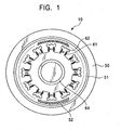
- the main configuration of a motor-driven system 10 of the first embodiment is constituted by an outer rotor type rotor 52 made of a permanent magnet having north (N) and south (S) magnetic poles formed alternately on the inner circumferential portion, a stator 62 made of a magnetic substance, and an outer rotating body 50 such as a tire, a drum or the like.
- the stator 62 has a plurality of main poles (twelve in Fig. 1 ) A1 - C2 formed radially, and windings 61 wound on the main poles A1 - C2.
- the main poles of the stator 62 are disposed in opposition to the magnetic pole portion of the rotor 52 through an air gap.
- the numerical number 64 designates a hollow fixed shaft.
- each of the main poles A1 - C2 of the stator 62 is provided with an inductor constituted by a plurality of magnetic teeth formed at the forward end of the main pole, as shown in Fig. 1 . That is, the inductors formed at the forward ends of the respective main poles A1 - C2 are made to be in opposition to the magnetic poles of the rotor 52.
- the reference numeral 51 designates a magnetic back yoke for the outer rotor type rotor 52. It is desirable to provide such a magnetic back yoke 51 to make the magnetic path sure.
- the reference numeral 64 designates a fixed shaft; 65, bearings; and 66 and 67, brackets provided on the opposite sides of the motor.
- the rotor 52 has a configuration of a permanent magnet type rotor constituted by a ring-like integral magnet as shown in Fig. 1 , the rotor 52 is not limited to such a configuration within the scope of the appended claims.
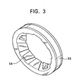
- the rotor 52 may have a configuration of a special hybrid type rotor (hereinafter referred to as a "HB-type rotor") in which two rotor magnetic poles 54 formed from claw-pole-like magnetic substances respectively are used so that a permanent magnet 53 magnetized in two poles in the axial direction is sandwiched by the two rotor magnetic poles 54.
- a HB-type rotor a special hybrid type rotor
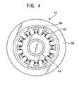
- Fig. 4 is a front view showing a comparative example of a motor-driven system
- Fig. 5 is a vertically sectioned side view of Fig. 4 .
- Figs. 4 and 5 one and the same reference number is attached to a constituent part common to each other. Further, constituent parts in Figs. 4 and 5 the same as or similar to those in Figs. 1 to 3 are referenced correspondingly. Accordingly, repeated description can be avoided.
- the motor-driven system 12 in this comparative example shows the case where the rotor 60 has teeth of a magnetic substance as shown in Fig. 4 , and the rotor 60 is made to be in opposition to the stator 62 in the same manner as that shown in Fig. 1 .
- the rotor 60 is not magnetized into multiple poles so that the resolution can be made larger than that in Fig. 1 .
- the field is not a permanent magnet field, there is a defect that the generated torque is apt to be non-linear relative to the exciting current.
- the rotor 60 has a difficulty in controllability.
- the rotational electric machine to be used in each of the motor-driven systems 10 and 12 shown in Figs. 1 to 5 is of a 3-phase type.
- connection of the 3-phase type machine is realized by star-connection or delta-connection so that 3-terminal driving can be performed to make the driving simple in comparison with any other phase structure.
- the 3-phase type rotational electric machine it is possible to obtain smooth rotation which is not affected by a third harmonic contained in the magnetic field or current. Accordingly, it can be said that the 3-phase type rotational electric machine is an actuator adapted for an electric automobile, or the like.
- Figs. 6A and 6B show the configuration of a motor-driven system 14 of the second Embodiment. Specifically, Fig. 6A is a vertically sectioned side view of the second embodiment of the motor-driven system 14, and Fig. 6B is a radially sectioned view along a line of VIB-VIB in Fig. 6A .
- Figs. 6A and 6B one and the same reference number is attached to a constituent part common to each other. Further, constituent parts used in Figs. 6A and 6B and the same as or similar to those in Figs. 1 through 5 are referenced correspondingly. Accordingly, repeated description can be avoided.
- Internal constituent parts to be used in the motor-driven system 14 of this embodiment are omitted in illustration here.
- the reduction gear 20 is mounted on a side surface and the outer rotating body 50 is mounted on the output outer circumference or the like of the reduction gear 20.
- Figs. 6A and 6B show the configuration of the planet reduction gear as the reduction gear 20.
- the planet reduction gear 20 is constituted by an internally toothed gear 23, planet gears 24 and a sun gear 25 which is connected to the rotary shaft 22.
- the reduction gear ratio may be about 1/25 relative to that of a conventional motor.
- the reduction gear 20 is of a concentric type, the reduction gear 20 can be made compact in comparison with that of a general eccentric type.
- the motor to be used in this embodiment is a low-speed and large-torque motor.
- This feature is a characteristic adapted for an electric automobile or the like.
- the motors stated in Claim 1 is of an outer rotor type which is suited to an outer rotor wheel-in-motor.
- the following two driving techniques are, of course, applicable to a motor of an inner rotor type so long as the motor has multi-poles and provided with inductors.
- a 3-phase HB type rotational electric machine in which a HB type rotor is used.
- a HB type rotor In the HB type rotor, two gear-like bodies each made of a magnetic substance with teeth the number of which is P are disposed in opposition to each other while they are displaced by 1/2 pitch from each other so that the two gear-like bodies hold an axially magnetized permanent magnet therebetween.
- Such a 3-phase HB type rotational electric machine can be made to function as an actuator which can be driven by star or delta connection, and which can obtain high resolution so as to obtain excellent cost performance.
- 2k is the number of main poles of the stator for each phase and each of k and n is an integer not smaller than 1.
- a high frequency current is generated from a battery voltage by bidirectional PWM chopping or the like and this high frequency current is stepped up by a transformer or the like and applied.
- a low-frequency current is generated by PWM chopping so that, on the contrary, the voltage of the battery is stepped down and the lowered voltage is used to perform driving.
- nearly optimum driving can be obtained.
- E designates a motional electromotive force
- the phases of the E and I are different from each other and the efficiency is not good, but at the high speed, the phases of the E and I are become identical with each other and the efficiency becomes good.
- phase-locked loop control in which the phase of the rotor and the phase of the current are made fixed is performed, the above problem can be solved.
- the driving controls correspond to Claims 4 and 5 respectively.
- a 3-phase permanent magnet type rotational electric machine with inductors provided at forward ends of the respective stator main poles.
- 2k designates the number of stator main poles for each phase.
- each of k and n is an integer not smaller than 1.
- that which is disclosed in the third embodiment is a technique which is applicable to a rotational electric machine according to any one of Claims 1 and 2; or as a comparative example to a rotational electric machine which is obtained by changing an outer rotor type rotational electric machine according to Claim 1 into an inner rotor type; or a 3-phase rotational electric machine of an outer or inner rotor type having main poles the number of which is 6k with 3-phase windings, the rotor being of a HB type in which the number of rotor teeth is P or being of a cylindrical type in which the number of rotor poles is 2P and the cylindrical rotor is magnetized into north (N) and south (S) magnetic poles alternately.
- the output can be made larger so that the motor-driven system of this embodiment has a function as an actuator which is optimum for starting up a load or for preventing step out.
- the phase of E is known and it becomes possible to control the timing for making the current I flow to result in the maximum value of EI. That is, it is possible to control the phase of current.
- Fig. 7A shows a current sequence diagram of respective phase currents ia, ib and ic of 2-phase excitation due to 120° current conduction of a 3-phase machine.
- Fig. 7B shows vector diagrams of the rotating magnetic field F respectively when these currents ia, ib and ic are made to flow in a 3-phase machine at timings t 1 , t 2 , t 3 of Fig. 7A .
- the rotating magnetic field F moves by 60° from t 1 to t 2 , and further by 60° from t 2 to t 3 .
- the rotating magnetic field F skips by 60° every time.
- T kFRsin ⁇ ⁇ ⁇
- k is a constant
- ⁇ designates a phase angle between the rotating magnetic field F and the magnetic pole position R of the rotor.
- the rotating magnetic field F cannot take any optional position but skips by 60° every time so that there may occur a situation that the phase angle ⁇ cannot take 90° according to the position of the rotor to thereby lower the torque, generate large vibration, etc.
- the phase angle ⁇ can be made near 90°.
- the current waveform becomes a 3-phase balanced sinusoidal AC current as shown in Fig. 8A .
- Fig. 8B shows the rotating magnetic field F in this case at the points of time t 1 , t 2 , ising t 7 .
- the vector of the rotating magnetic field F can continuously take any optional position, but not skip by 60° like the case described in Fig. 8B .
- the rotating magnetic field F can take optional positions continuously correspondingly to a change in the current. Accordingly, the phase angle ⁇ can be retained at 90° at all times. On the contrary, it will do to make a current flow such that the rotating magnetic field F having the phase angle ⁇ as 90° at all times is generated. Accordingly, it will do to detect the current position of the rotor R by a suitable sensor or the like so as to give such a current that gives the rotating magnetic field F with a lead angle of ⁇ degrees.
- the current is made to have a waveform of 3-phase sinusoidal wave or a microstep.
- this technique can be applied to a rotational electric machine according to any one of Claims 1 and 2; or as a comparative example to a rotational electric machine which is obtained by changing an outer rotor type rotational electric machine according to Claim 1 or 2 into an inner rotor type; or a 3-phase rotational electric machine of an outer or inner rotor type having main poles the number of which is 3m or 6k with 3-phase windings, the rotor being of a HB type in which the number of rotor teeth is P or being of a cylindrical type in which the number of rotor poles is 2P and the cylindrical rotor is magnetized into north (N) and south (S) magnetic poles alternately.
- a step angle is an electric angle of 60°.
- the motor operates as an stable actuator in which no vibration or the like is generated at the time of standstill.
- motor is made to be a closed loop brushless motor and the current is controlled so that the load angle ⁇ takes 90°, it is possible to obtain a motor-driven system having a function as an actuator which operates as a multipole brushless motor and which is stable and causes no step-out.
- an optical encoder or a resolver system in which a change of inductance is converted into a change of voltage or the like may be used.
- the motor-driven system having the stator provided with inductors according to the present invention has excellent effects as follows.
Landscapes
- Engineering & Computer Science (AREA)
- Power Engineering (AREA)
- Connection Of Motors, Electrical Generators, Mechanical Devices, And The Like (AREA)
- Permanent Magnet Type Synchronous Machine (AREA)
- Dynamo-Electric Clutches, Dynamo-Electric Brakes (AREA)
Description
- The present invention generally relates to a motor-driven system. It particularly relates to a motor-driven system for use in a motor-driven golf cart, a motor scooter, an electric automobile, and a robot carrier car; a motor-driven system for use in index table driving, drum driving in a copying machine or the like; and a motor-driven system for use in a game machine and so on.
- Conventionally, as the electric motor of an electric automobile, a permanent magnet type brushless motor, or a reluctance type brushless motor which does not use any permanent magnet has been used.
- Further, as the motor for driving a transfer drum of a copying machine or for driving a drum of a laser beam printer, an inner rotation type electric motor provided with a reduction gear has been used.
- In the configuration of such a conventional motor-driven system as described above, however, there were problems as follows.
- (1) Since the electric motor had no inductors formed out of Magnetic teeth provided at the forward ends of the respective main poles of the stator, the number of poles of the rotor was small so that the torque at a low speed was small.
- (2) In the case of performing direct driving without use of any reduction gear, it was necessary to make the number of the poles of the rotor large, and, at that time, the number of the main poles of the stator (equal to the number of slots) was large, the inner diameter of the stator was large and the motor per se was large in size.
- (3) Even in the case of using a reduction gear, if the number of the poles of the rotor was small, the reduction gear ratio was large.
- (4) In the case of closed loop driving, there was a problem that the system was expensive and the torque at a low speed was small, because the stator had no inductors and the driving was not of a 3-phase system which was simple in driving and which was large in torque.
-
US 5,386,161 discloses a structure of a three-phase permanent magnet stepping motor in which vibration and noise can be reduced and lowering of its output can be suppressed even in a high-pulse region. To this end, the motor has a three-phase, six-pole, permanent magnet stator structure, and a rotor structure having alternately arrange N and S poles the total number P of which is selected to satisfy the conditional equation of P = 12n±4 (n being a positive integer). This is applicable to both in the inner-rotor and outer-rotor structures. Further, in both the cases of the inner- and outer-rotor structures, the alternate arrangement of N and S magnetic poles of the rotor may be realized by an arrangement using a two-poles magnetized permanent magnet constituted by a combination of two claw poles, in place of the arrangement in which N and S magnetic poles are formed by directly magnetizing the outer or inner circumferential surface of a cylindrical magnet. -
US 4,658,312 discloses a disk storage device for receiving at least one storage disk provided with a central opening. The disk drive is provided with an outer rotor type driving motor having a rotor casing mounted by means of a shaft in a bearing system so as to rotate relative to a stator and receive the storage disk. The stator include magnetically active parts. At least that part of the rotor casing receiving the storage disk is made from a non-ferromagnetic material and carries the shaft either directly or by means of a hub. A shielf made from a ferromagnetic material is provided as an inner part of the rotor casing. The shield envelopes the circumference and one end of the magnetically active parts of the driving motor. The outer diameter of the rotor casing is smaller than the central opening of the storage disk. -
FR 2,598,047 -
WO91/03098 -
US 6,051,898 discloses a rotor composite type three-phase stepping motor having a stator consisting of two stator elements each having 6n pieces of stator magnetic pole with Ns pieces of pole tooth formed on the tip end of each stator magnetic pole, and a permanent magnet held by the two stator elements therebetween, a rotor of magnetic material arranged so as to face to a periphery pf the rotor, and exciting windings wound around each stator magnetic pole of the stator elements consisting of two sets of three-phase windings each wound around 3n pieces of stator magnetic pole among the 6n pieces of stator magnetic pole. A mechanical degree angle formed between the adjacent magnetic poles in the 3n pieces of magnetic pole with each set of three-phase winding is 60° m/n and a mechanical degree angle formed between the 3n pieces of magnetic pole with each set of three-phase winding is (60° m/n-θs), where Nr is a number of rotor pole teeth, each of n, m and Ns is an integer not less than 1, and θs is a step angle of (30°/Nr)k, where k is an integer number not less than 1. -
US 4,837,493 discloses a system for driving a drum which includes a pulse motor including an annular rotor fixedly mounted within the drum for rotation therewith and rotatable relative to a stator disposed within the rotor. The pitches of the rotor teeth and stator teeth are determined in such a manner that a magnetic flux linking each of the coils is changed in a sinusoidal fashion in synchronism with the rotation of the rotor. A pole position-detecting device produces a multi-phase sinusoidal pole position-detecting signal representative of the position of the magnetic poles relative to the rotor. A speed control device produces a current amplitude command signal representative of a desired torque of the rotor. A multiplier multiplies the pole-position detecting signal by the current amplitude command signal to produce a multiplication signal. A current control device is responsive to the multiplication signal to output to the coils a drive current corresponding in amplitude to the current amplitude command signal and corresponding in phase to the pole-position detecting signal, thereby energizing the coils to rotate the rotor together with the drum relative to the stator. - It is desired to solve the above problems and to provide a motor-driven system having a stator provided with inductors constituted by magnetic teeth at the forward ends of the respective main poles of the stator to thereby realize an optimal driven system for an electric automobile, a robot carrier car, a drum of a copying machine or the like.
- In order to achieve this, according to a first aspect of the present invention, there is provided a motor driven system as set forth in claim 1.
- Other aspects and embodiments of the present invention are set out in the dependent claims.
-
Fig. 1 is a front view showing a first embodiment of the motor-driven system according to the present invention; -
Fig. 2 is a vertically sectioned side view ofFig. 1 ; -
Fig. 3 is a perspective view showing the shape of another rotor, -
Fig. 4 is a front view showing a comparative example of a motor-driven system ; -
Fig. 5 is a vertically sectioned side view ofFig. 4 ; -
Fig. 6A is a vertically sectioned side view showing a second embodiment of the motor-driven system according to the present invention; -
Fig. 6B is a radially sectioned view along a line of VIB-VIB inFig. 6A ; -
Fig. 7A shows waveforms of respective phase currents as a fourth embodiment of the motor-driven system according to the present invention; -
Fig. 7B is vector diagrams showing states of the rotating magnetic field due to the respective phase currents shown inFig. 7A ; -
Fig. 8A shows waveforms of respective phase currents as a fifth embodiment of the motor-driven system according to the present invention; and -
Fig. 8B is vector diagrams showing states of the rotating magnetic field due to the respective phase currents shown inFig. 8A . - Hereunder, with reference to
Figs. 1 through 5 ,Figs. 6A and 6B ,Figs. 7A and 7B andFigs. 8A and 8B , first to sixth embodiments of the motor-driven system having a stator provided with inductors (hereinafter simply referred to as "the motor-driven system") according to the present invention will be described. - First, with reference to
Figs. 1 through 3 , the first embodiment of the motor-driven system according to the present invention will be described. Incidentally, the motor-driven system in the first embodiment corresponds to Claim 1. -
Fig. 1 is a front view of the first embodiment of the motor-driven system according to the present invention,Fig. 2 is a vertically sectioned side view ofFig. 1 , andFig. 3 is a perspective view showing the shape of another rotor which can be adapted to the first embodiment. - As shown in
Fig. 1 , the main configuration of a motor-drivensystem 10 of the first embodiment is constituted by an outerrotor type rotor 52 made of a permanent magnet having north (N) and south (S) magnetic poles formed alternately on the inner circumferential portion, astator 62 made of a magnetic substance, and an outerrotating body 50 such as a tire, a drum or the like. - The
stator 62 has a plurality of main poles (twelve inFig. 1 ) A1 - C2 formed radially, andwindings 61 wound on the main poles A1 - C2. The main poles of thestator 62 are disposed in opposition to the magnetic pole portion of therotor 52 through an air gap. Incidentally, thenumerical number 64 designates a hollow fixed shaft. - In this case, as the number of pole pairs (number of N-S pairs) of the
rotor 52 becomes large, generally, the torque increases and the motor rotates smoothly at a low speed. - However, in order to increase the number of pole pairs of the
rotor 52, it is necessary to increase the number of main poles of thestator 62 correspondingly. This results in increase in the number of coils, complex configuration of the motor and high cost. Accordingly, there is a limit in making such increase in the number of pole pairs as a matter of course. - In the motor-driven
system 10 of this embodiment, each of the main poles A1 - C2 of thestator 62 is provided with an inductor constituted by a plurality of magnetic teeth formed at the forward end of the main pole, as shown inFig. 1 . That is, the inductors formed at the forward ends of the respective main poles A1 - C2 are made to be in opposition to the magnetic poles of therotor 52. - Incidentally, in
Fig. 1 , thereference numeral 51 designates a magnetic back yoke for the outerrotor type rotor 52. It is desirable to provide such amagnetic back yoke 51 to make the magnetic path sure. - In
Fig. 2 , thereference numeral 64 designates a fixed shaft; 65, bearings; and 66 and 67, brackets provided on the opposite sides of the motor. - Although the
rotor 52 has a configuration of a permanent magnet type rotor constituted by a ring-like integral magnet as shown inFig. 1 , therotor 52 is not limited to such a configuration within the scope of the appended claims. - As a comparative example, as shown in
Fig. 3 , therotor 52 may have a configuration of a special hybrid type rotor (hereinafter referred to as a "HB-type rotor") in which two rotormagnetic poles 54 formed from claw-pole-like magnetic substances respectively are used so that apermanent magnet 53 magnetized in two poles in the axial direction is sandwiched by the two rotormagnetic poles 54. - Next, with reference to
Figs . 4 and5 , a comparative example of a motor-driven system will be described. -
Fig. 4 is a front view showing a comparative example of a motor-driven system, andFig. 5 is a vertically sectioned side view ofFig. 4 . - Incidentally, in
Figs. 4 and5 , one and the same reference number is attached to a constituent part common to each other. Further, constituent parts inFigs. 4 and5 the same as or similar to those inFigs. 1 to 3 are referenced correspondingly. Accordingly, repeated description can be avoided. - The motor-driven
system 12 in this comparative example shows the case where therotor 60 has teeth of a magnetic substance as shown inFig. 4 , and therotor 60 is made to be in opposition to thestator 62 in the same manner as that shown inFig. 1 . - In this case, the
rotor 60 is not magnetized into multiple poles so that the resolution can be made larger than that inFig. 1 . In this case, however, the field is not a permanent magnet field, there is a defect that the generated torque is apt to be non-linear relative to the exciting current. Thus, therotor 60 has a difficulty in controllability. - However, on the other hand, low cost and so on is the merit of the
rotor 60. - The rotational electric machine to be used in each of the motor-driven
systems Figs. 1 to 5 is of a 3-phase type. - The connection of the 3-phase type machine is realized by star-connection or delta-connection so that 3-terminal driving can be performed to make the driving simple in comparison with any other phase structure.
- Further, in this 3-phase type rotational electric machine, it is possible to obtain smooth rotation which is not affected by a third harmonic contained in the magnetic field or current. Accordingly, it can be said that the 3-phase type rotational electric machine is an actuator adapted for an electric automobile, or the like.
- Next, with reference to
Figs. 6A and 6B , a second embodiment of the motor-driven system according to the present invention will be described. -
Figs. 6A and 6B show the configuration of a motor-drivensystem 14 of the second Embodiment. Specifically,Fig. 6A is a vertically sectioned side view of the second embodiment of the motor-drivensystem 14, andFig. 6B is a radially sectioned view along a line of VIB-VIB inFig. 6A . - Incidentally,
Figs. 6A and 6B , one and the same reference number is attached to a constituent part common to each other. Further, constituent parts used inFigs. 6A and 6B and the same as or similar to those inFigs. 1 through 5 are referenced correspondingly. Accordingly, repeated description can be avoided. - A planet gear type reduction gear or a
harmonic reduction gear 20, which is arranged concentrically with an input siderotary shaft 22 and performs reduction gear and output, is mounted on the outer circumference or side surface of the rotor of the rotationalelectric machine 21 as an outer rotor type electric motor. Internal constituent parts to be used in the motor-drivensystem 14 of this embodiment are omitted in illustration here. - Here, in the motor-driven
system 14 shown inFig. 6A , thereduction gear 20 is mounted on a side surface and the outerrotating body 50 is mounted on the output outer circumference or the like of thereduction gear 20. - In this case, though the structure of the motor-driven
system 14 becomes complex in comparison with a single motor, large torque can be obtained in the motor-drivensystem 14 according to the present invention. - Incidentally,
Figs. 6A and 6B show the configuration of the planet reduction gear as thereduction gear 20. In this case, theplanet reduction gear 20 is constituted by an internallytoothed gear 23, planet gears 24 and asun gear 25 which is connected to therotary shaft 22. - By providing the planet reduction gear or the
harmonic reduction gear 20 which is arranged coaxially with the rotationalelectric machine 21, it is possible to form a motor-driven system compact in size and large in torque. In this case, the load inertia in the terms of the motor shaft becomes small. - Incidentally, in this case, the reduction gear ratio may be about 1/25 relative to that of a conventional motor.
- This is because the number of poles in the conventional motor which has been used in these applications is 4 (four) on the average, while the number of poles in the motor used in the motor-driven system according to the present invention is 100 on the average.
- Further, since the
reduction gear 20 is of a concentric type, thereduction gear 20 can be made compact in comparison with that of a general eccentric type. - Assume that the number of pairs of the magnetic poles of the rotor of the motor is represented by P, the density of magnetic flux in the gap is represented by B, the number of turns in the coil of windings is represented by n, the current is represented by I, the generated torque is represented by T, the electric angular velocity of the rotor is represented by ω, and the mechanical angular velocity of the rotor is represented by ωm, then the two expressions are established as follows.


- From these expressions, it can be understood that the torque T becomes large in proportion to the number of pole pairs P and that the mechanical angular velocity ωm of the rotor becomes smaller as the number of pole pairs P becomes larger.
- That is, the motor to be used in this embodiment is a low-speed and large-torque motor.
- This feature is a characteristic adapted for an electric automobile or the like.
- This is because the electric automobile requires large torque at start-up but it requires smaller torque as the speed becomes high.
- However, there may be a case where a motor requires large torque even at a high speed. Two driving techniques of the motor-driven system according to the present invention suited to such a case will be described as follows.
- Incidentally, the motors stated in Claim 1 is of an outer rotor type which is suited to an outer rotor wheel-in-motor. However, the following two driving techniques are, of course, applicable to a motor of an inner rotor type so long as the motor has multi-poles and provided with inductors.
- Of the various configurations of motors, there is a 3-phase HB type rotational electric machine in which a HB type rotor is used. In the HB type rotor, two gear-like bodies each made of a magnetic substance with teeth the number of which is P are disposed in opposition to each other while they are displaced by 1/2 pitch from each other so that the two gear-like bodies hold an axially magnetized permanent magnet therebetween. Such a 3-phase HB type rotational electric machine can be made to function as an actuator which can be driven by star or delta connection, and which can obtain high resolution so as to obtain excellent cost performance.
- In this case, if the number of teeth of the rotor is represented by P, a 3-phase HB type rotational electric machine is established under the condition that P=k(6n±1).
- Provided that, in the case of the above expression, 2k is the number of main poles of the stator for each phase and each of k and n is an integer not smaller than 1.
- For example, in a case of a 12-slot stator with m=4, a step angle is 0.6° in a stepping motor with n=8 and P=100. Further, in a case of a 6-slot stator with m=2, a step angle is 1.2° in a stepping motor with n=8 and P=50.
- In this case, the current I in the expression (1) is as follows.

- When the value of ωm is large, in order to make the current I large, it is necessary to make the applied voltage V large. Incidentally, L designates inductance.
- To this end, a high frequency current is generated from a battery voltage by bidirectional PWM chopping or the like and this high frequency current is stepped up by a transformer or the like and applied. At a low speed operation, a low-frequency current is generated by PWM chopping so that, on the contrary, the voltage of the battery is stepped down and the lowered voltage is used to perform driving. Thus, nearly optimum driving can be obtained.
- Further, the following expression (4) is established.

- Here, E designates a motional electromotive force.
- At this time, paricularly when driving is performed with open loop, the phases of the E and I become important.
- Generally, at the low or intermediate speed, the phases of the E and I are different from each other and the efficiency is not good, but at the high speed, the phases of the E and I are become identical with each other and the efficiency becomes good.
- Accordingly, for example, if a phase-locked loop control (PLL control) in which the phase of the rotor and the phase of the current are made fixed is performed, the above problem can be solved. The driving controls correspond to
Claims 4 and 5 respectively. - There is provided a 3-phase permanent magnet type rotational electric machine with inductors provided at forward ends of the respective stator main poles. The rotational electric machine is particularly useful when the number of the stator main poles for each phase is selected to be 3 (in the case where m=1) and 6 (in the case where m=2). In this case, if P=k(6n±1) is established, a 3-phase rotational electric machine can be configured to be large in the output torque in comparison with a 2-phase or 5-phase machine. Here, 2k designates the number of stator main poles for each phase. Further, each of k and n is an integer not smaller than 1.
- That is, in this meaning, that which is disclosed in the third embodiment is a technique which is applicable to a rotational electric machine according to any one of
Claims 1 and 2; or as a comparative example to a rotational electric machine which is obtained by changing an outer rotor type rotational electric machine according to Claim 1 into an inner rotor type; or a 3-phase rotational electric machine of an outer or inner rotor type having main poles the number of which is 6k with 3-phase windings, the rotor being of a HB type in which the number of rotor teeth is P or being of a cylindrical type in which the number of rotor poles is 2P and the cylindrical rotor is magnetized into north (N) and south (S) magnetic poles alternately. - From this point of view, if the motor of this embodiment is subjected to closed loop control, the output can be made larger so that the motor-driven system of this embodiment has a function as an actuator which is optimum for starting up a load or for preventing step out.
- Thus, that which is disclosed in this third embodiment shows specific means which is necessary for realizing that which is stated in claim 1 above. That is, by knowing the current position of the rotor, current is made to flow in the coil of the windings so that a certain angle from the rotor is made to be fixed.
- That is, the motional electromotive force E is shown as E=dØ/dt with respect to the rotor magnetic flux Ø. Accordingly, the phase is delayed by 90°
- Thus, if the positional information of the rotor is detected, the phase of E is known and it becomes possible to control the timing for making the current I flow to result in the maximum value of EI. That is, it is possible to control the phase of current.
- Next, the fourth and fifth embodiments of the present invention will be described with reference to
Figs. 7A and 7B andFigs. 8A and 8B , respectively. - If a 3-phase stepping motor which is excellent in efficiency and which shows torque larger than that in a 2-phase or 5-phase machine is subjected to lead angle control, it is possible to obtain a motor-driven system having a function as an actuator which is excellent in torque property and small in vibration and noise, compared with that of the 2-phase machine or the like.
-
Fig. 7A shows a current sequence diagram of respective phase currents ia, ib and ic of 2-phase excitation due to 120° current conduction of a 3-phase machine. -
Fig. 7B shows vector diagrams of the rotating magnetic field F respectively when these currents ia, ib and ic are made to flow in a 3-phase machine at timings t1, t2, t3 ofFig. 7A . - That is, the rotating magnetic field F moves by 60° from t1 to t2, and further by 60° from t2 to t3. Thus, the rotating magnetic field F skips by 60° every time.
- R designates the magnetic pole position of the rotor and it is possible to show the torque T as follows.

- Here, k is a constant, γ designates a phase angle between the rotating magnetic field F and the magnetic pole position R of the rotor.
- Accordingly, the torque T can be made maximum at γ =90°. However, in a case of rectangular current of 120° current conduction as shown in
Fig. 7A , as described above, the rotating magnetic field F cannot take any optional position but skips by 60° every time so that there may occur a situation that the phase angle γ cannot take 90° according to the position of the rotor to thereby lower the torque, generate large vibration, etc. - On the contrary, if microstep in which the current is highly divided into many parts is employed, the phase angle γ can be made near 90°. As an extreme case of the highly divided microstep, the current waveform becomes a 3-phase balanced sinusoidal AC current as shown in
Fig. 8A . -
Fig. 8B shows the rotating magnetic field F in this case at the points of time t1, t2, ...... t7. In this case, the vector of the rotating magnetic field F can continuously take any optional position, but not skip by 60° like the case described inFig. 8B . - That is, as shown in
Fig. 8A , in optional points of time t1 and t2, the rotating magnetic field F can take optional positions continuously correspondingly to a change in the current. Accordingly, the phase angle γ can be retained at 90° at all times. On the contrary, it will do to make a current flow such that the rotating magnetic field F having the phase angle γ as 90° at all times is generated. Accordingly, it will do to detect the current position of the rotor R by a suitable sensor or the like so as to give such a current that gives the rotating magnetic field F with a lead angle of γ degrees. - Accordingly, preferably, the current is made to have a waveform of 3-phase sinusoidal wave or a microstep.
- Incidentally, with respect to the number of main poles in the fifth embodiment, similarly to the case of the fourth embodiment, this technique can be applied to a rotational electric machine according to any one of
Claims 1 and 2; or as a comparative example to a rotational electric machine which is obtained by changing an outer rotor type rotational electric machine according toClaim 1 or 2 into an inner rotor type; or a 3-phase rotational electric machine of an outer or inner rotor type having main poles the number of which is 3m or 6k with 3-phase windings, the rotor being of a HB type in which the number of rotor teeth is P or being of a cylindrical type in which the number of rotor poles is 2P and the cylindrical rotor is magnetized into north (N) and south (S) magnetic poles alternately. - Next, the sixth embodiment of the present invention will be described.
- In a 3-phase permanent magnet type stepping motor, as described with reference to
Fig. 7B , a step angle is an electric angle of 60°. - Further, in the range where the load angle γ is not larger than 90°, torque which is always attracted to the axis of the rotating magnetic field F acts normally and it is preferable in economical point to make the motor be an open loop stepping motor. The motor operates as an stable actuator in which no vibration or the like is generated at the time of standstill.
- However, if the load increases so that the load angle γ exceeds 90°, the motor becomes apt to generate synchronous step out.
- In this case, if motor is made to be a closed loop brushless motor and the current is controlled so that the load angle γ takes 90°, it is possible to obtain a motor-driven system having a function as an actuator which operates as a multipole brushless motor and which is stable and causes no step-out.
- The present invention is not limited to those embodiments described above but can be modified variously within the scope of the above-mentioned technical thought of the present invention.
- Incidentally, as the positional information sensor for detecting the rotor of a 3-phase motor with inductors according to the present invention, an optical encoder or a resolver system in which a change of inductance is converted into a change of voltage or the like may be used.
- By making the configuration as any one of those embodiments described above, the motor-driven system having the stator provided with inductors according to the present invention has excellent effects as follows.
- (1) The configuration stated in Claim 1 shows the following effects.
- (i) With the configuration that each main pole of the stator is provided with an inductor constituted by a plurality of magnetic teeth, the number of poles of the rotor can be made large so that low-speed and large-torque driving can be performed.
- (ii) Because of the outer rotor type configuration, the rotor outside portion or the like can be fitted to an inside or a side portion of a wheel or a drum, so that the system can be made compact.
- (iii) The magnetic poles of the outer rotor type permanent magnet rotor can be formed by magnetization so that the magnetic field flux can be distributed sinusoidally to thereby bring about low vibration.
- (2) Besides the above-mentioned effects (1) (i)-(ii), in a configuration where the rotor has magnetic teeth formed on the inner circumference thereof as described above under the heading comparative example, it is possible to make the configuration simple and inexpensive.
- (3) If a reduction gear is provided as stated above, it is possible to make the reduction gear small in reduction gear ratio and compact in size.
- (4) If the stator has a 3-phase winding structure as stated above, the motor is made to be a 3-phase machine so that 3-terminal driving can be performed with star-connection or delta connection and the driving becomes simple.
Further, in the case of 3-phase machine, the machine is not affected by the magnetic field or the third harmonic of the current so that the rotation of the motor is smooth. - (5) The applied voltage can be stepped up/down by chopping. Accordingly, if constant current driving is performed, the motor can be made to start up at high-speed large torque driving and the voltage applied to the motor can be changed in accordance with the speed. As a result, it is possible to perform high output and high efficient driving.
- (6) If the phase of current is controlled with respect to the motional electromotive force of the rotational electric machine as stated above, it is possible to perform driving with the optimum torque in accordance with the speed.
- (7) If the configuration is made as stated in claim 1, by realizing this configuration in a 3-phase machine, it is possible to provide an actuator which is excellent in efficiency with low vibration, compared with a conventional case (2-phase machine).
- (8) If the configuration is made as stated in
embodiments 4 and 5 above, the excitation current waveform of the 3-phase machine can be made to be not only rectangular waveform with 120°current conduction but also stepwise waveform of microsteps or sinusoidal waveform. Accordingly, the degree of freedom in the value of lead angle γ increases, it is possible to realize γ = 90°, and it is possible to further improve the efficiency. - (9) If the configuration is made as stated in the sixth embodiment, in accordance with the value of the angle γ, it is possible to make the machine operate as a 3-phase stepping motor or as a 3-phase brushless motor. Accordingly, in accordance with the load, it is possible to cope with the load by an optimum kind of motor by making the motor operate as a 3-phase stepping motor or a 3-phase brushless motor. Thus, convenience in use, improvement in general characteristic of a motor suited for the load, and improvement in economical point can be obtained.
Claims (6)
- A motor driven system (10) comprising:a rotational electric machine comprising:a stator (62) having an annular magnetic substance, main poles (A1-C2) provided so as to extend radially outward from said magnetic substance, windings (61) wound on said main poles (A1-C2) respectively, and inductors each constituted by a plurality of magnetic teeth formed at a forward end of corresponding one of said main poles (A1-C2); andan outer rotor cylindrical type permanent magnet rotor (52) having north (N) and south (S) magnetic poles arranged alternately on an inner circumference of said rotor (52) and in a rotating direction of said rotor, said stator (62) and said rotor (52) being in opposition to each other while an air gap is held therebetween; characterized in thatsaid stator (62) has main poles (A1-C2) the number of which is 6k with 3-phase windings, the number of rotor poles is 2P, and P=k(6n±1), in which 2k is the number of main poles of the stator for each phase and each of k and n is an integer not smaller than 1; further characterized in thatan outer rotating body (50) such as a tire, a drum, a table or the like is mounted on an outer circumferential portion or on a side portion of said rotor (52) ; and in thatpositional information of said rotor (52) is obtained to thereby obtain timing of excitation of windings (61).
- The motor driven system (10, 12) according to Claim 1, wherein a voltage of a battery to be applied to said rotational electric machine is stepped up/down by chopping.
- The motor driven system (10, 12) according to Claim 1, wherein a phase of current relative to amotional electromotive force of said rotational electric machine is controlled.
- The motor driven system (10, 12) according to Claim 1 wherein an axis of rotatingmagnetic field is excited by 3 phase AC current excitation, microstep excitation, or full step excitation, which is advanced by γ degrees with respect to a shaft of said rotor at a present position.
- The motor driven system according to Claim 4, wherein the value of γ is equal to 90° (γ = 90°) in terms of electrical angle.
- The motor driven system according to Claim 4, wherein when the value of γ is in a range of 0° < γ ≦ 90°, said motor is driven as an open loop stepping motor, or wherein when γ > 90°, said motor is driven as a closed loop brushless motor.
Applications Claiming Priority (4)
| Application Number | Priority Date | Filing Date | Title |
|---|---|---|---|
| JP2000229794 | 2000-07-28 | ||
| JP2000229794 | 2000-07-28 | ||
| JP2001202713 | 2001-07-03 | ||
| JP2001202713 | 2001-07-03 |
Publications (3)
| Publication Number | Publication Date |
|---|---|
| EP1187302A2 EP1187302A2 (en) | 2002-03-13 |
| EP1187302A3 EP1187302A3 (en) | 2005-05-04 |
| EP1187302B1 true EP1187302B1 (en) | 2008-07-23 |
Family
ID=26596967
Family Applications (1)
| Application Number | Title | Priority Date | Filing Date |
|---|---|---|---|
| EP01306437A Expired - Lifetime EP1187302B1 (en) | 2000-07-28 | 2001-07-26 | Motor-driven system with toothed stator poles |
Country Status (3)
| Country | Link |
|---|---|
| US (1) | US6731033B2 (en) |
| EP (1) | EP1187302B1 (en) |
| DE (1) | DE60134928D1 (en) |
Cited By (1)
| Publication number | Priority date | Publication date | Assignee | Title |
|---|---|---|---|---|
| EP2434635A1 (en) | 2010-09-28 | 2012-03-28 | Fresenius Kabi Deutschland GmbH | Drive device for a medical pump with a step motor |
Families Citing this family (17)
| Publication number | Priority date | Publication date | Assignee | Title |
|---|---|---|---|---|
| FR2821024B1 (en) * | 2001-02-20 | 2003-06-13 | Leroy Somer Moteurs | DRIVE ELEMENT SUCH AS A DRIVE WHEEL OR A LIFTING WINCH COMPRISING A SYNCHRONOUS MOTOR |
| JP3560947B2 (en) * | 2001-11-06 | 2004-09-02 | 株式会社日立製作所 | Rotating electric machine |
| EP1432104B1 (en) * | 2002-12-16 | 2006-12-06 | ebm-papst St. Georgen GmbH & Co. KG | Outer rotor motor with fixed spindle |
| US20060091755A1 (en) * | 2004-10-28 | 2006-05-04 | Precise Automation, Llc | Transverse flux switched reluctance motor and control methods |
| US7332881B2 (en) | 2004-10-28 | 2008-02-19 | Textron Inc. | AC drive system for electrically operated vehicle |
| JP2007185021A (en) * | 2006-01-05 | 2007-07-19 | Japan Servo Co Ltd | Rotating electric machine with speed change mechanism and drive device using the same |
| US20080164106A1 (en) * | 2007-01-04 | 2008-07-10 | Textron Inc. | Electric Brake for Utility Vehicles |
| US7926889B2 (en) * | 2007-10-29 | 2011-04-19 | Textron Innovations Inc. | Hill hold for an electric vehicle |
| WO2009064440A2 (en) | 2007-11-13 | 2009-05-22 | Emerson Climate Technologies, Inc. | Three-phase detection module |
| US9312740B2 (en) * | 2008-10-12 | 2016-04-12 | Christopher C. Sappenfield | Apparatus comprising counter-rotational mechanisms and related methods to convey current |
| US7902708B2 (en) * | 2009-01-07 | 2011-03-08 | Shimon Elmaleh | Electro-magnetic motor generator system |
| CN101964556B (en) * | 2010-09-13 | 2013-05-01 | 精进电动科技(北京)有限公司 | Rotor device of starting and power-generating integrated motor and rotor working system |
| CN103825497B (en) * | 2014-02-25 | 2016-01-27 | 周阳阳 | Pulse electromagnetic engine |
| KR101652703B1 (en) * | 2015-02-02 | 2016-09-01 | 주식회사 세진아이지비 | A transmission device for converting a torque |
| DE102017207116A1 (en) * | 2017-04-27 | 2018-10-31 | Zf Friedrichshafen Ag | Anti-roll stabilizer and use of a roll stabilizer in a motor vehicle |
| DE102020115228B4 (en) * | 2020-06-09 | 2025-10-30 | Schaeffler Technologies AG & Co. KG | Drive device for a robot and robots with at least one such drive device |
| US12027916B2 (en) * | 2020-07-30 | 2024-07-02 | IAM Robotics, LLC | Direct drive outer rotor brushless DC motor drive wheel |
Family Cites Families (20)
| Publication number | Priority date | Publication date | Assignee | Title |
|---|---|---|---|---|
| US3933217A (en) * | 1973-04-04 | 1976-01-20 | Carl Hurth, Maschinen- Und Zahnradfabrik | Drive gear system for motor vehicles |
| US4274023A (en) * | 1979-05-10 | 1981-06-16 | Lamprey Donald F | Compact variable speed drive for electric motor |
| JPS6052660B2 (en) * | 1979-06-04 | 1985-11-20 | 松下電器産業株式会社 | Rotational speed signal detector |
| US4658312A (en) * | 1981-09-07 | 1987-04-14 | Papst-Motoren Gmbh & Co. K.G. | Disk storage drive |
| US4628891A (en) * | 1984-02-15 | 1986-12-16 | Nippondenso Co., Ltd. | Magneto-generator for internal combustion engine |
| US4837493A (en) * | 1985-12-18 | 1989-06-06 | Shinko Electric Co., Ltd. | System for driving drum |
| FR2598047A1 (en) * | 1986-04-23 | 1987-10-30 | Etri Sa | Electric motor with a one-piece rotor and method for manufacturing such a motor |
| US4843292A (en) * | 1987-03-02 | 1989-06-27 | Yokogawa Electric Corporation | Direct drive motor system |
| US4763034A (en) * | 1987-07-10 | 1988-08-09 | Sigma Instruments, Inc. | Magnetically enhanced stepping motor |
| WO1991003098A1 (en) * | 1989-08-17 | 1991-03-07 | Universidad De Oviedo | Motor-wheel with variable reluctance step-by-step motor for low speed drive |
| US5334894A (en) * | 1991-05-14 | 1994-08-02 | Shinko Electric Co., Ltd. | Rotary pulse motor |
| JP3140814B2 (en) * | 1991-10-18 | 2001-03-05 | 日本サーボ株式会社 | Permanent magnet type stepping motor |
| FR2682920B1 (en) * | 1991-10-23 | 1993-12-03 | Auxilec | ELECTRIC DRIVE CHAIN INTEGRATING THE BRAKE MOTOR / GENERATOR FUNCTION WITH THE CHARGER AND / OR CONVERTER FUNCTION. |
| JP3071064B2 (en) * | 1992-04-20 | 2000-07-31 | 日本サーボ株式会社 | Permanent magnet type stepping motor |
| JP2740893B2 (en) * | 1993-11-01 | 1998-04-15 | 日本サーボ株式会社 | Permanent magnet type stepping motor |
| DE4421428C1 (en) * | 1994-06-18 | 1995-07-27 | Fichtel & Sachs Ag | Planetary gearing esp. for electric drive of road vehicle wheel |
| US5744895A (en) * | 1995-01-31 | 1998-04-28 | Nippondenso Co., Ltd. | System for driving electric vehicles |
| JP3376373B2 (en) * | 1995-06-07 | 2003-02-10 | ミネベア株式会社 | Motor structure |
| US5919109A (en) * | 1996-10-16 | 1999-07-06 | Linde Aktiengesellschaft | Drive axle with planetary gear |
| US6051898A (en) * | 1998-01-02 | 2000-04-18 | Japan Servo Co., Ltd. | Stepping motor having external rotor and electromagnetic-combined-permanent-magnet stator |
-
2001
- 2001-07-26 EP EP01306437A patent/EP1187302B1/en not_active Expired - Lifetime
- 2001-07-26 DE DE60134928T patent/DE60134928D1/en not_active Expired - Lifetime
- 2001-07-27 US US09/915,335 patent/US6731033B2/en not_active Expired - Fee Related
Non-Patent Citations (1)
| Title |
|---|
| MOHAN; UNDELAND; ROBBINS: "POWER ELECTRONICS, Converters, Application, and Design", 1995, JOHN WILEY & SONS, NEW YORK, UNITED STATES OF AMERICA * |
Cited By (2)
| Publication number | Priority date | Publication date | Assignee | Title |
|---|---|---|---|---|
| EP2434635A1 (en) | 2010-09-28 | 2012-03-28 | Fresenius Kabi Deutschland GmbH | Drive device for a medical pump with a step motor |
| WO2012048976A1 (en) | 2010-09-28 | 2012-04-19 | Fresenius Kabi Deutschland Gmbh | Drive device for a medical pump having a stepper motor |
Also Published As
| Publication number | Publication date |
|---|---|
| EP1187302A3 (en) | 2005-05-04 |
| EP1187302A2 (en) | 2002-03-13 |
| US6731033B2 (en) | 2004-05-04 |
| US20020024267A1 (en) | 2002-02-28 |
| DE60134928D1 (en) | 2008-09-04 |
Similar Documents
| Publication | Publication Date | Title |
|---|---|---|
| EP1187302B1 (en) | Motor-driven system with toothed stator poles | |
| US6995494B2 (en) | Axial gap brushless DC motor | |
| JP3169276B2 (en) | Hybrid type stepping motor | |
| JP2549863B2 (en) | Electromagnetic device | |
| EP1414140A1 (en) | Electric machine, in particular an axial gap brushless DC motor | |
| JPH0614514A (en) | Permanent magnet type stepping motor | |
| WO2020150536A1 (en) | A system and method for controlling a multi-tunnel electric machine | |
| JPH06284665A (en) | Driver for electric automobile | |
| JP4306851B2 (en) | Lead angle correction method for magnet type brushless motor | |
| TW201737602A (en) | Disk-type electric motor, electrically driven vehicle and method for controlling the same | |
| JPH10155262A (en) | Magnet type brushless motor | |
| EP1324472B1 (en) | Inner and outer rotor slotless electric motor with ring-type winding | |
| JP2000139047A (en) | Permanent magnet type motor | |
| JP3117164B2 (en) | Permanent magnet rotating electric machine, control method and control device thereof, and electric vehicle using the same | |
| US7633191B2 (en) | Multiphase step motor | |
| EP0348984A1 (en) | Binary brushless alternator and motor | |
| JP2010516224A (en) | Multi-phase drive or generator machine | |
| JP2003348809A (en) | Inner rotor type motor with magnet | |
| JP2754141B2 (en) | Permanent magnet type three-phase stepping motor | |
| JP3124499B2 (en) | Composite three-phase stepping motor and method of driving the same | |
| US12573926B2 (en) | Bipolar induction electric machine | |
| JPH09168265A (en) | Synchronous / induction combined electric machine and synchronous electric machine | |
| JP2003088083A (en) | Motor drive system having inductor in stator | |
| JP2011182495A (en) | Motor | |
| JP3816607B2 (en) | Stepping motor |
Legal Events
| Date | Code | Title | Description |
|---|---|---|---|
| PUAI | Public reference made under article 153(3) epc to a published international application that has entered the european phase |
Free format text: ORIGINAL CODE: 0009012 |
|
| AK | Designated contracting states |
Kind code of ref document: A2 Designated state(s): AT BE CH CY DE DK ES FI FR GB GR IE IT LI LU MC NL PT SE TR |
|
| AX | Request for extension of the european patent |
Free format text: AL;LT;LV;MK;RO;SI |
|
| PUAL | Search report despatched |
Free format text: ORIGINAL CODE: 0009013 |
|
| AK | Designated contracting states |
Kind code of ref document: A3 Designated state(s): AT BE CH CY DE DK ES FI FR GB GR IE IT LI LU MC NL PT SE TR |
|
| AX | Request for extension of the european patent |
Extension state: AL LT LV MK RO SI |
|
| 17P | Request for examination filed |
Effective date: 20050530 |
|
| 17Q | First examination report despatched |
Effective date: 20050629 |
|
| AKX | Designation fees paid |
Designated state(s): DE |
|
| GRAP | Despatch of communication of intention to grant a patent |
Free format text: ORIGINAL CODE: EPIDOSNIGR1 |
|
| GRAS | Grant fee paid |
Free format text: ORIGINAL CODE: EPIDOSNIGR3 |
|
| GRAA | (expected) grant |
Free format text: ORIGINAL CODE: 0009210 |
|
| AK | Designated contracting states |
Kind code of ref document: B1 Designated state(s): DE |
|
| REF | Corresponds to: |
Ref document number: 60134928 Country of ref document: DE Date of ref document: 20080904 Kind code of ref document: P |
|
| PLBE | No opposition filed within time limit |
Free format text: ORIGINAL CODE: 0009261 |
|
| STAA | Information on the status of an ep patent application or granted ep patent |
Free format text: STATUS: NO OPPOSITION FILED WITHIN TIME LIMIT |
|
| 26N | No opposition filed |
Effective date: 20090424 |
|
| PGFP | Annual fee paid to national office [announced via postgrant information from national office to epo] |
Ref country code: DE Payment date: 20120718 Year of fee payment: 12 |
|
| PG25 | Lapsed in a contracting state [announced via postgrant information from national office to epo] |
Ref country code: DE Free format text: LAPSE BECAUSE OF NON-PAYMENT OF DUE FEES Effective date: 20140201 |
|
| REG | Reference to a national code |
Ref country code: DE Ref legal event code: R119 Ref document number: 60134928 Country of ref document: DE Effective date: 20140201 |