EP1187270A2 - Electric connection box - Google Patents
Electric connection box Download PDFInfo
- Publication number
- EP1187270A2 EP1187270A2 EP01307603A EP01307603A EP1187270A2 EP 1187270 A2 EP1187270 A2 EP 1187270A2 EP 01307603 A EP01307603 A EP 01307603A EP 01307603 A EP01307603 A EP 01307603A EP 1187270 A2 EP1187270 A2 EP 1187270A2
- Authority
- EP
- European Patent Office
- Prior art keywords
- connection box
- cover
- box body
- wire
- side wall
- Prior art date
- Legal status (The legal status is an assumption and is not a legal conclusion. Google has not performed a legal analysis and makes no representation as to the accuracy of the status listed.)
- Granted
Links
Images



Classifications
-
- H—ELECTRICITY
- H01—ELECTRIC ELEMENTS
- H01R—ELECTRICALLY-CONDUCTIVE CONNECTIONS; STRUCTURAL ASSOCIATIONS OF A PLURALITY OF MUTUALLY-INSULATED ELECTRICAL CONNECTING ELEMENTS; COUPLING DEVICES; CURRENT COLLECTORS
- H01R13/00—Details of coupling devices of the kinds covered by groups H01R12/70 or H01R24/00 - H01R33/00
- H01R13/46—Bases; Cases
- H01R13/52—Dustproof, splashproof, drip-proof, waterproof, or flameproof cases
- H01R13/5213—Covers
Definitions
- This invention relates to an improved electric connection box provided with a waterproof cover which covers a wire connection portion, provided at a bottom surface of a connection box body, and forms a wire receiving space for leading wires, connected to the wire connection portion, out from a wire lead-out portion.
- a wire harness is connected to circuit parts (such as a fuse and a relay) and other electronic parts
- circuit parts such as a fuse and a relay
- various such electric connection boxes of the type comprising a connection box body, which has at its lower surface a wire connection portion to which a wire harness is connected, and also has at its upper surface a parts-mounting portion for mounting circuit parts and electronic parts thereon, and a waterproof cover for covering the wire connection portion and the parts-mounting portion.
- the waterproof cover of such a conventional electric connection box is divided into an upper cover, covering the upper surface of the connection box body, and a lower cover covering the lower surface of the connection box body.
- the two members to be connected together are mated with each other in an upward-downward direction, and then are locked together by lock means such as lock arms.
- connection box body When the maintenance and inspecting operation for fuses and relays in the connection box body, as well as the inspecting operation for the wire connection portion, are to be effected, usually, the upper cover is first removed, and then the connection box body, received in the lower cover, is removed upwardly therefrom.
- connection box body at which the circuit parts and the wire connection portion are provided, have relatively large dimensions. Therefore, it is necessary that the empty space, required for attaching and detaching the connection box body, should be large, and thus the large empty space must be provided above the electric connection box. Therefore, in some cases, it was difficult to achieve a high-density arrangement of the parts within the engine room, and besides the degree of freedom of the arrangement within the engine room was lowered, which made it difficult to achieve a proper arrangement design.
- an electric connection box comprising a waterproof cover which covers a wire connection portion, provided at a bottom surface of a connection box body, and forms a wire receiving space for leading wires, connected to the wire connection portion, out from a wire lead-out portion;
- the waterproof cover comprises a cover body, slidably engaged with the connection box body along the bottom surface of the connection box body, and a cover side wall portion which is provided downwardly at one side edge of the connection box body so as to close a notch opening formed in one side surface of the cover body.
- connection box body can be attached to and detached from the cover body of the waterproof cover by sliding this connection box body along the. bottom surface thereof, and an empty space, which must be reserved around the electric connection box so as to attach and detach the connection box body at the time of the maintenance and inspection, need only to have an occupancy area which corresponds in size to the cover side wall portion, and allows the sliding movement of the connection box body, and this occupancy area is much smaller as compared with the bottom surface of the connection box body which must provide a large occupancy area because of the provision of the wire connection portion and so on.
- the empty space which need to be reserved around the electric connection box so as to attach and detach the connection box body relative to the waterproof cover at the time of the maintenance and inspection, can be saved as compared with the conventional electric connection box in which the connection box body is removed in the upward-downward direction, perpendicular to the bottom surface thereof, at the time of the maintenance and inspection. Therefore, the degree of freedom of an arrangement design of the electric connection box and other parts within an engine room can be enhanced, and a high-density arrangement of the parts can be achieved.
- a wire capture-prevention wall for guiding and holding the wires at the inside of the cover is formed on and projects from that portion of an inner surface of the cover side wall portion disposed near to a peripheral edge thereof including at least the peripheral edge of a distal end portion of the cover side wall portion.
- connection box body received in the. wire receiving space
- wire capture-prevention wall formed on the cover side wall portion, guides the extra portion of the wires to the inside of the cover, and holds it there.
- the wire capture-prevention wall functions also as a reinforcing rib which increases the strength of the cover side wall portion, and therefore the deformation of the cover side wall portion due to a molding strain can be reduced, and the stable molding dimensional accuracy can be secured, and therefore the ability of this cover side wall portion to close the notch opening can be enhanced.
- the wire capture-prevention wall is fitted in the notch opening of the cover body in overlapping relation to a wall surface of the cover body forming a peripheral edge portion of the notch opening.
- the wire capture-prevention wall fitted in the notch opening in the cover body, functions as a reinforcing member for suppressing the deformation of the edge portion of the notch opening, thereby increasing the strength of the cover body. Therefore, even when the wall of the cover body is reduced in thickness and weight, the cover body can have the sufficient strength.
- the cover side wall portion is formed integrally with a slide member which is slidably engaged with the cover body and allows the connection box body to be attached thereto and detached therefrom.
- connection box body provided with the wire connection portion, is designed to be displaced relative to the slide member in the upward-downward direction so as to be brought into and out of engagement therewith.
- this connection box body can be moved not only in the sliding direction along the bottom surface thereof, but also in the upward-downward direction perpendicular to this bottom surface, and in accordance with the kind of the vehicle, the desired attaching and detaching direction can be selected at the time of the maintenance and inspection, and the degree of freedom of the arrangement design of the electric connection box in the engine room or other portion is further enhanced.
- Fig. 1 is an exploded, perspective view of one preferred embodiment of the electric connection box of the invention
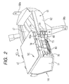
- Fig. 2 is a perspective view (as seen from the right side) showing a condition in which a connection box body of Fig. 1 is drawn from a cover body
- Fig. 3 is a perspective view (as seen from the left side) showing a condition in which the connection box body of Fig. 1 is in the process of sliding insertion into the cover body
- Fig. 4 is a vertical cross-sectional view showing a condition in which the sliding insertion of the connection box body of Fig. 1 into the cover body is started
- Fig. 5 is a vertical cross-sectional view showing a condition in which the sliding insertion of the connection box body of Fig. 1 into the cover body is finished
- Fig. 6 is a perspective view of the connection box body of Fig. 1 as seen from the bottom thereof.
- the electric connection box 41 of this embodiment comprises the connection box body (such as a junction box and a fuse box) 50, and a waterproof cover 45 for covering a bottom surface of the connection box body 50.
- connection box body 50 has parts-mounting portions 52 and wire connection portions 54 provided at the bottom surface thereof (shown in Fig. 6), and circuits parts such as fuses and relays are attached in a fitted manner to the parts-mounting portions 52, and wires (cable) 80 such as a wire harness are connected to the wire connection portions 54 through connectors.
- the waterproof cover 45 comprises the cover body 60 and a cover side wall portion 71.
- This cover 45 covers the bottom surface of the connection box body 50 and forms together with the bottom surface of the connection box body 50 a wire receiving space 47 therebetween, and this wire receiving space 47 enables the wires 80 of the wire harness connected to the wire connection portions 54 through the connectors to be led out from a wire lead-out portion 62 provided in a predetermined direction.
- the cover body 60 is molded into an integral construction, using a heat-resistant insulative resin material and this cover body includes the wire lead-out portion 62, sliding engagement portions 64 slidably engageable with the connection box body 50 along the bottom surface thereof, a notch opening 66, which is formed in one side wall of the cover body, and is open in the sliding direction by the sliding engagement portions 64, and brackets 68a and 68b for being fixed to a vehicle body.
- the cover side wall portion 71 is provided downwardly at one side edge of the connection box body 50.
- Slide rail portions 73 provided at the connection box body 50 are fitted in the sliding engagement portions 64 of the cover body 60, and then the connection box body 50 is slid to be received in the cover body 60, and at this time the cover side wall portion 71 closes the notch opening 66.
- connection box body 50 When the connection box body 50 is slid to be received in the cover body 60, so that the cover side wall portion 71 closes the notch opening 66, retaining projections 79 formed respectively at opposite side edges of the cover side wall portion 71 are retained respectively by lock arms 69 formed respectively at corresponding portions of the outer surface of the cover body 60, so that the connection box body 50 is fixedly connected to the cover body 60.
- the cover side wall portion 71 is formed integrally with a slide member 70, which is generally formed in a rectangular frame member by molding to which the connection box body 50 is releasably attached and is slidably engaged with the cover body 60.
- connection box body 50 When the connection box body 50 is fitted into a frame portion 77 of the slide member 70 from the upper side, engagement projections 56 formed on the outer peripheral surface of the connection box body 50 are engaged respectively with elastic retaining piece portions 78 formed on the frame portion 77, so that the connection box body 50 is fixedly connected to the slide member 70.
- a wire capture-prevention wall 75 for guiding and holding the wires 80 within the cover 45 is formed on an inner surface of the cover side wall portion 71 of the slide member 70 near to a peripheral edge thereof including at least the peripheral edge of the distal end portion thereof, and this prevention wall 75 projects from this inner surface in the sliding direction (direction of arrow (C) in the drawings).
- the wire capture-prevention wall 75 serves to hold an extra portion 80a of the wires 80 to prevent it from being extended beyond the range of the wire receiving space 47 of the cover body 60 as shown in Fig. 4.
- the wire capture-prevention wall 75 is fitted in the notch opening 66 of the cover body 60 in overlapping relation to a wall surface 66a of the cover body 60 forming a peripheral edge portion of the notch opening 66, as shown in Fig. 5.
- connection box body 50 can be attached to and detached from the cover body 60 of the waterproof cover 45 by sliding this connection box body 50 along the bottom surface thereof as indicated by arrow (C) in Figs. 4 and 5. Therefore, an empty space, which must be reserved around the electric connection box 41 so as to attach and detach the connection box body 50 at the time of the maintenance and inspection, need only to have an occupancy area which corresponds in size to the cover side wall portion 71, and allows the sliding movement of the connection box body 50, and this occupancy area is much smaller as compared with the bottom surface of the connection box body 50 which must provide a large occupancy area because of the provision of the wire connection portions 54 and so on.
- the empty space which need to be reserved around the electric connection box 41 so as to attach and detach the connection box body 50 relative to the waterproof cover 45 at the time of the maintenance and inspection, can be saved as compared with the conventional electric connection box in which the connection box body is removed in the upward-downward direction, perpendicular to the bottom surface thereof, at the time of the maintenance and inspection. Therefore, the degree of freedom of an arrangement design of the electric connection box 41 and other parts within an engine room can be enhanced, and a high-density arrangement of the parts can be achieved.
- the notch opening 66 is formed in one side surface of the cover body 60 of the waterproof cover 45 over an entire area thereof, and therefore the wires 80 can be easily drawn when the connection box body 50 is drawn out, and the smooth sliding movement can be effected.
- the wires 80 received in the wire receiving space 47, has the extra portion 80a so as to allow the sliding movement of the connection box body 50 with respect to the cover body 60, and when the connection box body 50, once drawn out of the cover body 60, is again slid to be received in the cover body 50, the wire capture-prevention wall 75, formed on the cover side wall portion 71, guides the extra portion 80a of the wires 80 to the inside of the cover, and holds it there.
- the extra portion 80a of the wires 80 may be suspended beyond the range of the wire receiving space 47 when the connection box body 50 is drawn from the cover body 60. Even in this case, when bringing the connection box body 50 back into the cover body 60, the extra portion 80a will not be caught, and there is no need to effect an operation for checking whether or not the wires 80 have been caught, and therefore the efficiency of the maintenance and inspecting operation can be enhanced.
- the wire capture-prevention wall 75 functions also as a reinforcing rib which increases the strength of the cover side wall portion 71, and therefore the deformation of the cover side wall portion 71 due to a molding strain can be reduced, and the stable molding dimensional accuracy can be secured, and therefore the ability of this cover side wall portion to close the notch opening 66 can be enhanced.
- the wire capture-prevention wall 75 is fitted in the notch opening 66 of the cover body 60 in overlapping relation to the wall surface 66a of the cover body 60 forming the peripheral edge portion of the notch opening 66, as shown in Fig. 5. Therefore, the wire capture-prevention wall 75 functions as a reinforcing member for suppressing the deformation of the edge portion of the notch opening 66 in the cover body 60, thereby increasing the strength of the cover body 60.
- the cover body 60 can have the sufficient strength even when the wall of the cover body 60 is reduced in thickness and weight.
- the cover side wall portion 71 is formed integrally with the slide member 70, which is slidably engageable with the cover body 60, and to which the connection box body 50 is releasably attached.
- connection box body 50 provided with the parts-mounting portions 52 and the wire connection portions 54, can be displaced relative to the slide member 70 in the upward-downward direction so as to be brought into and out of engagement therewith, and therefore this connection box body can be attached to and detached from the frame portion 77 of the slide member 70.
- this connection box body 50 When removing the connection box body 50 at the time of the maintenance and inspection, this connection box body 50 can be moved not only in the sliding direction along the bottom surface thereof, but also in the upward-downward direction perpendicular to this bottom surface, and in accordance with the kind of the vehicle, the desired attaching and detaching direction can be selected at the time of the maintenance and inspection, and the degree of freedom of the arrangement design of the electric connection box 41 in the engine room or other portion is further enhanced.
- the parts-mounting portions 52 to which the circuit parts such as relays and fuses are attached in a fitted manner and the wire connection portions 54 are all provided at the bottom surface of the connection box body 50 in a concentrated manner, and the upper surface of, the connection box body 50 serves as a smooth, flat waterproof surface.
- connection box body 50 Even if the upper surface of the connection box body 50 is not particularly covered with an upper cover, the sufficient waterproof effect can be secured, and therefore the number of the component parts of the waterproof cover can be reduced as compared with the conventional electric connection box in which the upper and lower covers cooperate with each other to provide the waterproof cover. Therefore, the time and labor, required for the assembling operation, can be reduced, and besides the height of the electric connection box 41 can be reduced. Only the wire connection portions 54 can be provided at the bottom surface of the connection box body 50 while the parts-mounting portions 52 can be provided at the upper surface of the connection box body 50, and this construction also falls within the scope of the present invention.
- connection box body 50 can be slidably engaged with the cover body 60 through the slide member 70 which is separate from this connection box body, and the cover side wall portion 71 is provided downwardly at the one side edge of the connection box body 50.
- the slide member 70 may be formed integrally with the connection box body 50.
- the lock structure for locking the cover side wall portion 71 and the cover body 60 together, and the lock structure for locking the slide member 70 and the connection box body 50 together are not limited to those of the above embodiment, and any suitable known lock structure can be used.
- brackets 68a and 68b for being fixed to the vehicle body are formed integrally with the cover body 60
- the cover body 60 may only be so constructed as to be slidably engaged with the connection box body 50, in which case brackets for being fixed to the vehicle body may be formed at the connection box body 50 or the slide member 70.
- connection box body can be attached to and detached from the cover body of the waterproof cover by sliding this connection box body along the bottom surface thereof. Therefore, the empty space, which must be reserved around the electric connection box so as to attach and detach the connection box body at the time of the maintenance and inspection, need only to have an occupancy area which corresponds in size to the cover side wall portion, and allows the sliding movement of the connection box body, and this occupancy area is much smaller as compared with the bottom surface of the connection box body which must provide the large occupancy area because of the provision of the wire connection portions and so on.
- the empty space which need to be reserved around the electric connection box so as to attach and detach the connection box body relative to the waterproof cover at the time of the maintenance and inspection, can be saved as compared with the conventional electric connection box in which the connection box body is removed in the upward-downward direction, perpendicular to the bottom surface thereof, at the time of the maintenance and inspection. Therefore, the degree of freedom of the arrangement design of the electric connection box and other parts within the engine room and other portion can be enhanced, and the high-density arrangement of the parts can be achieved.
- the electric connection box in which the degree of freedom of the arrangement design of the electric connection box is enhanced, thereby achieving the high-density arrangement of the vehicle parts.
Landscapes
- Connection Or Junction Boxes (AREA)
- Insertion, Bundling And Securing Of Wires For Electric Apparatuses (AREA)
- Casings For Electric Apparatus (AREA)
Abstract
Description
the waterproof cover comprises a cover body, slidably engaged with the connection box body along the bottom surface of the connection box body, and a cover side wall portion which is provided downwardly at one side edge of the connection box body so as to close a notch opening formed in one side surface of the cover body.
Claims (4)
- An electric connection box comprising:a connection box body;a wire connection portion for connecting wires provided at a bottom surface of said connection box body; anda waterproof cover for covering said wire connection portion including a wire receiving space for receiving said wires, and a wire lead-out portion for leading said wires out of said waterproof cover, a cover body slidably engaged with said connection box body along said bottom surface of said connection box body, and a cover side wall portion provided downwardly at one side edge of said connection box body so as to close a opening formed in one side surface of said cover body.
- The electric connection box according to claim 1,
wherein a wire capture-prevention wall for guiding and holding said wires within said cover is formed on and projects from an inner surface of said cover side wall portion near to a peripheral edge thereof including at least the peripheral edge of a distal end portion of said cover side wall portion. - The electric connection box according to claim 2,
wherein said wire capture-prevention wall is fitted in said opening of said cover body in overlapping relation to a wall surface of said cover body forming a peripheral edge portion of said opening. - The electric connection box according to claim 2 or 3,
wherein said cover side wall portion is formed integrally with a slide member slidably engaged with said cover body, and said slide member allows said connection box body to be attached thereto and detached therefrom.
Applications Claiming Priority (2)
| Application Number | Priority Date | Filing Date | Title |
|---|---|---|---|
| JP2000273432A JP3976998B2 (en) | 2000-09-08 | 2000-09-08 | Electrical junction box |
| JP2000273432 | 2000-09-08 |
Publications (3)
| Publication Number | Publication Date |
|---|---|
| EP1187270A2 true EP1187270A2 (en) | 2002-03-13 |
| EP1187270A3 EP1187270A3 (en) | 2002-06-05 |
| EP1187270B1 EP1187270B1 (en) | 2004-02-04 |
Family
ID=18759372
Family Applications (1)
| Application Number | Title | Priority Date | Filing Date |
|---|---|---|---|
| EP20010307603 Expired - Lifetime EP1187270B1 (en) | 2000-09-08 | 2001-09-07 | Electric connection box |
Country Status (3)
| Country | Link |
|---|---|
| EP (1) | EP1187270B1 (en) |
| JP (1) | JP3976998B2 (en) |
| DE (1) | DE60101937T2 (en) |
Cited By (3)
| Publication number | Priority date | Publication date | Assignee | Title |
|---|---|---|---|---|
| DE102004032662B4 (en) * | 2003-07-15 | 2008-04-10 | Sumitomo Wiring Systems, Ltd., Yokkaichi | Electrical connection box and vehicle body section |
| CN100443731C (en) * | 2004-07-19 | 2008-12-17 | 广东松下环境系统有限公司 | Ventilation fan and its electrical junction box with wrapping structure |
| CN101645553B (en) * | 2009-08-27 | 2011-05-18 | 东莞旭竤电子有限公司 | Double-row terminal connector and preparation method thereof |
Families Citing this family (3)
| Publication number | Priority date | Publication date | Assignee | Title |
|---|---|---|---|---|
| JP5173596B2 (en) * | 2008-05-27 | 2013-04-03 | 株式会社オートネットワーク技術研究所 | Electrical junction box |
| JP5187245B2 (en) * | 2009-03-16 | 2013-04-24 | 住友電装株式会社 | Electrical junction box |
| KR101405623B1 (en) | 2012-08-13 | 2014-06-10 | 현대자동차주식회사 | Electric box for vehicle |
Family Cites Families (4)
| Publication number | Priority date | Publication date | Assignee | Title |
|---|---|---|---|---|
| IT7453365U1 (en) * | 1974-07-17 | 1976-01-17 | Cavis Cavetti Isolati Spa | Junction box for on-board electrical systems of motor vehicles |
| JP3693137B2 (en) * | 1996-08-05 | 2005-09-07 | 矢崎総業株式会社 | Electrical connection box connection structure and connection method |
| JP3054358B2 (en) * | 1996-03-06 | 2000-06-19 | 矢崎総業株式会社 | Electrical junction box |
| JP2000236611A (en) * | 1999-02-16 | 2000-08-29 | Sumitomo Wiring Syst Ltd | Electrical connection box |
-
2000
- 2000-09-08 JP JP2000273432A patent/JP3976998B2/en not_active Expired - Fee Related
-
2001
- 2001-09-07 EP EP20010307603 patent/EP1187270B1/en not_active Expired - Lifetime
- 2001-09-07 DE DE2001601937 patent/DE60101937T2/en not_active Expired - Lifetime
Cited By (3)
| Publication number | Priority date | Publication date | Assignee | Title |
|---|---|---|---|---|
| DE102004032662B4 (en) * | 2003-07-15 | 2008-04-10 | Sumitomo Wiring Systems, Ltd., Yokkaichi | Electrical connection box and vehicle body section |
| CN100443731C (en) * | 2004-07-19 | 2008-12-17 | 广东松下环境系统有限公司 | Ventilation fan and its electrical junction box with wrapping structure |
| CN101645553B (en) * | 2009-08-27 | 2011-05-18 | 东莞旭竤电子有限公司 | Double-row terminal connector and preparation method thereof |
Also Published As
| Publication number | Publication date |
|---|---|
| JP3976998B2 (en) | 2007-09-19 |
| EP1187270A3 (en) | 2002-06-05 |
| DE60101937D1 (en) | 2004-03-11 |
| JP2002095133A (en) | 2002-03-29 |
| EP1187270B1 (en) | 2004-02-04 |
| DE60101937T2 (en) | 2005-01-20 |
Similar Documents
| Publication | Publication Date | Title |
|---|---|---|
| JPH0636245U (en) | connector | |
| JPH11144796A (en) | Connector | |
| US6561822B2 (en) | Electrical junction box cover assembly | |
| US11056866B2 (en) | Housing, electrical connection box and wire harness | |
| KR101117968B1 (en) | Locking device | |
| EP1187270B1 (en) | Electric connection box | |
| JP2004006121A (en) | fuse | |
| JP2006202619A (en) | Wire cover for connector | |
| JP2003244818A (en) | Electrical junction box | |
| JPH09247823A (en) | Electrical junction box | |
| CN120711653A (en) | Box-shaped body and electrical connection box | |
| US10374370B2 (en) | Electronic unit attaching structure | |
| JP2003009353A (en) | Electrical junction box and structure for securing optional connector | |
| JP4605112B2 (en) | Electrical junction box | |
| JP2002281641A (en) | Electrical junction box for housing fuses | |
| JPH08322128A (en) | Electric connection box with electric wire cover | |
| CN1327584C (en) | Mounting structure for connector block dismountable in electric link box | |
| JP7115938B2 (en) | Electrical Junction Box and Wire Harness | |
| US6250954B1 (en) | Electrical connection box | |
| JP7410103B2 (en) | wire harness | |
| JP2001136634A (en) | Electrical joint box | |
| JP6103387B2 (en) | Protective case | |
| JP6996986B2 (en) | Housing and electrical junction box | |
| JP4347266B2 (en) | Disassembled structure of electrical equipment | |
| JP2003506852A (en) | Mounting system for electrical connectors for passenger cars |
Legal Events
| Date | Code | Title | Description |
|---|---|---|---|
| PUAI | Public reference made under article 153(3) epc to a published international application that has entered the european phase |
Free format text: ORIGINAL CODE: 0009012 |
|
| AK | Designated contracting states |
Kind code of ref document: A2 Designated state(s): AT BE CH CY DE DK ES FI FR GB GR IE IT LI LU MC NL PT SE TR |
|
| AX | Request for extension of the european patent |
Free format text: AL;LT;LV;MK;RO;SI |
|
| PUAL | Search report despatched |
Free format text: ORIGINAL CODE: 0009013 |
|
| RIN1 | Information on inventor provided before grant (corrected) |
Inventor name: UEMATSU, SATOSHI Inventor name: ITO, SEIJI Inventor name: WATANABE, KAZUHIRO Inventor name: NAKATSUGAWA, SUSUMU Inventor name: OSAMU, YAGUDA |
|
| AK | Designated contracting states |
Kind code of ref document: A3 Designated state(s): AT BE CH CY DE DK ES FI FR GB GR IE IT LI LU MC NL PT SE TR |
|
| AX | Request for extension of the european patent |
Free format text: AL;LT;LV;MK;RO;SI |
|
| RIC1 | Information provided on ipc code assigned before grant |
Free format text: 7H 01R 13/66 A, 7H 01R 9/24 B |
|
| 17P | Request for examination filed |
Effective date: 20021112 |
|
| RIN1 | Information on inventor provided before grant (corrected) |
Inventor name: UEMATSU, SATOSHI Inventor name: ITO, SEIJI Inventor name: NAKATSUGAWA, SUSUMU Inventor name: WATANABE, KAZUHIRO Inventor name: YASUDA, TSUKASA |
|
| AKX | Designation fees paid |
Designated state(s): DE FR GB |
|
| 17Q | First examination report despatched |
Effective date: 20030207 |
|
| GRAP | Despatch of communication of intention to grant a patent |
Free format text: ORIGINAL CODE: EPIDOSNIGR1 |
|
| GRAS | Grant fee paid |
Free format text: ORIGINAL CODE: EPIDOSNIGR3 |
|
| GRAA | (expected) grant |
Free format text: ORIGINAL CODE: 0009210 |
|
| AK | Designated contracting states |
Kind code of ref document: B1 Designated state(s): DE FR GB |
|
| REG | Reference to a national code |
Ref country code: GB Ref legal event code: FG4D |
|
| REG | Reference to a national code |
Ref country code: IE Ref legal event code: FG4D |
|
| REF | Corresponds to: |
Ref document number: 60101937 Country of ref document: DE Date of ref document: 20040311 Kind code of ref document: P |
|
| ET | Fr: translation filed | ||
| PLBE | No opposition filed within time limit |
Free format text: ORIGINAL CODE: 0009261 |
|
| STAA | Information on the status of an ep patent application or granted ep patent |
Free format text: STATUS: NO OPPOSITION FILED WITHIN TIME LIMIT |
|
| 26N | No opposition filed |
Effective date: 20041105 |
|
| REG | Reference to a national code |
Ref country code: IE Ref legal event code: MM4A |
|
| REG | Reference to a national code |
Ref country code: FR Ref legal event code: PLFP Year of fee payment: 15 |
|
| PGFP | Annual fee paid to national office [announced via postgrant information from national office to epo] |
Ref country code: DE Payment date: 20150902 Year of fee payment: 15 Ref country code: GB Payment date: 20150902 Year of fee payment: 15 |
|
| PGFP | Annual fee paid to national office [announced via postgrant information from national office to epo] |
Ref country code: FR Payment date: 20150629 Year of fee payment: 15 |
|
| REG | Reference to a national code |
Ref country code: DE Ref legal event code: R119 Ref document number: 60101937 Country of ref document: DE |
|
| GBPC | Gb: european patent ceased through non-payment of renewal fee |
Effective date: 20160907 |
|
| REG | Reference to a national code |
Ref country code: FR Ref legal event code: ST Effective date: 20170531 |
|
| PG25 | Lapsed in a contracting state [announced via postgrant information from national office to epo] |
Ref country code: DE Free format text: LAPSE BECAUSE OF NON-PAYMENT OF DUE FEES Effective date: 20170401 Ref country code: GB Free format text: LAPSE BECAUSE OF NON-PAYMENT OF DUE FEES Effective date: 20160907 Ref country code: FR Free format text: LAPSE BECAUSE OF NON-PAYMENT OF DUE FEES Effective date: 20160930 |