EP1187061A2 - Multipass inkjet printing using print masking - Google Patents
Multipass inkjet printing using print masking Download PDFInfo
- Publication number
- EP1187061A2 EP1187061A2 EP01203270A EP01203270A EP1187061A2 EP 1187061 A2 EP1187061 A2 EP 1187061A2 EP 01203270 A EP01203270 A EP 01203270A EP 01203270 A EP01203270 A EP 01203270A EP 1187061 A2 EP1187061 A2 EP 1187061A2
- Authority
- EP
- European Patent Office
- Prior art keywords
- pass
- pixel
- look
- index
- inkjet printer
- Prior art date
- Legal status (The legal status is an assumption and is not a legal conclusion. Google has not performed a legal analysis and makes no representation as to the accuracy of the status listed.)
- Withdrawn
Links
Images



Classifications
-
- G—PHYSICS
- G06—COMPUTING OR CALCULATING; COUNTING
- G06K—GRAPHICAL DATA READING; PRESENTATION OF DATA; RECORD CARRIERS; HANDLING RECORD CARRIERS
- G06K15/00—Arrangements for producing a permanent visual presentation of the output data, e.g. computer output printers
- G06K15/02—Arrangements for producing a permanent visual presentation of the output data, e.g. computer output printers using printers
- G06K15/10—Arrangements for producing a permanent visual presentation of the output data, e.g. computer output printers using printers by matrix printers
- G06K15/102—Arrangements for producing a permanent visual presentation of the output data, e.g. computer output printers using printers by matrix printers using ink jet print heads
- G06K15/105—Multipass or interlaced printing
- G06K15/107—Mask selection
Definitions
- the invention relates to multipass inkjet printing.
- a typical inkjet printer reproduces an image by ejecting small drops of ink from a printhead containing nozzles, where the ink drops land on a receiver medium (typically paper) to form ink dots.
- a typical inkjet printer reproduces a color image by using a set of color inks, usually cyan, magenta, yellow, and black. It is well known in the field of inkjet printing that if ink drops placed at neighboring locations on the page are printed at the same time, then the ink drops tend to flow together on the surface of the page before they soak into the page. This can give the reproduced image an undesirable grainy or noisy appearance often referred to as "coalescence".
- the amount of coalescence present in the printed image is related to the amount of time that elapses between printing adjacent dots. As the time delay between printing adjacent dots increases, the amount of coalescence decreases, thereby improving the image quality.
- interlacing "print masking”
- multipass printing There are also techniques present in the prior art for reducing one-dimensional periodic artifacts or "bands.” This is achieved by advancing the paper by an increment less than the printhead width, so that successive passes or swaths of the printhead overlap.
- the techniques of print masking and swath overlapping are typically combined. See, for example, US-A-4,967,203 and US-A-5,992,962.
- the term "print masking” generically means printing subsets of the image pixels in multiple passes of the printhead relative to a receiver medium.
- multitone inkjet printers Another attribute of modern inkjet printers is that they typically possess the ability to vary (over some range) the amount of each ink that is deposited at a given location on the page. Inkjet printers with this capability are referred to as "multitone" inkjet printers because they can produce multiple density tones at each location on the page. Some multitone inkjet printers achieve this by varying the volume of the ink drop produced by the nozzle by changing the electrical signals sent to the nozzle or by varying the diameter of the nozzle. See, for example, US-A-4,746,935. Other multitone inkjet printers produce a variable number of smaller, fixed size droplets that are ejected by the nozzle, all of which are intended to merge together and land at the same location on the page. See, for example, US-A-5,416,612. These techniques allow the printer to vary the size or optical density of a given ink dot, which produces a range of density levels at each location, thereby improving the image quality.
- Another common way for a non-multitone inkjet printer to achieve multiple density levels is to print a small amount of ink at a given location on several different passes of the printhead over that location. This results in the ability to produce a greater number of density levels than the nozzle can fundamentally eject, due to the build up of ink at the given location over several passes. See, for example, US-A-5,923,349.
- the designer of the printer is additionally faced with the task of splitting the image data into multiple memory buffers corresponding to the multiple passes of the printhead.
- the present invention determines the ink volume or drop size to be printed at a given location on a receiver medium using an inkjet printer which is capable of ejecting ink on multiple print passes at each given location. This enables the creation of more color levels without requiring excessive amounts of ink.
- banding artifacts may be reduced by swath overlapping.
- This invention describes a method of printing high quality digital images on a receiver medium using an inkjet printer employing multiple print passes.
- an image preprocessor 10 receives a digital image from a host computer (not shown), and performs standard image processing functions such as sharpening, resizing, color conversion, and multitoning to produce a multitoned image signal i.
- the multitoned image signal i is composed of a set of color data planes hereinafter referred to as color channels. Each color channel corresponds to a particular colorant in the printer, such as the cyan, magenta, yellow, or black inks used in a typical inkjet printer.
- the pixel's location in the image is specified by its (x,y) coordinates in the array, where 0 ⁇ x ⁇ w-1 and 0 ⁇ y ⁇ h-1.
- the x location of the pixel is also referred to as the row coordinate value, and the y location of the pixel is referred to as the column coordinate value.
- signal is used to generically refer to the array of pixels having digital code values that form the image.
- a swath extractor processor 20 then receives the multitoned image signal i and generates a printhead image signal o, which controls the volume of ink printed by an inkjet printhead (or printheads) 30.
- the processes of print masking and multipass drop formation are contained within the swath extractor processor 20, and will be described in detail hereinafter.
- each pixel Prior to multitoning, each pixel contains a numeric code value (typically on the range ⁇ 0,255 ⁇ ) that indicates the amount of the corresponding colorant to be placed at the given pixel's location in the image.
- the range of pixel code values has been reduced to match the number of density levels that the inkjet printer can produce.
- the pixel code values will be either 0 or 1, indicating whether to print 0 or 1 drops of ink.
- Multitone inkjet printers will accept pixel code values on the range ⁇ 0,N-1 ⁇ , where N is the number of density levels that the multitone inkjet printer can produce.
- a "swath" of data is defined as the subset of multitoned image signal i that is required during one motion of the printhead across the page.
- a mask table processor 40 receives a mask table 50 and the (x,y) coordinates of the current pixel being processed to produce a mask value m.
- the mask table 50 may be stored in a data file which resides on a disk storage medium in a computer which implements the swath extractor processor 20.
- Another embodiment of the present invention may have the swath extractor processor 20 implemented in an embedded computer within an inkjet printer, and the mask table 50 may be stored in programmable memory within the printer.
- the swath extractor processor 20 implemented in an embedded computer within an inkjet printer
- the mask table 50 may be stored in programmable memory within the printer.
- m MaskTable ( x%m x , y%m y ) EQ 1
- m x and m y are the number of rows and columns (respectively) of the mask table 50
- x and y are the row and column coordinates (respectively) of the current pixel
- the % symbol indicates the mathematical modulo operator.
- the mask value m is simply extracted from the mask table 50 via table look up using the (x,y) coordinate
- a pass table processor 60 receives the mask value m, the multitoned image signal i, a pass table 70, a first pass index p, and a number of passes Np to produce the printhead image signal o.
- the first pass index p is simply an integer counter that counts the number of printhead motions across the page.
- the first pass index p is set to zero at the beginning of a print and is incremented by 1 each time a swath of data is produced by the swath extractor processor 20. Since the first pass index is computed and used by the swath extractor processor 20, it may be generated and stored internally to the swath extractor processor 20.
- the number of passes Np is set equal to the number of columns in the pass table 70. Since the number of passes Np is computed and used only by the swath extractor processor 20, it may be stored internally in a similar manner as the first pass index p.
- the pass table 70 is a two dimensional look up table that contains values of the printhead image signal o, and the table may be stored and retrieved from a variety of physical locations, as was described earlier for the mask table 50.
- a sample pass table 70 is shown in FIG. 3.
- the data values contained in the pass table 70 may be in a variety of different formats, depending on the signals that the electronic circuitry that activates the printhead is designed to accept. For example, the electronic circuitry that activates the printhead may be designed to accept ink drop volumes in picoliters.
- the electronic circuitry that activates the printhead would convert the printhead image signal o, which would contain desired ink drop volumes, into electrical signals that instruct the printhead to produce the desired volumes. It is important to note that the format of the data values in the pass table 70 is not fundamental to the invention, and the invention may be applied to create a printer image signal o for any particular printhead by using the appropriate data values in the pass table 70.
- the value of the printer image signal o for the current pixel is retrieved from the two dimensional pass table 70 by computing a row index and a column index which are used to address the table.
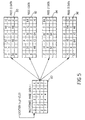
- FIG. 5 a printing example demonstrating the method of the present invention is shown.
- a 4x6 pixel section 80 of the multitoned image signal i is shown.
- a multitone inkjet printer that can produce 5 density levels is used, as indicated by the values 0 through 4 for the multitoned image signal i.
- the multitoned image signal i is created by the image preprocessor 10 of FIG. 1.
- four swaths 90, 92, 94, 96 of the printhead image signal o are shown which were created according to the present invention using the pass table of FIG. 3 and the mask table of FIG. 4.
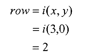
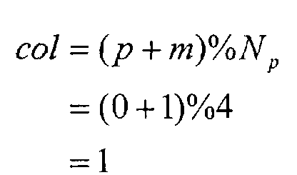
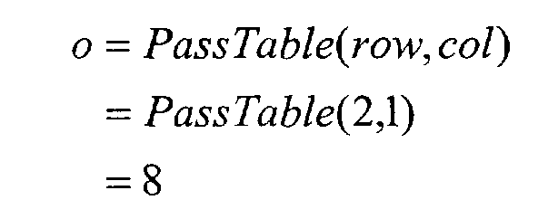
- the row index of the pass table is computed according to EQ 2: On the first pass, the first pass index p has a value of 0, and the column index is computed according to EQ 3: The printhead image signal o value for pass 0 is then retrieved from the pass table according to EQ 4: On the next 3 passes, the first pass index p has the values 1,2, and 3, respectively. This results in column indexes of 2,3, and 0, respectively, as computed by EQ 3. The corresponding printhead image signal o values are 0, 0, and 32, respectively, as computed by EQ 4.
- the multitoned image signal i value of 2 is converted to printhead image signal o values of 8,0,0,32 as shown in the lower left corner of the four swaths 90, 92, 94, 96 of FIG. 5.
- the four swaths of the printhead image signal o are conceptually printed (for demonstration purposes) on four consecutive motions of the printhead over the same region of the page, there are other methods of interlacing the swaths to which the present invention applies equally well.
- the page rather than having the printhead pass over the same region on the page four times before the page is moved, the page instead may be advanced by 1/4 th of the printhead height after each pass. This is described in the prior art references to print masking and interlacing referenced above, but was not presented in the description of the present invention in order to more clearly set forth the invention.
- the invention applies equally well to all forms of printing involving print masking or interlaced swath printing.
- each color channel has its own pass table and mask table.
- FIG. 6 another embodiment of the invention is shown in which additional processing has been included to select the pass table that is used in the pass table processor 60.
- This embodiment is useful for printers that are able to print on multiple raster grids to reproduce the image. This is commonly done in inkjet printing when the spacing between the nozzles on the printhead is larger than the desired spacing between pixels on the page.
- a printhead with nozzle spacing of 300 nozzles per inch (NPI) can be used to print an image at 600 dots per inch (DPI) by interleaving four 300 DPI rasters, one of which is called the "reference raster", and the others are called the "shifted rasters”.
- NPI dots per inch
- a shifted raster table processor 120 is used to produce a selection value, r, in response to a shifted raster table 110 and the first pass index, p, which is an integer counter that counts the number of printhead motions across the page, as was described in an earlier embodiment.
- FIG. 7 An example of a shifted raster table 110 is shown in FIG. 7, in which the selection value indicates whether to use a reference raster (0) or a shifted raster (1) for the current print pass. Still referring to FIG.
- a pass table selector 130 receives the selection value r, and selects a pass table to use for this pass from a set of pass tables 100 by simply selecting the pass table that corresponds to the selection value.
- the selected pass table is then received by the pass table processor 60, and the printhead image signal o is computed in the same manner as described in the first embodiment.
- the pass table processor 60 receives a second pass index, p1(y), instead of the first pass index p.
- the second pass index p1(y) is an integer counter that is maintained separately for each row of the image, and simply counts the number of times that a nozzle on the printhead has passed directly over the given row number, y.
- the second pass index is required because the first pass index counts the total number of printhead motions, regardless of which raster the nozzles in the printhead line up with.
Landscapes
- Physics & Mathematics (AREA)
- Engineering & Computer Science (AREA)
- Mathematical Physics (AREA)
- General Engineering & Computer Science (AREA)
- General Physics & Mathematics (AREA)
- Theoretical Computer Science (AREA)
- Ink Jet (AREA)
- Dot-Matrix Printers And Others (AREA)
- Particle Formation And Scattering Control In Inkjet Printers (AREA)
Abstract
Description

Claims (10)
- A method of multipass inkjet printing of images in response to digital images having code values, comprising the steps of:a) providing an inkjet printer capable of printing at least two ink drops at each printing location during different passes, including a printhead which can select at least two different ink drop sizes; andb) selecting a number of passes for producing an image and providing a print mask having mask values which, in each pass, sequentially corresponds to predetermined pixels and, in response to the mask values and the code values of such pixels, operates the inkjet printer to select the ink drop size for each pixel in each pass so that the inkjet printer produces an image.
- The method of claim 1 wherein the inkjet printer is adapted to produce ink drops having different colorants so as to produce a colored image.
- The method of claim 1 wherein the volume of ink is computed for each pixel during each pass to determine the ink drop size which is selected.
- A method of reproducing a digital image containing an array of pixel code values by determining ink volume to be printed at each pixel location on a receiver medium and using an inkjet printer which is capable of multiple print passes, comprising the steps of:a) computing a row index for a first look up table responsive to each pixel code value;b) computing a column index for the first look up table in response to the location of each pixel, a first pass index, and a number of passes so that the first look up table provides information related to the drop size for each pixel for each pass; andc) indexing the first look up table with said row index and column index for each pixel for each pass to determine an ink volume to be printed at the given pixel location; andd) using the inkjet printer to print the ink volume at each pixel location for each pass to reproduce the image.
- The method of claim 4 wherein step b) further includes:i) indexing a second look up table responsive to the given pixel location to produce a mask value, andii) computing the column index of the first look up table in response to the mask value, the first pass index, and the number of passes.
- The method of claim 5 wherein step a) includes:iii) computing a second row index value as the modulo of a row coordinate value of the given pixel location with a number of rows in the second look up table,iv) computing a second column index value as the modulo of a column coordinate value of the given pixel location with a number of columns in the second look up table, andv) indexing the second look up table with the second row index value and the second column index value to produce the mask value.
- The method of claim 5 wherein step b) further includes computing a first value as the sum of the first pass index and the mask value, and computing the column index as the modulo of the first value with the number of passes.
- The method of claim 4 wherein the inkjet printer is adapted to produce ink drops having different colorants so as to produce a colored image.
- A method of reproducing a digital image containing an array of pixel code values by determining ink volume to be printed at each pixel location on a receiver medium and using an inkjet printer which is capable of multiple print passes, comprising the steps of:a) selecting a first look up table from a set of look up tables in response to a first pass index;b) computing a row index for the selected first look up table in response to each pixel code value;c) computing a column index for the selected first look up table in response to the given pixel location, a second pass index, and a number of passes so that the selected first look up table provides information related to the drop size for each pixel for each pass;d) indexing the selected first look up table with said row index and column index for each pixel for each pass to determine an ink volume to be printed at the given location; ande) using the inkjet printer to print the ink volume at each pixel location for each pass to reproduce the image.
- The method of claim 9 wherein the inkjet printer is adapted to produce ink drops having different colorants so as to produce a colored image.
Applications Claiming Priority (2)
| Application Number | Priority Date | Filing Date | Title |
|---|---|---|---|
| US658800 | 2000-09-11 | ||
| US09/658,800 US6454389B1 (en) | 2000-09-11 | 2000-09-11 | Multipass inkjet printing using print masking |
Publications (2)
| Publication Number | Publication Date |
|---|---|
| EP1187061A2 true EP1187061A2 (en) | 2002-03-13 |
| EP1187061A3 EP1187061A3 (en) | 2003-10-29 |
Family
ID=24642752
Family Applications (1)
| Application Number | Title | Priority Date | Filing Date |
|---|---|---|---|
| EP01203270A Withdrawn EP1187061A3 (en) | 2000-09-11 | 2001-08-30 | Multipass inkjet printing using print masking |
Country Status (3)
| Country | Link |
|---|---|
| US (1) | US6454389B1 (en) |
| EP (1) | EP1187061A3 (en) |
| JP (1) | JP2002120387A (en) |
Cited By (2)
| Publication number | Priority date | Publication date | Assignee | Title |
|---|---|---|---|---|
| EP1354719A3 (en) * | 2002-04-17 | 2004-01-02 | Hewlett-Packard Company | Method for ink-jet printing on common household surfaces |
| WO2012045621A1 (en) * | 2010-10-07 | 2012-04-12 | Oce-Technologies B.V. | Method of improving adhesiveness of marking material and receiving medium and a printer |
Families Citing this family (20)
| Publication number | Priority date | Publication date | Assignee | Title |
|---|---|---|---|---|
| US7108344B2 (en) * | 2003-11-03 | 2006-09-19 | Hewlett-Packard Devleopment Company, L.P. | Printmode for narrow margin printing |
| JP2005169736A (en) * | 2003-12-09 | 2005-06-30 | Brother Ind Ltd | Inkjet recording apparatus and inkjet recording method |
| US7168784B2 (en) | 2004-03-30 | 2007-01-30 | Hewlett-Packard Development Company, L.P. | Formation of images |
| US20050219278A1 (en) * | 2004-03-30 | 2005-10-06 | Hudson Kevin R | Image formation with a flexible number of passes |
| US9299196B2 (en) * | 2004-12-22 | 2016-03-29 | Pitney Bowes Inc. | Method and system for high speed printing using drop-on demand technology that compensates for droplet satellites |
| US7715043B2 (en) | 2006-02-24 | 2010-05-11 | Eastman Kodak Company | Multilevel print masking method |
| US7387361B1 (en) | 2007-02-16 | 2008-06-17 | Eastman Kodak Company | Failed nozzle correction system and method for borderless printing |
| US20090033694A1 (en) * | 2007-07-31 | 2009-02-05 | Yang Shi | Printer control system and method for artifact free and borderless printing |
| US9041978B2 (en) * | 2007-11-24 | 2015-05-26 | Hewlett-Packard Development Company, L.P. | Selecting printing masks optimized for line features and area fill features of image data |
| US8272710B2 (en) * | 2008-07-16 | 2012-09-25 | Eastman Kodak Company | Bi-directional print masking |
| JP2010179576A (en) * | 2009-02-06 | 2010-08-19 | Seiko Epson Corp | Dot recording system, dot recording method, and computer program |
| JP2011000826A (en) * | 2009-06-19 | 2011-01-06 | Canon Inc | Method for encoding record mask, recording method, and recorder |
| JP2012040781A (en) * | 2010-08-19 | 2012-03-01 | Canon Inc | Recording apparatus and processing method for the same |
| WO2014117815A1 (en) * | 2013-01-29 | 2014-08-07 | Hewlett-Packard Development Company, L.P. | Printer and method of processing an image to be printed |
| TWI584968B (en) * | 2015-10-21 | 2017-06-01 | 星雲電腦股份有限公司 | Printing method for uv inkjet printer capable of eliminating printing defects |
| EP3455074B1 (en) | 2016-10-24 | 2021-06-16 | Hewlett-Packard Development Company, L.P. | Depositing print agent |
| KR20190105628A (en) | 2017-04-14 | 2019-09-17 | 휴렛-팩커드 디벨롭먼트 컴퍼니, 엘.피. | Delay Factor for Activation Signal |
| US11216707B2 (en) | 2017-04-14 | 2022-01-04 | Hewlett-Packard Development Company, L.P. | Mask registers to store mask data patterns |
| US10994531B2 (en) | 2017-04-14 | 2021-05-04 | Hewlett-Packard Development Company, L.P. | Drop weights corresponding to drop weight patterns |
| WO2018194675A1 (en) | 2017-04-21 | 2018-10-25 | Hewlett-Packard Development Company, L.P. | Printing within defined zones |
Family Cites Families (4)
| Publication number | Priority date | Publication date | Assignee | Title |
|---|---|---|---|---|
| JP3576694B2 (en) * | 1996-04-23 | 2004-10-13 | キヤノン株式会社 | Ink jet recording method, apparatus thereof, image processing method, and printing method for executing image processing method |
| US6193347B1 (en) * | 1997-02-06 | 2001-02-27 | Hewlett-Packard Company | Hybrid multi-drop/multi-pass printing system |
| US5912683A (en) * | 1997-08-25 | 1999-06-15 | Lexmark International, Inc. | Method of printing with an ink jet printer using an enhanced horizontal resolution |
| US6441922B1 (en) * | 1998-10-31 | 2002-08-27 | Hewlett-Packard Company | Reduction of banding in incremental printing, through selection among colorimetric equivalents |
-
2000
- 2000-09-11 US US09/658,800 patent/US6454389B1/en not_active Expired - Lifetime
-
2001
- 2001-08-30 EP EP01203270A patent/EP1187061A3/en not_active Withdrawn
- 2001-09-10 JP JP2001274165A patent/JP2002120387A/en active Pending
Cited By (2)
| Publication number | Priority date | Publication date | Assignee | Title |
|---|---|---|---|---|
| EP1354719A3 (en) * | 2002-04-17 | 2004-01-02 | Hewlett-Packard Company | Method for ink-jet printing on common household surfaces |
| WO2012045621A1 (en) * | 2010-10-07 | 2012-04-12 | Oce-Technologies B.V. | Method of improving adhesiveness of marking material and receiving medium and a printer |
Also Published As
| Publication number | Publication date |
|---|---|
| EP1187061A3 (en) | 2003-10-29 |
| JP2002120387A (en) | 2002-04-23 |
| US6454389B1 (en) | 2002-09-24 |
Similar Documents
| Publication | Publication Date | Title |
|---|---|---|
| US6454389B1 (en) | Multipass inkjet printing using print masking | |
| US8272710B2 (en) | Bi-directional print masking | |
| WO2007100476A2 (en) | Multi-level printing masking method | |
| EP0709214B1 (en) | Ink jet recording apparatus and method using plural types of ink | |
| US6354689B1 (en) | Method of compensating for malperforming nozzles in a multitone inkjet printer | |
| EP1059803B1 (en) | Image recording apparatus and image recording method | |
| US7303247B2 (en) | Ink jet printing method and ink jet printing system | |
| JPH0946522A (en) | Image processing method, printing device, and display device | |
| US7631955B2 (en) | Printing system and printing method | |
| EP1288002B1 (en) | Method and apparatus of optimizing discrete drop volumes for multidrop capable inkjet printers | |
| EP2233302A9 (en) | Inkjet printer and printing method | |
| EP1288003A1 (en) | An ink jet printer with improved dry time | |
| EP0944024B1 (en) | Reduction of periodic artifacts in incremental printing | |
| US5832184A (en) | Image processing apparatus and method | |
| US6886912B2 (en) | Method and apparatus for processing images having color combinations | |
| US7031021B1 (en) | Randomized superpixels to enhance multilevel image quality in economical, fast incremental-printing error diffusion | |
| JP7552189B2 (en) | Recording control device and recording control method | |
| EP1288001A1 (en) | Method and apparatus for increasing the number of available printing gradations on an ink jet printer | |
| JPH1086503A (en) | Color image processor | |
| JP2012250522A (en) | Image processing apparatus, image forming apparatus, and image processing method | |
| JP2011042048A (en) | Image processor, recording apparatus, and image processing method | |
| US6739772B2 (en) | Printing method and apparatus | |
| JP2005088579A (en) | Inkjet recording method, inkjet recording apparatus, and inkjet recording system | |
| EP2619971B1 (en) | Method of halftoning for asymetric print resolutions and a printer | |
| US12045521B1 (en) | Halftone modification mechanism |
Legal Events
| Date | Code | Title | Description |
|---|---|---|---|
| PUAI | Public reference made under article 153(3) epc to a published international application that has entered the european phase |
Free format text: ORIGINAL CODE: 0009012 |
|
| AK | Designated contracting states |
Kind code of ref document: A2 Designated state(s): AT BE CH CY DE DK ES FI FR GB GR IE IT LI LU MC NL PT SE TR |
|
| AX | Request for extension of the european patent |
Free format text: AL;LT;LV;MK;RO;SI |
|
| PUAL | Search report despatched |
Free format text: ORIGINAL CODE: 0009013 |
|
| AK | Designated contracting states |
Kind code of ref document: A3 Designated state(s): AT BE CH CY DE DK ES FI FR GB GR IE IT LI LU MC NL PT SE TR |
|
| AX | Request for extension of the european patent |
Extension state: AL LT LV MK RO SI |
|
| RIC1 | Information provided on ipc code assigned before grant |
Ipc: 7H 04N 1/40 B Ipc: 7G 06K 15/10 A |
|
| 17P | Request for examination filed |
Effective date: 20040403 |
|
| AKX | Designation fees paid |
Designated state(s): DE FR GB |
|
| STAA | Information on the status of an ep patent application or granted ep patent |
Free format text: STATUS: THE APPLICATION HAS BEEN WITHDRAWN |
|
| 18W | Application withdrawn |
Effective date: 20060214 |