EP1186943A2 - Apparatus for exposing sensitometric and bar code data onto photosensitive media - Google Patents
Apparatus for exposing sensitometric and bar code data onto photosensitive media Download PDFInfo
- Publication number
- EP1186943A2 EP1186943A2 EP01202882A EP01202882A EP1186943A2 EP 1186943 A2 EP1186943 A2 EP 1186943A2 EP 01202882 A EP01202882 A EP 01202882A EP 01202882 A EP01202882 A EP 01202882A EP 1186943 A2 EP1186943 A2 EP 1186943A2
- Authority
- EP
- European Patent Office
- Prior art keywords
- light
- controller
- light source
- film
- optical fibers
- Prior art date
- Legal status (The legal status is an assumption and is not a legal conclusion. Google has not performed a legal analysis and makes no representation as to the accuracy of the status listed.)
- Withdrawn
Links
Images





Classifications
-
- G—PHYSICS
- G03—PHOTOGRAPHY; CINEMATOGRAPHY; ANALOGOUS TECHNIQUES USING WAVES OTHER THAN OPTICAL WAVES; ELECTROGRAPHY; HOLOGRAPHY
- G03C—PHOTOSENSITIVE MATERIALS FOR PHOTOGRAPHIC PURPOSES; PHOTOGRAPHIC PROCESSES, e.g. CINE, X-RAY, COLOUR, STEREO-PHOTOGRAPHIC PROCESSES; AUXILIARY PROCESSES IN PHOTOGRAPHY
- G03C11/00—Auxiliary processes in photography
- G03C11/02—Marking or applying text
-
- G—PHYSICS
- G03—PHOTOGRAPHY; CINEMATOGRAPHY; ANALOGOUS TECHNIQUES USING WAVES OTHER THAN OPTICAL WAVES; ELECTROGRAPHY; HOLOGRAPHY
- G03B—APPARATUS OR ARRANGEMENTS FOR TAKING PHOTOGRAPHS OR FOR PROJECTING OR VIEWING THEM; APPARATUS OR ARRANGEMENTS EMPLOYING ANALOGOUS TECHNIQUES USING WAVES OTHER THAN OPTICAL WAVES; ACCESSORIES THEREFOR
- G03B17/00—Details of cameras or camera bodies; Accessories therefor
- G03B17/24—Details of cameras or camera bodies; Accessories therefor with means for separately producing marks on the film, e.g. title, time of exposure
Definitions
- the present invention relates to sensitometry and more particularly to apparatus for exposing sensitometric and bar code data onto photosensitive media in a manufacturing environment.
- U.S. Patent No. 5,075,716 issued December 24, 1991 to Jehan et al. shows apparatus for exposing reference calibration patches on photosensitive media that includes a light source, and a bundle of optical fibers for transporting light from the light source to the photosensitive medium.
- the exposures to the photosensitive medium are controlled by providing groups of fibers having different numbers of fibers in each group and by apparatus for adjusting the spacing between the fiber bundles and the exposure plane. Furthermore, the exposure is accomplished by contacting the surface of the photosensitive medium with the print head of the apparatus to precisely locate the exposure plane and minimize flare.
- a further problem relates to the size of both the conventional sensitometric apparatus and the size of the exposures produced thereby. It would be desirable to locate the sensitometer for exposing reference calibration patches into the manufacturing equipment of the photosensitive materials, where space is at a premium, to provide the most accurate placement of the patches and maximize the manufacturing system performance.
- sensitometric exposure device It is also desirable to locate the sensitometric exposure device along with a barcode exposure device for the purpose of printing associated metadata and controlling both devices with a central control system
- sensitometer that is easy to set up, reliably maintains its calibration in the manufacturing environment, and can automatically setup to meet the exposure needs of various product types without interrupting the process flow.
- a further need is to provide a sensitometer that is capable of reliably providing millions of exposures without failure or adjustment.
- an apparatus for exposing reference calibration patches onto photosensitive medium including: a light source; a plurality of optical fibers, one fiber for each element to be exposed; a light collector having an input port for receiving light emitted by the light source and an output port for delivering light to one end of the optical fibers; a plurality of light attenuators located with respect to the optical fiber for individually attenuating the light transmitted by each fiber; a projection print head located at the other end of the optical fibers for directing light from the fiber onto the photosensitive medium; and a controller connected to the light source for measuring and controlling the light output of the light collector.
- the apparatus includes a data printer having: a second light source; a two dimensional liquid crystal light modulator for modulating the light from the second light source; optics for projecting an image of the light modulator onto the photosensitive medium; and the controller being connected to the light modulator and the light source for applying a two dimensional bar code image signal to the light modulator and activating the light source for exposing the two dimensional bar code onto the photosensitive medium.
- the apparatus operates as a system that prints both barcode data and sensitometric information on the photosensitive medium transported under the print heads located on a web transport of a photosensitive medium manufacturing machine.
- the apparatus of the present invention has the advantage of providing: a broad dynamic exposure range of up to 4 Log E; rapid exposure times regardless of film type; non-contact printing, whereby no part of the apparatus contacts the photosensitive and fragile film surface; precise, controllable, adjustable exposures; a reference calibration patch profile with a substantially flat profile shape at peak values along with a minimal flare skirt; and a precision of exposure of better than 1% over an 8x range of film speeds and product sensitivities.
- the apparatus is located on a perforation/printing station of a film manufacturing machine at a specific location where a predetermined frame stops, regardless of film length, thus allowing one fixed location printer system to generate various film lengths without need for operator intervention or setup for film length changes on the station.
- the printer control system allows for more efficient and reliable data transfer from the reference calibration patch printer to the bar code data printer. This allows the barcode data printer the capability of reporting on certain characteristics of the reference calibration patch printer and including that info in the data printed by the bar code printer.
- Minimum space is required for implementation on a production manufacturing machine and a minimum impact on present spooler control system during printing, and can be configured for projection printing on a planar or radiused film surface. Its modular design provides for minimized setup and install time.
- the preferred XENON illumination sources provide long life, stable and high reliability compared to tungsten or other sources.
- optical fibers allow for the transport of precise signals through an electromagnetically noisy machine space.
- Separating light source from the print head and joining them with optical fibers allows for flexible placement of the print head on the machine, and easy replacement of the light source or print head.
- Communications between the printer control system with the web transport control system allows for filmstrips with the same data message to be identified by cartridge ID and other specific data.
- the identification information can be stored in the factory. This identification can be used to provide data corrections or updates by communicating the updates to the photofinisher and using the identification information printed in the data and located on the cartridge to identify the affected filmstrips.
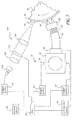
- apparatus for exposing reference calibration patches to form a latent image onto photosensitive medium includes a light collector such as an integrating sphere 12, having a plurality of apertures.
- a pair of flash lamps 14 and 16, preferably Xenon flash lamps, are located in two of the apertures, and an attenuator filter plug 18 is located in another of the apertures.
- Each flash lamp 14 and 16 is connected to a power supply 43 and 42 respectively and can be caused to emit one pulse of light when triggered by controller 20.
- Attenuator filter plug 18 captures light exiting integrating sphere 12 and transfers it into multiple reference calibration patch optical fibers 23, as well as multiple exposure control optical fibers 38.
- a spectrophotometer 17 is inserted into an additional aperture in integrating sphere 12 to collect information on the spectral energy distribution of the exposure light and relay it to controller 20.
- Exposure control optical fibers 38 sample the exposure light and transfer it to exposure integrator circuit 40 which interfaces with controller 20 to control the exposure level as will be detailed later.
- Optical fibers 23 transmit the light from integrating sphere 12 to projection printhead assembly 26 which can be located distant from the rest of reference calibration patch exposure apparatus 10.
- Optical fibers 23 are preferably multimode optical fibers such as 2 mm diameter PMMA (poly-methyl-methyl acrylate) plastic fibers manufactured by Mitsubishi Rayon and known as type ESKATM.
- Projection printhead assembly 26 is located in a fixed location relative to photosensitive media 34 which is in contact with photosensitive media transport and indexing drum 36.
- Projection printhead assembly 26 consists of projection printhead body 27 into which optical fibers 23 enter. The end of optical fiber 23 is polished and held a fixed distance from the surface of media 34 by projection printhead body 27.
- Projection printhead lens 30 focuses an inverted image of the end of optical fiber 23 onto media 34 at substantially 1:1 magnification.
- Lens 30 is preferably a simple symmetric bi-convex lens of BK-7 glass with a first surface radius of 1.5 mm, a second surface radius of-1.5 mm and a thickness of 3-mm.
- Lens 30 is also preferably coated with an anti-reflection coating optimized for broadband white light in the 400-700 nm region.
- a projection printhead input baffle 28 whose function is to trap non-image light rays and stop them from creating flare light at the image plane.
- Baffle 28 is formed by steps 25 that are provided with a non-reflective surface such as black anodization or light absorbing paint that assists in trapping non-image light rays.
- a projection printhead glare stop aperture 32 Between lens 30 and the image plane on the surface of media 34 is a projection printhead glare stop aperture 32.
- the function of glare stop aperture 32 is to stop any non-image light from forming glare around the exposed image.
- a hollow projection printhead output chamber 31 is formed between the second surface of lens 30 and glare stop aperture 32.
- Fig. 2 illustrates an arrangement of latent image exposures on an APS format photographic element.
- the APS system reserves specific areas on the photographic element for use by photofinishing apparatus. These areas can be used for exposing reference calibration patches, and other data used in the photofinishing process.
- an APS format photographic element 70 comprising a strip of photosensitive media 34, according to the Redbook specification, is shown.
- the film strip includes a first reserved frame 72 (known as "Frame 0") reserved for use in photofinishing apparatus and outside the customer image area.
- Perforation 84 is provided adjacent to frame 0 72 on the film strip 70 and locates the position of frame 0 72 along the filmstrip.
- two latent images are exposed in frame 0 72 .
- These are a reference calibration patch array 76 consisting of a plurality of reference calibration patches 82, and a 2D Barcode symbol array 74 consisting of an arrangement of 2D barcode symbols 78. Both arrays 76 and 74, are arranged as shown in Fig 2 within a second reserved area 80, located within frame 0 72. Other arrangements of the arrays are possible.
- Fig. 3 shows a perspective view of the projection printhead assembly 26.
- Printhead assembly 26 consists of a printhead body 27 connected to a plurality of optical fibers 23.
- the optical fibers 23 are collected into optical fiber bundle 50.
- Light energy transmitted through an optical fiber 23 into the printhead body 27 passes through the body 27 to exit the head via a projection printhead glare stop aperture 32 and on to the photosensitive media 34 (not shown).
- An antireflective surface 48 on the printhead body 27 reduces reflections of the light energy between the media 34 and the opposing surfaces of printhead body 27.
- a surface coating such as a Sherwin Williams Co Flat Black E61 Series Epoxy enamel with 0-5% Gloss, alternatively or in combination with a diffuse surface texture, such as resulting from bead blasting the surface.
- Fig. 4 illustrates the attenuation filter plug Assembly 18.
- Plug assembly 18 consists of a attenuation filter plug body 19 connected to a plurality of reference calibration patch optical fibers 23 and exposure control optical fibers 38 with the optical fibers 23 collected into optical fiber bundle 50.
- Light energy collected in the integrating sphere 12 passes into the filter plug assembly 18 through the optical color correction filter 24 and through aperture mask 54 and into the individual attenuation filters 22 before passing finally into the fiber optics 23.
- Aperture mask 54 is aligned with the plurality of individual attenuation filters 22 such that each attenuation filters 22 is aligned with an individual aperture in the aperture mask 54 to insure that light does not leak around the edges of the attenuation filters 22.
- the attenuation filters 22 are preferably a stable optical neutral density filter such as InconelTM on glass, or other material as known in the art.
- Color correction filter 24 is also preferably a stable optical filter material such as a Schott FG type glass or similar material as known in the art. Retaining ring 52 holds filter 24 and mask 54 in place in a recess formed in plug body 19.
- Fig. 5 is a partial cross sectional view further describing the filter plug assembly 18 described in Fig. 4 and showing its internal construction.
- Light energy collected in the integrating sphere 12 passes into the filter plug assembly 18 through optical color correction filter 24 located on one end of the plug body 19.
- Optical correction filter 24 is used to adjust the spectrum of light passed through individual attentuation filters 22 by attenuating particular undesirable wavelengths such that a desired color spectrum is achieved.
- This color corrected light then passes through aperture mask 54 and through the array of individual attenuation filters 22 and into optical fiber 23.
- Each attenuation filter 22 has a unique optical neutral density or color resulting in a unique latent image exposure level for each reference calibration patch 82 as shown in Fig. 2.
- the reference calibration patches produced by this system can be neutral, colored or any combination thereof.
- a data printer for exposing bar code data symbols onto photosensitive medium, includes illumination source 108, preferably a Xenon flash with suitable reflector (not shown), driven by power supply 112 further controlled by a controller 20.
- the controller 20 uses various control inputs in its operation, including those from overall machine controller 134. For example, the machine controller 134 sends timing information to trigger the flash as well as apparatus calibration and setup information to controller 20.
- the illumination source 108 directs uniform illumination into a fiber optic bundle 114.
- the fiber optic bundle 114 directs the illumination to pass through color correction filter 118 housed in housing 116.
- Housing 116 contains a plurality of filters arranged in a manner that allows them to be individually introduced in front of the fiber optic bundle 114 by rotation of housing 116.
- Housing 116 is attached at its center to the shaft of motor 120 allowing it to be rotated by motor 120 .
- Motor 120 is controlled by signals from controller 20.
- Illumination passing through filter 118 passes through condenser optics 124 and toward light valve array 126, preferably a liquid crystal device (LCD) array.
- Light valve array 126 has a plurality of individually addressable pixels for selectively blocking or transmitting illumination to form characters and specific geometry in response to the address and energization of the individual pixels.
- the light valve array 126 is driven by video driver 125 and the driver 125 driven by controller 20 via control line 132.
- Illumination passing light valve array 126 forms an image that passes further through focusing optics 128 to be focused down to the imaging position 130 on the photosensitive medium 34 forming a latent image.
- Photosensitive media 34 is supported and transported on the photosensitive media transport and indexing drum 36 of a web transport device.
- the photosensitive media is held to the indexing drum 36 by means of a suitable traction inducing device (not shown), for example a vacuum generated between the media and drum or a nip roll compressing the media against the drum 36
- the printer receives setup information from machine controller 134 that is passed to the controller 20.
- This information for example, film strip length and film product code, is used to select the correct color correction filter 116 and rotate it into place via motor 120 as well as set up the proper level and duration of illumination source 108.
- the indexing drum 36 moves photosensitive media 34 into the proper location along the media to the imaging position 130 shown in Fig. 6. Indexing drum 36 is then directed to stop motion by machine controller 134.
- Machine controller 134 recognizes that photosensitive media 34 is in position and directs controller 20 to flash illumination source 108 via power supply 112. The illumination passes through the system, generating an image at light valve 126 that is focused onto the photosensitive media at imaging position 130 and completing the cycle. Indexing drum 36 is then directed by machine controller 134 to begin the next cycle of operation and move to the next filmstrip position.
- FIG. 7 the interconnection of both the reference calibration patch printer 10 and data printer 100 is illustrated. Note that not all parts are shown for both printers; refer to Figs. 1 and 6 for full details.
- Power supply 112 triggered by a signal from controller 20, flashes illumination source 108 whose light is collected by condenser optics 124 and modulated by light valve array 126.
- the spatial pattern used to modulate the light is generated by controller 20 in response to data from machine controller 134.
- Focusing optics 128 images the modulated light from light valve 126 onto photosensitive media 34 held on photosensitive media transport and indexing drum 36 forming 2D barcode symbol array 74. Adjacent to symbol array 74 is reference calibration patch array 76 formed by reference calibration patch printer 10.
- Controller 20 commands power supplies 42 and 43 to activate flash lamps 14 and 16 as will be described in detail later. Controller 20 uses photosensitive media sensitivity data from machine control 134 as well as data from exposure integrator circuit 40 to build an accurate latent image exposure through integrating sphere 12 and projection printhead assembly 18. Both reference calibration patch printer 10 and data printer 100 are commanded to make exposures when photosensitive media 34 and media transport and indexing drum 36 are substantially stopped as communicated by machine control 134.
- Optical fibers 38 deliver light energy from integrating sphere 12 to photosensors 136 and 138.
- Photosensors 136 and 138 are preferably silicon photodiodes.
- Exposure integrator circuit 40 contains two redundant channels labeled "A" and "B". To enhance reliability, photosensors 136 and 138 are preferably of similar functional capabilities, but from different manufacturers, thus reducing the probability of both failing or degrading at the same rate.
- analog integrator circuits 140 and 142 As light energy is captured by the photodiodes an electrical current is produced and integrated by analog integrator circuits 140 and 142. Analog integrator circuits are well known in the art and one example is Burr Brown Part #IVC102, Arlington AZ.
- the output of the integrator circuits is applied to the input of analog to digital converters 144 and 146.
- Analog to digital converters 144 and 146 are shown as having 16 bit parallel digital data outputs, but converters with different resolution and/or serial outputs may be made to work as well.
- a 16 bit bi-directional digital data bus 152 connects the converters with controller 20 shown in Fig. 1.
- a control signal bus 150 connects controller 20 with converters 144 and 146, and integrators 140 and 142. Individual control signals are provided to reset integrators 140, 142 and to enable the output of converters 144, 146 .
- Also present on the exposure integrator circuit 40 is a nonvolatile memory 148.
- Non-volatile memory 148 is connected to controller 20 via data bus 152 and control signal bus 150. Read and write control lines connect non-volatile memory 148 with CPU 20 via signal bus 150.
- a temperature compensation mechanism comprised of temperature sensor 154, temperature controller 156, heater 158, and heatsink 160.
- Photosensors 136 and 138, and temperature sensor 154 are tightly coupled thermally to heatsink 160 such that they are all at substantially identical temperatures.
- Temperature controller 156 senses this temperature via temperature sensor 154 and applies power as necessary to heater 158 to maintain a constant temperature just slightly above the ambient temperature. This mechanism corrects for the temperature-induced drift in the sensitivity of photosensors 136 and 138.
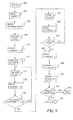
- the second step is to retrieve a target exposure value from non-volatile memory 148 (shown in Fig. 8), as shown in step 164. Different target exposure values will be determined by calibration and stored in memory 148, one target value for each film speed.
- the next step in the sequence consists of resetting the integrator circuits 140 and 142 in Fig. 8, as shown in step 166.
- a "major" flash pulse is generated by triggering flash lamp power supply 43 in Fig. 1, as shown in step 168 .
- a reading is made by transferring the digital data from analog to digital converter "A" 144 in Fig.
- Step 172 illustrates the calculation of an intermediate variable "stepsize" by dividing the reading from the analog to digital converter by the target value.
- the next step, shown in step 174 is to cause another major flash lamp pulse to be generated.
- step 176 by reading the analog to digital converter value.
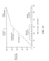
- Fig. 10 illustrates graphically one method of building the integrated exposure.
- the target value (which is fixed), the integrated exposure (equivalent to the analog to digital converter output), and the individual major and trimming flashes (equivalent to the photosensor output) are plotted versus time.
- the integrated exposure increases in large steps to quickly approach the final target. From here on, the exposure increases slowly in smaller steps to achieve very fine accuracy of exposure.
- step 180 by causing a trimming flash to be generated by flash lamp power supply 42 and flash lamp 16.
- step 182 the output of the analog to digital converter is read.
- Step 184 shows the comparison of the latest reading to the target value, as long as the reading is less than the target the sequence returns to step 180 and continues to flash. After the reading exceeds the target value, flashing stops and the sequence proceeds to step 186. It can be seen that by adjusting the trimming flash level it is possible to achieve the integrated exposure level within a resolution of +/- 1 trimming flash energy unit.
- step 186 the value generated by the second or "B" channel is read. By reading the output from analog to digital converter 146 and subtracting it from the target value in step 188 an error value is generated.
- step 190 the absolute value of the error value is formed in step 190.
- step 192 the error value is compared to a predetermined tolerance and the sequence ends in either success or failure in steps 196 and 194 respectively.
- the large and small exposures can be performed simultaneously to reduce the exposure time.
- a concern in the manufacturing environment is that of contamination entering the glare stop aperture 32 and settling on the printhead lens 30 in the projection printer assembly 26 of the reference calibration patch Printer 10 effectively blocking or degrading the projected illumination.
- This contamination may consist of chips or flakes of photosensitive media 34 generated as the result of the perforating process, or other cutting processes not illustrated here, and left loosely attached to the media 34. Interactions between the media 34 and a perforator/printer station of a web transport 240 (see Fig. 14) may cause this loosely attached contamination to become dislodged from media 34 and thrown into the glare stop aperture 32.
- Another source of contamination is from maintenance activities in the area near the printhead assembly 26. Cleaning solvents, and other contaminates used during maintenance may be inadvertently directed toward the glare stop aperture 32 possibly blocking or degrading the projected image.
- the contamination may be very difficult to clean away due to the plurality of apertures 34 and general construction of the printhead body 27.
- a printhead apparatus that allows for easy removal of contamination would be desirable.
- An apparatus for protecting the glare stop aperture 32 and printhead lens 30 from being contaminated is also desirable.
- a moveable cover 96 is supported by cover bearing 90 attached to the projection printhead body 27.
- Moveable cover 96 is retracted into a position exposing the plurality of glare stop apertures 32 by cover actuator 97 connected to support 94.
- Cover actuator 97 may be an electrical solenoid or similar device activated by the overall machine controller 134.
- a cover return spring 92 urges the moveable cover 96 into the extended position covering the plurality of glare stop apertures 32 when the actuator 97 is de-energized, thus providing contamination protection by shielding the plurality of glare stop apertures 32 from the environment.
- FIG. 12 An alternative arrangement is shown in Fig. 12 where a fixed transparent cover 98 with antireflective surfaces is attached to the front of the printhead body 27 in a position that covers the plurality of glare stop apertures 32. This cover remains in place at all times shielding the plurality of glare stop apertures 32 from the environment and providing a front surface that can be easily cleaned if contaminated.
- FIG. 13 Another alternative arrangement is shown in Fig. 13 where the contamination is prevented from entering the plurality of glare stop apertures 32 by means of a continuous flow of pressurized air exiting from each aperture 32.
- Projection printhead body 27 containing the plurality of optical fibers 23, input baffle 28, lens 30, and glare stop aperture 32 are configured as shown in Fig. 13.
- a small output chamber 31 is formed between aperture 32 and lens 30 by the assemblage of the components as shown.
- One end of delivery channel 204 is ported into the sidewall of the chamber 31 as shown, and the other end is connected to delivery tube 202.
- Tube 202 is further connected to a pressurized air source 200 which supplies a constant flow of clean pressurized air to tube 202.
- the air continuously flowing out of glare stop aperture 32 and along air flow path 206 effectively prevents typical environmental contamination from entering the plurality of glare stop apertures 32, maintaining the imaging performance of printhead assembly 26
- Fig. 14 illustrates the arrangement of the entire printing system consisting of the perforator/printer station of a web transport 240, the reference calibration patch printer 10, and data printer 100 as well as associated control connections.
- Printers 10 and 100 are designed to produce the reference calibration patch array 76 and 2D barcode symbol array 74 in frame 0 72 relative to perforation 84 in a photographic element 70 as shown in Fig. 2.
- Media 34 is supported by web transport rollers (not shown) and rotatable indexing drum 36 such that it passes between fixed perforator die 232 and moveable perforator punch support 226 of perforator assembly 238.
- Support 226 moves in a linear fashion and contains a plurality of punches 224 that are used to generate perforations in the film, such as perforation 84, when the punch 224 is moved into engagement with the fixed perforator die 232 through the motion of support 226.
- the support 226 is moved linearly by actuator link 228 that is attached to actuator 230.
- Actuator 230 may, for example, be a servo motor driving an eccentric linkage connected to support 226.
- Actuator 230 receives signals from overall machine controller 134 to start and stop a cycle of motion that corresponds to a perforation cycle where punch 224 and fixed perforator die 232 operate to form a perforation or plurality of perforations in the media 34.
- Suction box 220 operates under subatmospheric pressure generated by a vacuum source (not shown) drawing air through exhaust pipe 222.
- Reference calibration printer 10 mounted on the station 240 in a position radially and circumferentially located over indexing drum 36 is actuated by a power supply 43 and 42 and further controlled by controller 20.
- Printers 10 and 100 are further mechanically located with respect to each other to assure precise placement of the reference calibration patch array 76 and the 2-D barcode data symbol array 74.
- Perforator/printer station common exposure location 236 represents a location whereby frame 0 72 and adjacent perforation 84 are located for any filmstrip length of an APS photographic element 70 consisting of media 34 supported on indexing drum 36 during operation of the station 240.
- Location 236 further represents the printing location on media 34 for printers 10 and 100 regardless of filmstrip length. It further represents the position where the indexing velocity of indexing drum 36 supporting media 34 is zero during the time in the perforation cycle when the punch 224 is engaged in the media 34.
- a strip of photosensitive media 34 is converted to a useable format by adding perforations and edge printing. This may be done on a perforator/ printer station of a web transport 240 as shown in Fig. 14.
- An example is the perforation 84 found on APS format photographic element 70 and shown in Fig. 2.
- the perforation 84 is provided adjacent to frame 0 72 on the film strip 70 and locates the position of frame 0 72 along the filmstrip.
- the intention of this apparatus is to provide capability to add two additional features to frame 0 72.
- These are a sensitometric exposure element array 76 consisting of a plurality of reference calibration patches 82 and a 2D barcode symbol array 74 consisting of an arrangement of 2 D barcode symbols 78. Both arrays 76 and 74 are arranged as shown in Fig. 2 within a second reserved area 80, located within frame 0 72.
- the perforation of the filmstrip can be generated using an indexing, incremental motion perforator as is know in the art.
- a punch and die combination generates a perforation pattern in the film, such as media 34, by a series of incremental punching operations where the film is perforated to form a first set of perforations, the punches retract from engagement in the film, the film is indexed ahead to the next perforation position, the film forward velocity is reduced to zero, and the punches engage in the film to begin a new perforating cycle and form a second set of perforations adjacent to the first.
- the film is typically indexed to subsequent positions by a rotatable support device that engages the film in some manner.
- a continuous series of perforations can be generated in this manner as well as a discontinuous series of perforations.
- An example of a discontinuous series of perforations is found on the APS filmstrip, well known in the art, where no perforations are present at the leader and trailer positions along the filmstrip.
- the cycle of operation commences with the media 34 supported on the station 240 is first perforated by the punch 224 while the media is at rest during the dwell time between indexes.
- the punch 224 disengages the media 34 by the action of actuator 230 controlled by controller 134.
- Controller 134 then commands a servo indexing motor (not shown) attached to Indexing Drum 36 to rotate and transport the media 34 out of the perforator assembly 238 until frame 0 72 is located in position on the drum 36 that corresponds to location 236.
- Controller 134 commands the servo indexing motor rotation driving drum 36 to stop rotation and reduce the media 34 velocity to zero.
- the controller 134 then signals the controller 20 of printers 10 and 100 to begin operation while the media 34 is not in motion.
- Controller 134 simultaneously signals the actuator 230 to begin a perforation cycle to generate a second series of perforations adjacent to the first on the same filmstrip. Alternatively the perforation cycle could be the start of a new filmstrip. Controller 20 operates subsystems 10 and 100 and then signals controller 134 when the printing operation is completed. Actuator 230 also signals controller 134 once the perforation cycle is complete. Controller 134 then completes the peroration cycle by commanding the indexing drum 36 servo motor to rotate the drum 36 transporting the media into the next perforation position.
- the printing positional variation for printers 10 and 100 is generally a function of the highly accurate positioning capability of the drum 34 servo motor, resulting in accurate placement of arrays 74 and 76 within second reserved area 80.
- This setup results in a station 240 with the capability of printing to media 34 with highly accurate positioning, during a short ( ⁇ 100msec) duration and with one printer 10 and 100 machine position that can accommodate all filmstrip lengths.
- Fig. 15 is a partial view further describing the attenuation filter plug assembly 18 described in Fig. 5 and further illustrating an alternative apparatus that allows for automatic optical color correction filter adjustment in response to signals from controller 20.
- Light energy collected in the integrating sphere 12 passes into the filter plug assembly 18 through the optical color correction filter 24 located on one end of the plug body 19.
- the correction filter 24 is used to adjust the spectrum of light passed through to the individual attentuation filters 22 by attenuating particular undesirable wavelengths such that a desired color spectrum is achieved. This color corrected light then passes through the array of individual attenuation filters 22 and into fiber optics 23.
- a rotatable color correction filter wheel 60 contains a plurality of correction filters 24 each with individual color correction characteristics interacting with the filter plug assembly as shown in Fig. 15.
- the wheel 60 is attached to the center shaft of rotatable motor 62 that is actuated by controller 20 in response to measurements from spectrophotometer 17 .
- the wheel 60 places an individual color correction filter 24 in front of the of aperture mask 54 and individual optical attenuation filters 22 in the filter plug body 19 of plug assembly 18 as shown in Fig. 15 achieving the desired automatic adjustment of color temperature of the illumination from integrating sphere 12.
- This example illustrates one apparatus for achieving automatic color temperature correction, other arrangements are possible.
Landscapes
- Physics & Mathematics (AREA)
- General Physics & Mathematics (AREA)
- Projection-Type Copiers In General (AREA)
- Printers Or Recording Devices Using Electromagnetic And Radiation Means (AREA)
- Control Of Exposure In Printing And Copying (AREA)
Abstract
Description
Claims (25)
- Apparatus for exposing reference calibration patches onto photosensitive medium, comprising:a) a light source;b) a plurality of optical fibers, one fiber for each element to be exposed;c) a light collector having an input port for receiving light emitted by the light source and an output port for delivering light to one end of the optical fibers;d) a plurality of light attenuators located with respect to the optical fiber for individually attenuating the light transmitted by each fiber;e) a projection print head located at the other end of the optical fibers for directing light from the fiber onto the photosensitive medium; andf) a controller connected to the light source for measuring and controlling the light output of the light collector.
- The apparatus claimed in 1, wherein the controller is connected to the light source by a plurality of optical fibers, and includes a corresponding plurality of redundant light measuring elements and a temperature compensation element for detecting the temperature of the light measuring elements and compensating their output for temperature.
- The apparatus claimed in claim 1, wherein the light source includes a plurality of flash lamps.
- The apparatus claimed in claim 3, wherein the flash lamps include a main flash lamp for providing a major portion of the exposure and a trimming flash. lamp for finely adjusting the exposure.
- The apparatus claimed in claim 1, wherein the print head includes, for each fiber, a light baffle portion, a lens for focusing the end of the fiber onto the medium and a glare stop to reduce flare between reference calibration patches.
- The apparatus claimed in claim 5, wherein the glare stop and lenses include an antireflection coating and the print head includes grooves to reduce reflection from other optical hardware and the photosensitive.
- The apparatus claimed in claim 1 further comprising a transparent cap covering the end of the print head assembly.
- The apparatus claimed in claim 5 wherein the print head assembly includes a space between the lens and the glare stop and further comprising a source of pressurized air connected to the space and exhausting through the glare stop.
- The apparatus claimed in claim 1 further comprising a removable cover for covering the end of the print head assembly when not in use.
- The apparatus claimed in claim 1, wherein the controller operates the light source to produce a plurality of relatively large pulses of light to build up the exposure to less than a desired predetermined amount, and a plurality of relatively smaller pulses of light to complete the exposure to the predetermined amount.
- The apparatus claimed in claim 10, wherein the light source includes a plurality of flash lamps for providing the relatively large and smaller pulses of light respectively.
- The apparatus claimed in claim 1 where the light source is a flash lamp with a quenched driver.
- The apparatus claimed in claim 1, further comprising an automatic color temp correction filter and a spectra-photometer located in the light collector for monitoring the color temperature of the light in the light collector and providing feedback to control the automatic color temp correction filter.
- The apparatus claimed in claim 1, further comprising a spectra-photometer located in the light collector for monitoring the color temperature of the light in the light collector and providing a signal to indicate a color temp shift.
- The apparatus claimed in claim 1, further incorporating a data printer comprising:a) a second light source;b) a two dimensional liquid crystal light modulator for modulating the light from the second light source;c) optics for projecting an image of the light modulator onto the photosensitive medium; andd) the controller being connected to the light modulator and the light source for applying a two dimensional bar code image signal to the light modulator and activating the light source for exposing the two dimensional bar code onto the photosensitive medium.
- The apparatus claimed in claim 15, further comprising a memory connected to the controller for storing correction factors for the reference calibration patches exposed onto the photosensitive medium and the controller including means for generating two dimensional bar code symbol based on the correction factors.
- The apparatus claimed in claim 15, wherein the photosensitive medium is photographic film and the apparatus is mounted on a film transport of a film manufacturing apparatus.
- The apparatus claimed in 17 wherein the film manufacturing apparatus is a perforating/printing station whereby precise placement of the reference calibration patches and 2D barcodes relative to the film perforations is achieved.
- The apparatus claimed in 18 where the controller is connected to and synchronized with a controller of the perforating/printing station such that automatic machine setups when changing product types are enabled, thereby minimizing manufacturing downtime and need for operator intervention.
- The apparatus claimed in 19 wherein the perforating/printing station intermittently slows or stops the photosensitive medium, and the controller causes exposures to be made when the film strip is slowed or stopped.
- The apparatus claimed in claim 16 wherein the correction factors represent the offsets between the desired sensitometric data element values and the actual sensitometric data element values as measured relative to an established standard to fully define the film characteristic at time of manufacture.
- The apparatus claimed in claim 5 wherein the lenses and the optical fibers are configured to produce a substantially flat peak profile.
- The apparatus described in claim 5 wherein the photosensitive medium is on a curved surface, and wherein the optical fibers, light baffles, lenses and glare stops are arranged in the printhead normal to the curved surface and at equal distances therefrom to provide a consistent focus distance for each data element.
- The apparatus claimed in claim 1, wherein the light collector is an integrating sphere.
- The apparatus claimed in claim 20, wherein the perforation/ printing station includes a location where a predetermined frame stops, regardless of film length, wherein the apparatus is at this location.
Applications Claiming Priority (2)
| Application Number | Priority Date | Filing Date | Title |
|---|---|---|---|
| US09/635,389 US6407767B1 (en) | 2000-08-09 | 2000-08-09 | Apparatus for exposing sensitometric and bar code data onto photosensitive media |
| US635389 | 2000-08-09 |
Publications (2)
| Publication Number | Publication Date |
|---|---|
| EP1186943A2 true EP1186943A2 (en) | 2002-03-13 |
| EP1186943A3 EP1186943A3 (en) | 2003-06-04 |
Family
ID=24547605
Family Applications (1)
| Application Number | Title | Priority Date | Filing Date |
|---|---|---|---|
| EP01202882A Withdrawn EP1186943A3 (en) | 2000-08-09 | 2001-07-30 | Apparatus for exposing sensitometric and bar code data onto photosensitive media |
Country Status (3)
| Country | Link |
|---|---|
| US (1) | US6407767B1 (en) |
| EP (1) | EP1186943A3 (en) |
| JP (1) | JP2002086801A (en) |
Cited By (6)
| Publication number | Priority date | Publication date | Assignee | Title |
|---|---|---|---|---|
| FR2854959A1 (en) * | 2003-05-16 | 2004-11-19 | Eastman Kodak Co | Exposure device integrated into camera for writing e.g. images onto photosensitive film in e.g. medical imaging field, has modulator and filter arranged in series in optical trajectory of exposure light originating from light source |
| WO2004114655A1 (en) * | 2003-06-18 | 2004-12-29 | Thomson Licensing S.A. | Apparatus for recording data on motion picture film |
| EP1920279B1 (en) * | 2005-08-09 | 2013-05-22 | The Boeing Company | Systems and methods for distributing signals communicated on fiber optic transmission lines |
| FR3065347A1 (en) * | 2017-04-14 | 2018-10-19 | Phoxene | DEVICE FOR GENERATING LIGHTNING |
| GB2503052B (en) * | 2012-06-13 | 2019-09-18 | Ffei Ltd | Method of communicating calibration data and colour calibration article |
| EP4016188A3 (en) * | 2020-12-18 | 2022-12-07 | Esko-Graphics Imaging GmbH | Process and apparatus for controlled exposure of flexographic printing plates |
Families Citing this family (13)
| Publication number | Priority date | Publication date | Assignee | Title |
|---|---|---|---|---|
| US7113627B1 (en) | 2000-08-09 | 2006-09-26 | Eastman Kodak Company | Location of extended linear defects |
| US6985270B1 (en) * | 2000-08-09 | 2006-01-10 | Eastman Kodak Company | Method and photographic element for calibrating digital images |
| US6882356B2 (en) | 2003-02-11 | 2005-04-19 | Eastman Kodak Company | Method and apparatus for watermarking film |
| CN100334504C (en) * | 2003-02-28 | 2007-08-29 | 罗姆股份有限公司 | Image forming device |
| JP2004338239A (en) * | 2003-05-15 | 2004-12-02 | Konica Minolta Medical & Graphic Inc | Ink jet recorder |
| US6930759B2 (en) * | 2003-09-23 | 2005-08-16 | Eastman Kodak Company | Method and apparatus for exposing a latent watermark on film |
| US7366382B2 (en) * | 2003-10-01 | 2008-04-29 | Photon, Inc. | Optical beam diagnostic device and method |
| FR2861874B1 (en) * | 2003-10-29 | 2006-02-24 | Eastman Kodak Co | METHOD FOR RECORDING AND READING DIGITAL DATA ON A PHOTOGRAPHIC MEDIUM |
| EP2282510A3 (en) * | 2004-05-05 | 2011-03-23 | LaserSoft Imaging AG | Calibration of imaging devices for minimizing individual color reproducing errors of such devices |
| WO2006030597A1 (en) * | 2004-09-17 | 2006-03-23 | Japan Science And Technology Agency | Object digitizing device using integrating sphere wave source |
| WO2007005052A1 (en) * | 2005-06-29 | 2007-01-11 | Thomson Licensing | System and method for film watermarking |
| US7714908B2 (en) | 2006-05-26 | 2010-05-11 | Lifetouch Inc. | Identifying and tracking digital images with customized metadata |
| WO2013186913A1 (en) * | 2012-06-15 | 2013-12-19 | パイオニア株式会社 | Photometric device |
Family Cites Families (18)
| Publication number | Priority date | Publication date | Assignee | Title |
|---|---|---|---|---|
| DE2803380A1 (en) | 1978-01-26 | 1979-08-02 | Agfa Gevaert Ag | DEVICE FOR APPLYING TEST EXPOSURE |
| US4965575A (en) | 1988-10-07 | 1990-10-23 | Eastman Kodak Company | Data alignment circuit and method for self-clocking encoded data |
| JP2567479B2 (en) * | 1988-10-17 | 1996-12-25 | 富士写真フイルム株式会社 | Bar code printing device |
| US4922089A (en) | 1988-12-05 | 1990-05-01 | Eastman Kodak Company | Constant color temperature and intensity illumination source |
| US5075716A (en) | 1990-11-29 | 1991-12-24 | Eastman Kodak Company | Apparatus and method for precisely exposing radiation sensitive materials |
| EP0698453B1 (en) | 1992-12-07 | 2002-04-03 | Fuji Photo Film Co., Ltd. | Perforator |
| EP0623432B1 (en) | 1993-04-08 | 1998-05-20 | Eastman Kodak Company | Apparatus for transporting and perforating elongated strips of material |
| US5400116A (en) | 1993-11-03 | 1995-03-21 | Eastman Kodak Company | Apparatus and method for producing gradated exposures on radiation sensitive material |
| US5452055A (en) | 1994-07-14 | 1995-09-19 | Eastman Kodak Company | Apparatus and method for making a reference exposure on a leading and/or trailing portion of a filmstrip |
| FR2723451B1 (en) * | 1994-08-08 | 1997-05-16 | Kodak Pathe | SPECTRAL SENSITOMETER FOR PHOTOSENSITIVE SURFACE |
| US5563717A (en) * | 1995-02-03 | 1996-10-08 | Eastman Kodak Company | Method and means for calibration of photographic media using pre-exposed miniature images |
| US5767983A (en) | 1995-03-24 | 1998-06-16 | Fuji Photo Film Co., Ltd. | Color copying apparatus for determining exposure amount from image data of an original image and a reference image |
| US5646713A (en) | 1995-06-13 | 1997-07-08 | Eastman Kodak Company | Apparatus and method for exposing data characters onto a strip region of moving photosensitive media |
| US5649260A (en) | 1995-06-26 | 1997-07-15 | Eastman Kodak Company | Automated photofinishing apparatus |
| JPH0961945A (en) * | 1995-08-24 | 1997-03-07 | Noritsu Koki Co Ltd | Photo printing equipment |
| US5598008A (en) * | 1995-10-18 | 1997-01-28 | Lumisys, Inc. | Wavelength selective light collector system |
| US5667944A (en) | 1995-10-25 | 1997-09-16 | Eastman Kodak Company | Digital process sensitivity correction |
| US5799029A (en) * | 1996-05-14 | 1998-08-25 | Sdl, Inc. | Laser system with reduced power fluctuations for employment in applications requiring continuous stable light intensity delivery |
-
2000
- 2000-08-09 US US09/635,389 patent/US6407767B1/en not_active Expired - Fee Related
-
2001
- 2001-07-30 EP EP01202882A patent/EP1186943A3/en not_active Withdrawn
- 2001-08-03 JP JP2001236220A patent/JP2002086801A/en active Pending
Cited By (11)
| Publication number | Priority date | Publication date | Assignee | Title |
|---|---|---|---|---|
| FR2854959A1 (en) * | 2003-05-16 | 2004-11-19 | Eastman Kodak Co | Exposure device integrated into camera for writing e.g. images onto photosensitive film in e.g. medical imaging field, has modulator and filter arranged in series in optical trajectory of exposure light originating from light source |
| WO2004102268A1 (en) * | 2003-05-16 | 2004-11-25 | Eastman Kodak Company | Exposure device with spatial light modulator and neutral density filters |
| US7292314B2 (en) | 2003-05-16 | 2007-11-06 | Eastman Kodak Company | Exposure device with spatial light modulator and neutral density filters |
| WO2004114655A1 (en) * | 2003-06-18 | 2004-12-29 | Thomson Licensing S.A. | Apparatus for recording data on motion picture film |
| US7508484B2 (en) | 2003-06-18 | 2009-03-24 | Thomson Licensing | Apparatus for recording data on motion picture film |
| CN100474907C (en) * | 2003-06-18 | 2009-04-01 | 汤姆森特许公司 | Apparatus for recording data on motion picture film |
| US7894719B2 (en) | 2003-06-18 | 2011-02-22 | Thomson Licensing | Recording data on motion picture film |
| EP1920279B1 (en) * | 2005-08-09 | 2013-05-22 | The Boeing Company | Systems and methods for distributing signals communicated on fiber optic transmission lines |
| GB2503052B (en) * | 2012-06-13 | 2019-09-18 | Ffei Ltd | Method of communicating calibration data and colour calibration article |
| FR3065347A1 (en) * | 2017-04-14 | 2018-10-19 | Phoxene | DEVICE FOR GENERATING LIGHTNING |
| EP4016188A3 (en) * | 2020-12-18 | 2022-12-07 | Esko-Graphics Imaging GmbH | Process and apparatus for controlled exposure of flexographic printing plates |
Also Published As
| Publication number | Publication date |
|---|---|
| JP2002086801A (en) | 2002-03-26 |
| US6407767B1 (en) | 2002-06-18 |
| EP1186943A3 (en) | 2003-06-04 |
Similar Documents
| Publication | Publication Date | Title |
|---|---|---|
| US6407767B1 (en) | Apparatus for exposing sensitometric and bar code data onto photosensitive media | |
| EP0493799B1 (en) | Unibody printing system and process | |
| US7969553B2 (en) | Exposure device with mechanism for forming alignment marks and exposure process conducted by the same | |
| JPH06206309A (en) | Device and method for registering of leaf paper press | |
| JP2006098719A (en) | Exposure apparatus | |
| CN106257247A (en) | Spectroscopic measurement device, image processing system and spectral photometry method | |
| US6305284B1 (en) | Method and apparatus for making an offset printing plate | |
| US20110123934A1 (en) | Scanning exposure apparatus | |
| JPH05246053A (en) | Registration indicia on drum periphery | |
| JP3122332B2 (en) | Film scanner | |
| JPH05201103A (en) | Laser thermal printer with positive air flow | |
| JPH05201035A (en) | Focusing laser diode set on write head | |
| JPH05201034A (en) | Selective winding member in laser thermal printer | |
| EP0710875B1 (en) | Image reading device for photographic printing | |
| EP2144118A1 (en) | Exposure apparatus and method of manufacturing device | |
| GB2196440A (en) | Controlled exposure | |
| JP3226616B2 (en) | Initial setting method of auto focus lens | |
| JP2006116968A (en) | Graphic drawing device capable of drawing graphic on recording material | |
| JP3256284B2 (en) | Thermal image forming equipment | |
| US7292376B2 (en) | Device for digitally generating images | |
| JPH11202419A (en) | Image recording device | |
| US5751334A (en) | Printer with support shoe and media metering therein | |
| JPS61174539A (en) | Photograph printing device | |
| JPH05304589A (en) | Accurate lead screw driving mechanism | |
| KR100444271B1 (en) | Color image forming method and apparatus |
Legal Events
| Date | Code | Title | Description |
|---|---|---|---|
| PUAI | Public reference made under article 153(3) epc to a published international application that has entered the european phase |
Free format text: ORIGINAL CODE: 0009012 |
|
| AK | Designated contracting states |
Kind code of ref document: A2 Designated state(s): AT BE CH CY DE DK ES FI FR GB GR IE IT LI LU MC NL PT SE TR |
|
| AX | Request for extension of the european patent |
Free format text: AL;LT;LV;MK;RO;SI |
|
| PUAL | Search report despatched |
Free format text: ORIGINAL CODE: 0009013 |
|
| AK | Designated contracting states |
Designated state(s): AT BE CH CY DE DK ES FI FR GB GR IE IT LI LU MC NL PT SE TR |
|
| AX | Request for extension of the european patent |
Extension state: AL LT LV MK RO SI |
|
| RIC1 | Information provided on ipc code assigned before grant |
Ipc: 7G 03C 11/02 B Ipc: 7G 03B 27/73 B Ipc: 7G 03B 27/52 A |
|
| 17P | Request for examination filed |
Effective date: 20031128 |
|
| STAA | Information on the status of an ep patent application or granted ep patent |
Free format text: STATUS: THE APPLICATION HAS BEEN WITHDRAWN |
|
| AKX | Designation fees paid |
Designated state(s): DE FR GB NL |
|
| 18W | Application withdrawn |
Effective date: 20040122 |