EP1186919A1 - Optical fiber and optical transmission line comprising the same - Google Patents
Optical fiber and optical transmission line comprising the same Download PDFInfo
- Publication number
- EP1186919A1 EP1186919A1 EP00917325A EP00917325A EP1186919A1 EP 1186919 A1 EP1186919 A1 EP 1186919A1 EP 00917325 A EP00917325 A EP 00917325A EP 00917325 A EP00917325 A EP 00917325A EP 1186919 A1 EP1186919 A1 EP 1186919A1
- Authority
- EP
- European Patent Office
- Prior art keywords
- dispersion
- optical
- transmission line
- wavelength band
- less
- Prior art date
- Legal status (The legal status is an assumption and is not a legal conclusion. Google has not performed a legal analysis and makes no representation as to the accuracy of the status listed.)
- Ceased
Links
Images


Classifications
-
- G—PHYSICS
- G02—OPTICS
- G02B—OPTICAL ELEMENTS, SYSTEMS OR APPARATUS
- G02B6/00—Light guides; Structural details of arrangements comprising light guides and other optical elements, e.g. couplings
-
- G—PHYSICS
- G02—OPTICS
- G02B—OPTICAL ELEMENTS, SYSTEMS OR APPARATUS
- G02B6/00—Light guides; Structural details of arrangements comprising light guides and other optical elements, e.g. couplings
- G02B6/02—Optical fibres with cladding with or without a coating
- G02B6/036—Optical fibres with cladding with or without a coating core or cladding comprising multiple layers
- G02B6/03616—Optical fibres characterised both by the number of different refractive index layers around the central core segment, i.e. around the innermost high index core layer, and their relative refractive index difference
- G02B6/03661—Optical fibres characterised both by the number of different refractive index layers around the central core segment, i.e. around the innermost high index core layer, and their relative refractive index difference having 4 layers only
- G02B6/03666—Optical fibres characterised both by the number of different refractive index layers around the central core segment, i.e. around the innermost high index core layer, and their relative refractive index difference having 4 layers only arranged - + - +
-
- G—PHYSICS
- G02—OPTICS
- G02B—OPTICAL ELEMENTS, SYSTEMS OR APPARATUS
- G02B6/00—Light guides; Structural details of arrangements comprising light guides and other optical elements, e.g. couplings
- G02B6/02—Optical fibres with cladding with or without a coating
- G02B6/02004—Optical fibres with cladding with or without a coating characterised by the core effective area or mode field radius
- G02B6/02009—Large effective area or mode field radius, e.g. to reduce nonlinear effects in single mode fibres
- G02B6/02014—Effective area greater than 60 square microns in the C band, i.e. 1530-1565 nm
-
- G—PHYSICS
- G02—OPTICS
- G02B—OPTICAL ELEMENTS, SYSTEMS OR APPARATUS
- G02B6/00—Light guides; Structural details of arrangements comprising light guides and other optical elements, e.g. couplings
- G02B6/02—Optical fibres with cladding with or without a coating
- G02B6/02214—Optical fibres with cladding with or without a coating tailored to obtain the desired dispersion, e.g. dispersion shifted, dispersion flattened
- G02B6/02219—Characterised by the wavelength dispersion properties in the silica low loss window around 1550 nm, i.e. S, C, L and U bands from 1460-1675 nm
- G02B6/02252—Negative dispersion fibres at 1550 nm
- G02B6/02257—Non-zero dispersion shifted fibres, i.e. having a small negative dispersion at 1550 nm, e.g. ITU-T G.655 dispersion between - 1.0 to - 10 ps/nm.km for avoiding nonlinear effects
-
- G—PHYSICS
- G02—OPTICS
- G02B—OPTICAL ELEMENTS, SYSTEMS OR APPARATUS
- G02B6/00—Light guides; Structural details of arrangements comprising light guides and other optical elements, e.g. couplings
- G02B6/02—Optical fibres with cladding with or without a coating
- G02B6/02214—Optical fibres with cladding with or without a coating tailored to obtain the desired dispersion, e.g. dispersion shifted, dispersion flattened
- G02B6/02219—Characterised by the wavelength dispersion properties in the silica low loss window around 1550 nm, i.e. S, C, L and U bands from 1460-1675 nm
- G02B6/02266—Positive dispersion fibres at 1550 nm
- G02B6/02271—Non-zero dispersion shifted fibres, i.e. having a small positive dispersion at 1550 nm, e.g. ITU-T G.655 dispersion between 1.0 to 10 ps/nm.km for avoiding nonlinear effects
-
- G—PHYSICS
- G02—OPTICS
- G02B—OPTICAL ELEMENTS, SYSTEMS OR APPARATUS
- G02B6/00—Light guides; Structural details of arrangements comprising light guides and other optical elements, e.g. couplings
- G02B6/24—Coupling light guides
- G02B6/26—Optical coupling means
- G02B6/28—Optical coupling means having data bus means, i.e. plural waveguides interconnected and providing an inherently bidirectional system by mixing and splitting signals
- G02B6/293—Optical coupling means having data bus means, i.e. plural waveguides interconnected and providing an inherently bidirectional system by mixing and splitting signals with wavelength selective means
- G02B6/29371—Optical coupling means having data bus means, i.e. plural waveguides interconnected and providing an inherently bidirectional system by mixing and splitting signals with wavelength selective means operating principle based on material dispersion
- G02B6/29374—Optical coupling means having data bus means, i.e. plural waveguides interconnected and providing an inherently bidirectional system by mixing and splitting signals with wavelength selective means operating principle based on material dispersion in an optical light guide
- G02B6/29376—Optical coupling means having data bus means, i.e. plural waveguides interconnected and providing an inherently bidirectional system by mixing and splitting signals with wavelength selective means operating principle based on material dispersion in an optical light guide coupling light guides for controlling wavelength dispersion, e.g. by concatenation of two light guides having different dispersion properties
- G02B6/29377—Optical coupling means having data bus means, i.e. plural waveguides interconnected and providing an inherently bidirectional system by mixing and splitting signals with wavelength selective means operating principle based on material dispersion in an optical light guide coupling light guides for controlling wavelength dispersion, e.g. by concatenation of two light guides having different dispersion properties controlling dispersion around 1550 nm, i.e. S, C, L and U bands from 1460-1675 nm
-
- H—ELECTRICITY
- H04—ELECTRIC COMMUNICATION TECHNIQUE
- H04B—TRANSMISSION
- H04B10/00—Transmission systems employing electromagnetic waves other than radio-waves, e.g. infrared, visible or ultraviolet light, or employing corpuscular radiation, e.g. quantum communication
- H04B10/25—Arrangements specific to fibre transmission
- H04B10/2507—Arrangements specific to fibre transmission for the reduction or elimination of distortion or dispersion
- H04B10/2513—Arrangements specific to fibre transmission for the reduction or elimination of distortion or dispersion due to chromatic dispersion
- H04B10/2525—Arrangements specific to fibre transmission for the reduction or elimination of distortion or dispersion due to chromatic dispersion using dispersion-compensating fibres
- H04B10/25253—Arrangements specific to fibre transmission for the reduction or elimination of distortion or dispersion due to chromatic dispersion using dispersion-compensating fibres with dispersion management, i.e. using a combination of different kind of fibres in the transmission system
Definitions
- the present invention relates to an optical fiber suitable for long-haul transmission of optical signals having wavelengths different from each other, and an optical transmission line including the same.
- This optical communication system is constituted by an optical transmitter for outputting optical signals, an optical amplifier for amplifying the optical signals, an optical fiber as an optical transmission line for transmitting the optical signals, an optical receiver for receiving the optical signals, and the like.
- a wavelength band (amplification wavelength band) in which optical signals can be amplified is conventionally 1530 to 1565 nm.
- the other elements constituting the optical communication system have been designed so that they operate excellently in this amplification wavelength band.
- an optical transmission line disclosed in D. W. Peckham, et al., "Reduced Dispersion Slope, Non-Zero Dispersion Fiber", ECOC' 98, pp. 130-140, 1998 (first document) or US Patent No. 5,684,909 (second document) is designed so that a deviation of dispersion in this amplification wavelength band, that is, a dispersion slope becomes small.
- the present inventors examined the conventional optical communication system having the above structure, and consequently, found the problems as follows:
- the amplification wavelength band of the optical amplifier is being expanded from the foregoing wavelength band (1530 to 1565 nm) to the wavelength band of 1530 to 1620 nm including a longer wavelength side.
- This fact is introduced by, for example, M. Kakui, et al., "Optical Amplifications Characteristics around 1.58 ⁇ m of Silica-Based Erbium-Doped Fibers Containing Phosphorous/Alumina as Codopants", OAA'98, TuC3, pp.107-110, 1998 (third document).
- the amplification wavelength band of the optical amplifier is expanded, it is necessary that other elements are also designed so that they operate excellently in the expanded wavelength band of 1530 to 1620 nm.
- the dispersion slope is sufficiently small in the expanded amplification wavelength band of 1530 to 1620 nm.
- an optical transmission line in which a first optical fiber having a positive dispersion and a positive dispersion slope in the wavelength band of 1530 to 1620 nm and a second optical fiber having a negative dispersion and a positive dispersion slope in the wavelength band of 1530 to 1620 nm are connected to each other at a suitable length ratio.
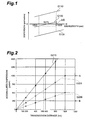
- a dispersion in the center wavelength 1575 nm of the wavelength band of 1530 to 1620 nm is 0, and a difference between the maximum value and the minimum value of the dispersion in the wavelength band of 1530 to 1620 nm is ⁇ D.
- a graph G110 indicates the dispersion of the first optical fiber
- a graph G120 indicates the dispersion of the second optical fiber
- a graph G130 indicates the dispersion (obtained by the fiber length and dispersion value of each of the first and second optical fibers) of the optical transmission line including the first and second optical fibers.
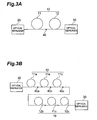
- Fig. 2 is a graph showing the relation between transmission distance and accumulated dispersion with respect to the optical transmission line having the foregoing structure.
- G210 indicates the relation between the transmission distance and the accumulated dispersion value in the case where the difference ⁇ D is 3.6 ps/nm/km
- G220 indicates the relation in the case where the difference ⁇ D is 2.0 ps/nm/km
- G230 indicates the relation in the case where the difference ⁇ D is 1.0 ps/nm/km.
- Fig. 2 is a graph showing the relation between transmission distance and accumulated dispersion with respect to the optical transmission line having the foregoing structure.
- G210 indicates the relation between the transmission distance and the accumulated dispersion value in the case where the difference ⁇ D is 3.6 ps/nm/km
- G220 indicates the relation in the case where the difference ⁇ D is 2.0 ps/nm/km
- G230 indicates the relation in the case where the difference ⁇ D is 1.0 ps/n
- the dispersion slope in the wavelength band of 1530 to 1620 nm is 0.04 ps/nm 2 /km, and the difference ⁇ D between the maximum value and the minimum value of the dispersion in this wavelength band is 3.6 ps/nm/km.
- the optical signals of a bit rate of 10 Gb/s can be transmitted only over a distance of about 550 km, and the optical signals of a bit rate of 20 Gb/s can be transmitted only over a distance of about 150 km.
- the optical signals of a bit rate of 10 Gb/s can be transmitted over a distance of about 1000 km, and the optical signals of a bit rate of 20 Gb/s can be transmitted over a distance of about 250 km.
- the difference ⁇ D is 1.0 ps/nm/km
- the optical signals of a bit rate of 10 Gb/s can be transmitted over a distance of about 2000 km
- the optical signals of a bit rate of 20 Gb/s can be transmitted over a distance of about 500 km.
- the present invention has been made to solve the foregoing problems, and has an object to provide an optical fiber having a structure suitable for long-haul transmission of a plurality of optical signals having wavelengths different from each other in a wavelength band of 1530 to 1620 nm, and an optical transmission line including the same.
- An optical transmission line of the present invention is an optical fiber transmission line disposed in at least one of places between an optical transmitter and an optical receiver, between an optical transmitter and an optical repeater including an optical amplifier, between optical repeaters, and between an optical repeater and an optical receiving station.
- the optical transmission line of the present invention includes one or more first optical fibers, and one or more second optical fibers.
- the optical transmission line may be constituted by one first optical fiber and one second optical fiber, and in the case where a plurality of first optical fibers and a plurality of second optical fibers are mutually fused and connected, the order of connection of these optical fibers may be arbitrary.
- Each of the first optical fibers has a dispersion of +1.0 to +8.0 ps/nm/km in a wavelength band of 1530 to 1620 nm, and a difference between the maximum value and the minimum value of the dispersion is 3.0 ps/nm/km or less, preferably 2.0 ps/nm/km or less.
- each of the second optical fibers has a dispersion of -1.0 to -8.0 ps/nm/km in the above wavelength band, and a difference between the maximum value and the minimum value of the dispersion is 3.0 ps/nm/km or less, preferably 2.0 ps/nm/km or less.
- the optical transmission line is characterized in that in the above wavelength band, an average dispersion value obtained from each fiber length and each dispersion value of the first and second optical fibers is 2.0 ps/nm/km or less, preferably 1.0 ps/nm/km or less, more preferably 0.5 ps/nm/km or less.
- the dispersion (average dispersion value) of the whole optical transmission line of the present invention has opposite signs at the wavelength of 1530 nm and the wavelength of 1620 nm.
- the absolute value of the average dispersion value is 1.0 ps/nm/km or less, and preferably 0.5 ps/nm/km or less.
- the optical transmission line having the structure as described above in the wavelength band of 1530 to 1620 nm, when the difference ⁇ D between the maximum value and the minimum value of the average dispersion value in the whole transmission line is 2.0 ps/nm/km or less (in the case where the average dispersion value becomes 0 at any one of the wavelength band, when the absolute value of the average dispersion value is 1.0 ps/nm/km or less), the optical signals of a bit rate of 10 Gb/s can be transmitted over a distance of about 1000 km, and the optical signals of a bit rate of 20 Gb/s can be transmitted over a distance of about 250 km.
- the optical signals of a bit rate of 10 Gb/s can be transmitted over a distance of about 2000 km, and the optical signals of a bit rate of 20 Gb/s can be transmitted over a distance of about 500 km.
- each of the first and second optical fibers has an effective area of 40 ⁇ m 2 or more at a wavelength of 1550 nm.
- the light intensity per unit sectional area becomes low, the occurrence of a nonlinear optical phenomenon such as four-wave mixing is suppressed.
- the effective area A eff can be given by the following expression (1) as indicated in Japanese Patent Unexamined Publication No. Hei. 8-248251 (EP 0 724 171 A2).
- E is an electric field of transmission light
- r is a distance from the center of a core in the direction of a radius.
- each of the first and second optical fibers has a bending loss of 0.5 dB or less at a wavelength of 1620 nm when it is wound one turn at a diameter of 32 mm.
- the bending loss can be made sufficiently low, and an increase in transmission loss due to formation of a cable or the like can be effectively suppressed.
- An aspect of an optical fiber which can be applied to the optical transmission line having the structure as described above may be an optical fiber in which in the wavelength band of 1530 to 1620 nm, an absolute value of its dispersion is 1.0 to 8.0 ps/nm/km and a difference between a maximum value and a minimum value of the dispersion is 3.0 ps/nm/km or less, preferably 2.0 ps/nm/km or less, and its bending loss is 0.5 dB or less at a wavelength of 1620 nm when it is wound one turn at a diameter of 32 mm.
- the optical fiber of this aspect also has an effective area of 40 ⁇ m 2 or more at a wavelength of 1550 nm.
- another aspect may be an optical fiber in which in the wavelength band of 1530 to 1620 nm, an absolute value of its dispersion is 1.0 to 8.0 ps/nm/km and a difference between a maximum value and a minimum value of the dispersion is 3.0 ps/nm/km or less, preferably 2.0 ps/nm/km or less, and its effective area is less than 60 ⁇ m 2 at a wavelength of 1550 nm.
- this optical fiber of the other aspect has an effective area of 40 ⁇ m 2 or more at the wavelength of 1550 nm.
- the optical fiber of the respective aspects has a structure in which a first core, a second core, a third core, an inner cladding, and an outer cladding are sequentially provided, while an optical axis is made the center.
- the first core extends along a predetermined axis.
- the second core is provided so as to surround the first core and has a refractive index lower than that of the first core.
- the third core is provided so as to surround the second core and has a refractive index higher than that of the second core.
- the inner cladding is provided so as to surround the third core and has a refractive index lower than that of the third core.
- the outer cladding is provided so as to surround the inner cladding and has a refractive index higher than that of the inner cladding.
- a unitary optical fiber with no connection point including first and second portions having core diameters different from each other by 2 % or more can be applied.
- this optical fiber is characterized in that the first portion has a dispersion of +1.0 to +8.0 ps/nm/km in the wavelength band of 1530 to 1620 nm, and a difference between a maximum value and a minimum value of the dispersion is 3.0 ps/nm/km or less, preferably 2.0 ps/nm/km or less, and the second portion includes a dispersion of -1.0 to -8.0 ps/nm/km in the wavelength band, and a difference between a maximum value and a minimum value of the dispersion is 3.0 ps/nm/km or less, preferably 2.0 ps/nm/km or less.
- the optical fiber in which the core diameter is changed along the longitudinal direction like this is obtained by changing wire drawing tension at the time of manufacture, by changing an outer diameter of a core portion in an optical fiber parent material along the longitudinal direction, or the like. Since this optical fiber is a unitary optical fiber (dispersion-managed optical fiber) subjected to dispersion-managed, when a plurality of dispersion-managed optical fibers are fused and connected to each other and an optical transmission line is constituted, it is not necessary to consider the dispersion of each of the optical fibers, and it is possible to easily constitute an optical transmission line which enables long-haul transmission of optical signals having a plurality of wavelengths in the wavelength band of 1530 to 1620 nm. Incidentally, it is preferable that this dispersion-managed optical fiber also has the structure as described above.
- optical transmission line constituted by one dispersion-managed optical fiber as described above or in the optical transmission line in which the plurality of dispersion-managed optical fibers are fused and connected, it is characterized in that a difference between a maximum value and a minimum value of an average dispersion value in a wavelength band of 1530 to 1620 nm is 2.0 ps/nm/km or less, preferably 1.0 ps/nm/km or less.
- optical signals of a bit rate of 10 Gb/s can be transmitted over a distance of about 1000 km, and optical signals of a bit rate of 20 Gb/s can be transmitted over a distance of about 250 km.
- optical signals of a bit rate of 10 Gb/s can be transmitted over a distance of about 2000 km, and optical signals of a bit rate of 20 Gb/s can be transmitted over a distance of about 500 km.
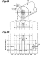
- FIGs. 3A and 3b are views showing a schematic structure of an optical communication system including an optical transmission line of the first embodiment, and as is understood from these drawings, an optical transmission line 10 of the first embodiment is an optical fiber transmission line disposed between optical repeaters 20 and 30.
- the optical repeaters 20 and 30 shown in the drawings may be any of an optical transmitter, a relay including an optical amplifier, and an optical transmitter.
- the optical transmission line 10 can be disposed at any of places between the optical transmitter and the optical receiver, between the optical transmitter and the optical repeater, between the respective optical repeaters, and between the optical repeater and the optical receiver.
- the optical transmission line 10 of the first embodiment is disposed between the respective optical repeaters 20 and 30, and is constituted by a fused and connected first optical fiber 11 and a second optical fiber 12.
- the optical repeater 20 is an optical transmitter
- the optical repeater 20 outputs WDM signals (including a plurality of optical signals) of a wavelength band of 1530 to 1620 nm to the first optical fiber 11.
- the optical transmission line 10 transmits the WDM signals outputted from the optical repeater 20.
- the optical repeater 30 is an optical receiver, the optical repeater 30 receives the WDM signals transmitted through the optical transmission line 10.
- the first optical fiber 11 has a dispersion of +1.0 to +8.0 ps/nm/km in the wavelength band of 1530 to 1620 nm, and a difference between a maximum value and a minimum value of the dispersion is 3.0 ps/nm/km or less, preferably 2.0 ps/nm/km or less.
- the second optical fiber 12 has a dispersion of -1.0 to -8.0 ps/nm/km in the wavelength band of 1530 to 1620 nm, and a difference between a maximum value and a minimum value of the dispersion is 3.0 ps/nm/km or less, preferably 2.0 ps/nm/km or less.
- Each of the first optical fiber 11 and the second optical fiber 12 having the above optical characteristics does not have a zero-dispersion wavelength of 1530 to 1620 nm, it is possible to effectively suppress the occurrence of four-wave mixing.
- a difference ⁇ D between a maximum value and a minimum value of a dispersion of the whole optical transmission line 10, that is, an average dispersion value obtained from each fiber length and each dispersion value of the first and second optical fibers 11 and 12 is 2.0 ps/nm/km or less, preferably 1.0 ps/nm/km, more preferably 0.5 ps/nm/km or less.
- the average dispersion value of the optical transmission line 10 has opposite signs at the wavelength of 1530 nm and the wavelength of 1620 nm.
- the average dispersion value of the optical transmission line 10 becomes 0 at any one (ideally, near the center wavelength of the wavelength band) of the above wavelength band, it is preferable that the absolute value of the average dispersion value is 1.0 ps/nm/km or less, preferably 0.5 ps/nm/km or less.
- the average dispersion value of the optical transmission line 10 is a value given by a weighted average value in view of the fiber length of each of the first optical fiber 11 and the second optical fiber 12, and means the dispersion value of the whole optical transmission line 10.
- the optical transmission line 10 since the difference ⁇ D between the maximum value and the minimum value of the dispersion (average dispersion value) in the wavelength band of 1530 to 1620 nm is sufficiently small, it is possible to effectively suppress the deterioration of the waveform of the optical signal due to the dispersion. That is, in the wavelength band of 1530 to 1620 nm, when the difference ⁇ D between the maximum value and the minimum value of the dispersion value is 2.0 ps/nm/km or less, the optical transmission line 10 can transmit the optical signal of a bit rate of 10 Gb/s over a distance of about 1000 km, and can transmit the optical signal of a bit rate of 20 Gb/s over a distance of about 250 km (see Fig. 2).
- the difference ⁇ D between the maximum value and the minimum value of the average dispersion value of the optical transmission line 10 is 1.0 ps/nm/km or less, it can transmit the optical signal of a bit rate of 10 Gb/s over a distance of about 2000 km, and can transmit the optical signal of a bit rate of 20 Gb/s over a distance of about 500 km.
- the optical transmission line 10 may include a structure in which a plurality of first optical fibers and a plurality of second optical fibers 12 are fused and connected, and the order of connection of these optical fibers is also arbitrary.
- Fig. 3B shows an example in which the optical transmission line of the first embodiment is constituted like this by a plurality of first optical fibers 11a to 11c and a plurality of second optical fibers 12a to 12c.
- each of the first optical fiber 11 and the second optical fiber 12 has an effective area A eff of 40 ⁇ m 2 or more at a wavelength of 1550 nm.
- the size of this effective area is equal to or larger than the effective area of a normal dispersion-shifted optical fiber having a zero-dispersion wavelength near the wavelength of 1550 nm, and the light intensity per unit sectional area becomes low, so that the occurrence of a nonlinear optical phenomenon such as four-wave mixing can be effectively suppressed.
- the power of an optical signal transmitted through the optical transmission line 10 can be made high, and a transmission distance can be made long.
- each of the first optical fiber 11 and the second optical fiber 12 has a bending loss of 0.5 dB or less when it is wound one turn at a diameter of 32 mm.
- the bending loss becomes large as the wavelength becomes long, the bending loss can be sufficiently suppressed in the wavelength band of 1530 to 1620 nm by regulating the bending loss at the side of the longest wavelength of the wavelength band, and it is possible to suppress an increase in transmission loss due to formation of a cable or the like.
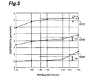
- Figs. 4A and 4B are views showing a sectional structure common to the first optical fiber 11 and the second optical fiber and its refractive index profile.
- reference numeral 100 designates an optical fiber corresponding to the first and second optical fibers 11 and 12.
- the optical fiber 100 includes a core region 110 extending along a predetermined axis, and a cladding region 120 provided so as to surround the outer periphery of the core region 110.
- the core region 110 includes a first core 111 having a refractive index n1, a second core 112 provided so as to surround the outer periphery of the first core 111 and having a refractive index n2 ( ⁇ n1), and a third core 113 provided so as to surround the outer periphery of the second core 112 and having a refractive index n3 (> n2).
- the cladding region 120 includes an inner cladding 121 provided so as to surround the outer periphery of the third core 113 and having a refractive index n4 ( ⁇ n3) and an outer cladding 122 provided so as to surround the outer periphery of the inner cladding 121 and having a refractive index n5 (> n4).
- the relative refractive index differences given by the above respective expressions are indicated by the percentage, and the order of parameters in the respective expressions is arbitrary.
- the relative refractive index difference of a region having a refractive index lower than that of the outer cladding 122 as the reference region is indicated by a negative value.
- the refractive index profile shown in Fig. 3B indicates the relation between each portion on a line L of the optical fiber 100 shown in Fig. 3A and its refractive index, and in this refractive index profile 150, a region 151 indicates a refractive index of each portion of the first core 111 on the line L, a region 152 indicates a refractive index of each portion of the second core 112 on the line L, a region 153 indicates a refractive index of each portion of the third core 113 on the line L, a region 154 indicates a refractive index of each portion of the inner cladding 121 on the line L, and a region 155 indicates a refractive index of each portion of the outer cladding 122 on the line L.
- a first optical fiber of this first applicative example has the sectional structure shown in Fig. 4A, and specifically, an outer diameter 2a of the first core 111 is 6.0 ⁇ m, an outer diameter 2b of the second core 112 is 17.5 ⁇ m, an outer diameter 2c of the third core 113 is 25.0 ⁇ m, and an outer diameter 2d of the inner cladding 121 is 50.0 ⁇ m.
- the relative refractive index difference ⁇ n1 of the first core 111 is 0.50 %
- the relative refractive index difference ⁇ n2 of the second core 112 is -0.15%
- the relative refractive index difference ⁇ n3 of the third core 113 is 0.27%
- the relative refractive index difference ⁇ n4 of the inner cladding 121 is -0.15%.
- the optical fiber like this can be obtained by using silica as a base, by adding, for example, Ge elements into the first core 111 and the third core 113, and by adding F elements into the second core 112 and the inner cladding 121.
- the dispersion at the wavelength of 1530 nm is 3.06 ps/nm/km
- the dispersion at the wavelength of 1550 ⁇ m is 3.15 ps/nm/km
- the dispersion at the wavelength of 1620 ⁇ m is 3.20 ps/nm/km.
- the difference ⁇ D between the maximum value and the minimum value of the dispersion in the wavelength band of 1530 to 1620 nm is 0.14 ps/nm/km.
- the effective area is 47.4 ⁇ m 2
- a mode field diameter is 7.80 ⁇ m.
- a cut-off wavelength (cut-off wavelength of an LP11-mode in the state where an optical fiber of a length of 2 m is wound only one turn at a radius of 140 mm) is 1.56 ⁇ m.
- a second optical fiber of the first applicative example has also the sectional structure shown in Fig. 4A, and specifically, the outer diameter 2a of the first core 111 is 5.7 ( ⁇ m, the outer diameter 2b of the second core 112 is 16.7 ⁇ m, the outer diameter 2c of the third core 113 is 23.8 ⁇ m, and the outer diameter 2d of the inner cladding 121 is 47.6 ⁇ m.
- the relative refractive index difference ⁇ n1 of the first core 111 is 0.50 %
- the relative refractive index difference ⁇ n2 of the second core 112 is -0.15%
- the relative refractive index difference ⁇ n3 of the third core 113 is 0.27%
- the relative refractive index difference ⁇ n4 of the inner cladding 121 is -0.15%.
- the optical fiber like this can be obtained by using silica as a base, by adding, for example, Ge elements into the first core 111 and the third core 113, and by adding F elements into the second core 112 and the inner cladding 121.
- the dispersion at the wavelength of 1530 nm is -3.02 ps/nm/km
- the dispersion at the wavelength of 1550 ⁇ m is -3.04 ps/nm/km
- the dispersion at the wavelength of 1620 ⁇ m is -2.44 ps/nm/km.
- the difference ⁇ D between the maximum value and the minimum value of the dispersion in the wavelength band of 1530 to 1620 nm is 0.60 ps/nm/km.
- the effective area is 50.3 ⁇ m 2
- the mode field diameter is 8.00 ⁇ m.
- the bending loss at the wavelength of 1550 nm is 1.2 dB/turn
- the bending loss at the wavelength of 1620 nm is 5.7 dB/turn.
- the cut-off wavelength is 1.44 ⁇ m.
- Fig. 5 is a graph showing dispersion characteristics of the whole optical transmission line of the first applicative example and dispersion characteristics of each of the first and second optical fibers.
- a graph G510 in the drawing indicates the dispersion characteristics of the first optical fiber of the first applicative example in the wavelength band of 1530 to 1620 nm
- a graph G520 indicates the dispersion characteristics of the second optical fiber of the first applicative example in the wavelength band of 1530 to 1620 nm
- a graph G530 indicates the dispersion characteristics of the whole optical transmission line of the first applicative example in the wavelength band of 1530 to 1620 nm.
- fiber lengths of the first and second optical fibers are equal to each other, and in the whole optical transmission line of the first applicative example, the difference ⁇ D between the maximum value and the minimum value of the dispersion is about 0.5 ps/nm/km in the wavelength band of 1530 to 1620 nm.
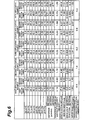
- Fig. 6 is a table showing structural parameters and optical characteristics of a first optical fiber and a second optical fiber as respective structural elements of second to fifth applicative examples together with the foregoing first applicative example.
- a first optical fiber applied to an optical transmission line of a second applicative example has also the sectional structure shown in Fig. 4A, and specifically, the outer diameter 2a of the first core 111 is 6.2 ⁇ m, the outer diameter 2b of the second core 112 is 16.7 ⁇ m, the outer diameter 2c of the third core 113 is 24.6 ⁇ m, and the outer diameter 2d of the inner cladding 121 is 49.2 ⁇ m.
- the relative refractive index difference ⁇ n1 of the first core 111 is 0.55 %
- the relative refractive index difference ⁇ n2 of the second core 112 is -0.15%
- the relative refractive index difference ⁇ n3 of the third core 113 is 0.27%
- the relative refractive index difference ⁇ n4 of the inner cladding 121 is -0.15%.
- the dispersion at the wavelength of 1530 nm is 6.52 ps/nm/km
- the dispersion at the wavelength of 1550 ⁇ m is 6.86 ps/nm/km
- the dispersion at the wavelength of 1620 ⁇ m is 7.62 ps/nm/km.
- the difference ⁇ D between the maximum value and the minimum value of the dispersion in the wavelength band of 1530 to 1620 nm is 1.10 ps/nm/km.
- the effective area is 44.0 ⁇ m 2
- the mode field diameter is 7.79 ( ⁇ m.
- a cut-off wavelength (cut-off wavelength of an LP11-mode in the state where an optical fiber of a length of 2 m is wound only one turn at a radius of 140 mm) is 1.69 ⁇ m.
- a second optical fiber applied to the optical transmission line of the second applicative example has also the sectional structure shown in Fig. 4A, and specifically, the outer diameter 2a of the first core 111 is 5.6 ⁇ m, the outer diameter 2b of the second core 112 is 14.7 ⁇ m, the outer diameter 2c of the third core 113 is 22.3 ⁇ m, and the outer diameter 2d of the inner cladding 121 is 44.6 ⁇ m.
- the relative refractive index difference ⁇ n1 of the first core 111 is 0.57 %
- the relative refractive index difference ⁇ n2 of the second core 112 is -0.15%
- the relative refractive index difference ⁇ n3 of the third core 113 is 0.30%
- the relative refractive index difference ⁇ n4 of the inner cladding 121 is -0.15%.
- the dispersion at the wavelength of 1530 nm is -6.89 ps/nm/km
- the dispersion at the wavelength of 1550 ⁇ m is -6.78 ps/nm/km
- the dispersion at the wavelength of 1620 ⁇ m is -5.14 ps/nm/km.
- the difference ⁇ D between the maximum value and the minimum value of the dispersion in the wavelength band of 1530 to 1620 nm is 1.75 ps/nm/km.
- the effective area is 48.6 ⁇ m 2
- the mode field diameter is 7.76 ⁇ m.
- the bending loss at the wavelength of 1550 nm is 0.02 dB/turn
- the bending loss at the wavelength of 1620 nm is 0.2 dB/turn.
- the cut-off wavelength is 1.70 ⁇ m.
- Fig. 7 is a graph showing dispersion characteristics of the whole optical transmission line of the second applicative example and the dispersion characteristics of each of the first and second optical fibers.
- a graph G710 in the drawing indicates the dispersion characteristics of the first optical fiber of the second applicative example in the wavelength band of 1530 to 1620 nm
- a graph G720 indicates the dispersion characteristics of the second optical fiber of the second applicative example in the wavelength band of 1530 to 1620 nm
- a graph G730 indicates the dispersion characteristics of the whole optical transmission line of the second applicative example in the wavelength band of 1530 to 1620 nm.
- fiber lengths of the first and second optical fibers are equal to each other, and in the whole optical transmission line of the second applicative example, the difference ⁇ D between the maximum value and the minimum value of the dispersion is about 1.4 ps/nm/km in the wavelength band of 1530 to 1620 nm.
- a first optical fiber applied to an optical transmission line of a third applicative example has also the sectional structure shown in Fig. 4A, and specifically, the outer diameter 2a of the first core 111 is 6.3, the outer diameter 2b of the second core 112 is 16.6 ⁇ m, the outer diameter 2c of the third core 113 is 25.2 ⁇ m, and the outer diameter 2d of the inner cladding 121 is 50.4 ⁇ m.
- the relative refractive index difference ⁇ n1 of the first core 111 is 0.53 %
- the relative refractive index difference ⁇ n2 of the second core 112 is -0.15%
- the relative refractive index difference ⁇ n3 of the third core 113 is 0.30%
- the relative refractive index difference ⁇ n4 of the inner cladding 121 is -0.15%.
- the dispersion at the wavelength of 1530 nm is 3.81 ps/nm/km
- the dispersion at the wavelength of 1550 ⁇ m is 3.82 ps/nm/km
- the dispersion at the wavelength of 1620 ⁇ m is 3.58 ps/nm/km.
- the difference ⁇ D between the maximum value and the minimum value of the dispersion in the wavelength band of 1530 to 1620 nm is 0.23 ps/nm/km.
- the effective area is 47.8 ⁇ m 2
- the mode field diameter is 7.77 ⁇ m.
- a cut-off wavelength (cut-off wavelength of an LP11-mode in the state where an optical fiber of a length 2 m is wound only one turn at a radius of 140 mm) is 1.91 ⁇ m.
- a second optical fiber applied to the optical transmission line of the third applicative example has also the sectional structure shown in Fig. 4A, and specifically, the outer diameter 2a of the first core 111 is 6.0 ⁇ m, the outer diameter 2b of the second core 112 is 15.7 ⁇ m, the outer diameter 2c of the third core 113 is 23.8 ⁇ m, and the outer diameter 2d of the inner cladding 121 is 47.6 ⁇ m.
- the relative refractive index difference ⁇ n1 of the first core 111 is 0.53 %
- the relative refractive index difference ⁇ n2 of the second core 112 is -0.15%
- the relative refractive index difference ⁇ n3 of the third core 113 is 0.30%
- the relative refractive index difference ⁇ n4 of the inner cladding 121 is -0.15%.
- the dispersion at the wavelength of 1530 nm is -3.68 ps/nm/km
- the dispersion at the wavelength of 1550 ⁇ m is -3.75 ps/nm/km
- the dispersion at the wavelength of 1620 ⁇ m is -3.02 ps/nm/km.
- the difference ⁇ D between the maximum value and the minimum value of the dispersion in the wavelength band of 1530 to 1620 nm is 0.73 ps/nm/km.
- the effective area is 51.3 ⁇ m 2
- the mode field diameter is 7.95 ⁇ m.
- the bending loss at the wavelength of 1550 nm is 0.04 dB/turn
- the bending loss at the wavelength of 1620 nm is 0.3 dB/turn.
- the cut-off wavelength is 1.80 ⁇ m.
- Fig. 8 is a graph showing dispersion characteristics of the whole optical transmission line of the third applicative example and dispersion characteristics of each of the first and second optical fibers.
- a graph G810 in the drawing indicates the dispersion characteristics of the first optical fiber of the third applicative example in the wavelength band of 1530 to 1620 nm
- a graph G820 indicates the dispersion characteristics of the second optical fiber of the third applicative example in the wavelength band of 1530 to 1620 nm
- a graph G830 indicates the dispersion characteristics of the whole optical transmission line of the third applicative example in the wavelength band of 1530 to 1620 nm.
- fiber lengths of the first and second optical fibers are equal to each other, and in the whole optical transmission line of the third applicative example, the difference ⁇ D between the maximum value and the minimum value of the dispersion is about 0.2 ps/nm/km in the wavelength band of 1530 to 1620 nm.
- a first optical fiber applied to an optical transmission line of a fourth applicative example has also the sectional structure shown in Fig. 4A, and specifically, the outer diameter 2a of the first core 111 is 6.9, the outer diameter 2b of the second core 112 is 17.6 ⁇ m, the outer diameter 2c of the third core 113 is 26.6 ⁇ m, and the outer diameter 2d of the inner cladding 121 is 53.2 ⁇ m.
- the relative refractive index difference ⁇ n1 of the first core 111 is 0.49 %
- the relative refractive index difference ⁇ n2 of the second core 112 is -0.15%
- the relative refractive index difference ⁇ n3 of the third core 113 is 0.32%
- the relative refractive index difference ⁇ n4 of the inner cladding 121 is -0.15%.
- the dispersion at the wavelength of 1530 nm is 3.50 ps/nm/km
- the dispersion at the wavelength of 1550 ⁇ m is 3.34 ps/nm/km
- the dispersion at the wavelength of 1620 ⁇ m is 3.00 ps/nm/km.
- the difference ⁇ D between the maximum value and the minimum value of the dispersion in the wavelength band of 1530 to 1620 nm is 0.50 ps/nm/km.
- the effective area is 56.5 ⁇ m 2
- the mode field diameter is 8.29 ⁇ m.
- a cut-off wavelength (cut-off wavelength of an LP11-mode in the state where an optical fiber of a length 2 m is wound only one turn at a radius of 140 mm) is 2.19 ⁇ m.
- a second optical fiber applied to the optical transmission line of the fourth applicative example has also the sectional structure shown in Fig. 4A, and specifically, the outer diameter 2a of the first core 111 is 6.6 ⁇ m, the outer diameter 2b of the second core 112 is 16.7 ⁇ m, the outer diameter 2c of the third core 113 is 25.3 ⁇ m, and the outer diameter 2d of the inner cladding 121 is 50.6 ⁇ m.
- the relative refractive index difference ⁇ n1 of the first core 111 is 0.49 %
- the relative refractive index difference ⁇ n2 of the second core 112 is -0.15%
- the relative refractive index difference ⁇ n3 of the third core 113 is 0.32%
- the relative refractive index difference ⁇ n4 of the inner cladding 121 is -0.15%.
- the dispersion at the wavelength of 1530 nm is -3.36 ps/nm/km
- the dispersion at the wavelength of 1550 ⁇ m is -3.33 ps/nm/km
- the dispersion at the wavelength of 1620 ⁇ m is -1.39 ps/nm/km.
- the difference ⁇ D between the maximum value and the minimum value of the dispersion in wavelength band of 1530 to 1620 nm is 1.94 ps/nm/km.
- the effective area is 62.7 ⁇ m 2
- the mode field diameter is 8.51 ⁇ m.
- the bending loss at the wavelength of 1550 nm is 0.02 dB/turn
- the bending loss at the wavelength of 1620 nm is 0.1 dB/turn.
- the cut-off wavelength is 2.07 ⁇ m.
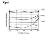
- Fig. 9 is a graph showing dispersion characteristics of the whole optical transmission line of the fourth applicative example and dispersion characteristics of each of the first and second optical fibers.
- a graph G910 in the drawing indicates the dispersion characteristics of the first optical fiber of the fourth applicative example in the wavelength band of 1530 to 1620 nm
- a graph G920 indicates the dispersion characteristics of the second optical fiber of the fourth applicative example in the wavelength band of 1530 to 1620 nm
- a graph G930 indicates the dispersion characteristics of the whole optical transmission line of the fourth applicative example in the wavelength band of 1530 to 1620 nm.
- fiber lengths of the first and second optical fibers are equal to each other, and in the whole optical transmission line of the fourth applicative example, the difference ⁇ D between the maximum value and the minimum value of the dispersion is about 0.8 ps/nm/km in the wavelength band of 1530 to 1620 nm.
- a first optical fiber applied to an optical transmission line of a fifth applicative example has also the sectional structure shown in Fig. 4A, and specifically, the outer diameter 2a of the first core 111 is 6.1, the outer diameter 2b of the second core 112 is 15.1 ⁇ m, the outer diameter 2c of the third core 113 is 24.3 ⁇ m, and the outer diameter 2d of the inner cladding 121 is 48.6 ⁇ m.
- the relative refractive index difference ⁇ n1 of the first core 111 is 0.58 %
- the relative refractive index difference ⁇ n2 of the second core 112 is -0.18%
- the relative refractive index difference ⁇ n3 of the third core 113 is 0.25%
- the relative refractive index difference ⁇ n4 of the inner cladding 121 is -0.18%.
- the dispersion at the wavelength of 1530 nm is 5.71 ps/nm/km
- the dispersion at the wavelength of 1550 ⁇ m is 5.96 ps/nm/km
- the dispersion at the wavelength of 1620 ⁇ m is 6.44 ps/nm/km.
- the difference ⁇ D between the maximum value and the minimum value of the dispersion in the wavelength band of 1530 to 1620 nm is 0.73 ps/nm/km.
- the effective area is 41.6 ⁇ m 2 and the mode field diameter is 7.30 ⁇ m.
- a cut-off wavelength (cut-off wavelength of an LP11-mode in the state where an optical fiber of a length of 2 m is wound only one turn at a radius of 140 mm) is 1.69 ⁇ m.
- a second optical fiber applied to the optical transmission line of the fifth applicative example has also the sectional structure shown in Fig. 4A, and specifically, the outer diameter 2a of the first core 111 is 5.5 ⁇ m, the outer diameter 2b of the second core 112 is 13.6 ⁇ m, the outer diameter 2c of the third core 113 is 22.0 ⁇ m, and the outer diameter 2d of the inner cladding 121 is 44.0 ⁇ m.
- the relative refractive index difference ⁇ n1 of the first core 111 is 0.58 %
- the relative refractive index difference ⁇ n2 of the second core 112 is -0.18%
- the relative refractive index difference ⁇ n3 of the third core 113 is 0.25%
- the relative refractive index difference ⁇ n4 of the inner cladding 121 is -0.18%.
- the dispersion at the wavelength of 1530 nm is -6.00 ps/nm/km
- the dispersion at the wavelength of 1550 ⁇ m is -5.91 ps/nm/km
- the dispersion at the wavelength of 1620 ⁇ m is -4.71 ps/nm/km.
- the difference ⁇ D between the maximum value and the minimum value of the dispersion in the wavelength band of 1530 to 1620 nm is 1.29 ps/nm/km.
- the effective area is 44.8 ⁇ m 2
- the mode field diameter is 7.51 ⁇ m.
- the bending loss at the wavelength of 1550 nm is 0.04 dB/turn
- the bending loss at the wavelength of 1620 nm is 0.3 dB/turn.
- the cut-off wavelength is 1.53 ⁇ m.
- Fig. 10 is a graph showing dispersion characteristics of the whole optical transmission line of the fifth applicative example and dispersion characteristics of each of the first and second optical fibers.
- a graph G1010 in the drawing indicates the dispersion characteristics of the first optical fiber of the fifth applicative example in the wavelength band of 1530 to 1620 nm
- a graph G1020 indicates the dispersion characteristics of the second optical fiber of the fifth applicative example in the wavelength band of 1530 to 1620 nm
- a graph G1030 indicates the dispersion characteristics of the whole optical transmission line of the fifth applicative example in the wavelength band of 1530 to 1620 nm.
- fiber lengths of the first and second optical fibers are equal to each other, and in the whole optical transmission line of the fifth applicative example, the difference ⁇ D between the maximum value and the minimum value of the dispersion is about 1.0 ps/nm/km in the wavelength band of 1530 to 1620 nm.
- an optical fiber in the wavelength band of 1530 to 1620 nm, may have a dispersion in which its absolute value is 1.0 to 8.0 ps/nm/km and a difference between its maximum value and its minimum value is 3.0 ps/nm/km or less, preferably 2.0 ps/nm/km or less, and have a bending loss of 0.5 dB or less at the wavelength of 1620 nm when it is wound one turn at a diameter of 32 mm.
- the optical fiber of this aspect has also an effective area of 40 ⁇ m 2 or more at the wavelength of 1550 nm.
- an optical fiber may have a dispersion in which its absolute value is 1.0 to 8.0 ps/nm/km and a difference between its maximum value and its minimum value is 3.0 ps/nm/km or less, preferably 2.0 ps/nm/km or less, and have an effective area of less than 60 ⁇ m 2 at the wavelength of 1550 nm.
- the optical fiber of this aspect has an effective area of 40 ⁇ m 2 or more at the wavelength of 1550 nm.
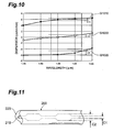
- FIG. 11 is a view for explaining the structure of an optical fiber applicable to the optical transmission line of the second embodiment.
- An optical fiber 200 includes a core region 210 extending along a predetermined axis and a cladding region 220 provided so as to surround the outer periphery of the core region 210, and has the sectional structure and the refractive index profile shown in Figs. 4A and 4B.
- this optical fiber 200 is a unitary optical fiber characterized in that the outer diameter of the core region 210 is changed along the longitudinal direction, and specifically, core diameters are different from each other by 2 % or more between an outer diameter c2 of a portion having a relatively small core diameter and an outer diameter c2 of a portion having a relatively large core diameter.
- Figs. 12A and 12B are views showing the structure and dispersion characteristics of an optical fiber applicable to a first applicative example of the optical transmission line of this second embodiment.
- An optical fiber 40 of this first applicative example is a unitary optical fiber including no connection point as shown in Fig. 12B, and includes a portion 42 1 , a portion 41 1 , a portion 42 2 , a portion 41 2 , a portion 42 3 , a portion 41 3 , ... sequentially from one end portion.
- an outer diameter of the portion 41 n and an outer diameter of the portion 42 n are different from each other by 2 % or more. Since the dispersion of each of the portions 41 n and 42 n in the wavelength band of 1530 to 1620 nm is not zero, this optical fiber 40 can effectively suppress the occurrence of four-wave mixing.
- the relative refractive index difference ⁇ n1 of the first core 111 is 0.50 %
- the relative refractive index difference ⁇ n2 of the second core 112 is -0.15%
- the relative refractive index difference ⁇ n3 of the third core 113 is 0.27%
- the relative refractive index difference ⁇ n4 of the inner cladding 121 is -0.15%.
- the length of each of the portions 41 n and 42 n is made 5 km.
- the outer diameter 2c of the third core 113 is made 23.8 ⁇ m under the above condition, a portion having dispersion characteristics (dispersion at the wavelength of 1550 nm is -3.04 ps/nm/km ) similar to the second optical fiber 12 applicable to the optical transmission line of the first embodiment can be designed, and this portion corresponds to the portion 42 n in the optical fiber 40.
- the outer diameter 2c of the third core 113 is increased by 5 % and is made 25.0 ⁇ m, a portion having dispersion characteristics (dispersion at the wavelength of 1550 nm is 3.15 ps/nm/km ) similar to the first optical fiber 11 applicable to the optical transmission line of the first embodiment can be obtained, and this portion corresponds to the portion 41 n of the optical fiber 40.
- the optical fiber 40 of the first applicative example like this can be easily obtained by preparing an optical fiber parent material in which a relative refractive index distribution and an outer diameter of each portion are constant in the longitudinal direction, by adjusting (for example, changing of wire drawing tension) a fiber diameter in the longitudinal direction when this optical fiber parent material is drawn, and the like.
- the above first to third cores 111 to 113 are included in the above core region 210, and the above inner cladding 121 and the outer cladding 122 are included in the above cladding region 220.
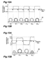
- FIGs. 13A and 13B are views showing the structure and dispersion characteristics of an optical fiber applicable to a second applicative example of the optical transmission line of this second embodiment.
- An optical fiber 50 of this second applicative example is a unitary optical fiber including no connection point as shown in Fig. 13B, and includes a portion 52 1 , a portion 51 1 , a portion 52 2 , a portion 51 2 , ... sequentially from one end portion.
- an outer diameter of the portion 51 n and an outer diameter of the portion 52 n are different from each other by 2 % or more. Since the dispersion of each of the portions 51 n and 52 n in the wavelength band of 1530 to 1620 nm is not zero, this optical fiber 50 can effectively suppress the occurrence of four-wave mixing.
- the optical fiber 50 of this second applicative example is different from the first applicative example in that the respective portions 51 n and 52 n have different values in the length and dispersion. Specifically, it may be set such that the length of the portion 52 1 is 3 km, the length of the portion 51 1 is 5 km, the length of the portion 52 2 is 5 km, and the length of the portion 51 2 is 3 km (the length of each of the portions may not be necessarily constant). Besides, the dispersion of the portion 51 n may not be constant, for example, the dispersion in the portion 51 1 is about 2.2 ps/nm/km, and the dispersion in the portion 51 2 is about 3.4 ps/nm/km.
- the dispersion of the portion 52 n may not be constant, for example, the dispersion in the portion 52 1 is about -2.1 ps/nm/km, and the dispersion in the portion 52 2 is about -3.5 ps/nm/km.
- the change of the dispersion at a boundary between adjacent portions, that is, the change of the fiber structure may not be steep.
- each of the optical fiber 40 (first applicative example) and the optical fiber 50 (second applicative example) applied to the optical transmission line of the second embodiment is the unitary fiber subjected to dispersion-managed.
- the optical transmission line is constituted by fusing and connecting a plurality of optical fibers, it is not necessary to consider the dispersion of each of the optical fibers, and a structure suitable for long-haul transmission of a WDM signal in the wavelength band of 1530 to 1620 nm can be easily obtained.
- the dispersion occurs (dispersion is not zero) in most of the wavelength band of 1530 to 1620 nm, the occurrence of four-wave mixing can be effectively suppressed.
- the optical transmission line of the second embodiment enables the long-haul transmission of the WDM signal in the wavelength band of the wavelength 1530 to 1620 nm.
- a difference ⁇ D between a maximum value and a minimum value of an average dispersion in the wavelength band of 1530 to 1620 nm is 2.0 ps/nm/km or less, preferably 1.0 ps/nm/km or less, more preferably 0.5 ps/nm/km or less.
- an optical signal of a bit rate of 10 Gb/s can be transmitted over a distance of about 1000 km, and an optical signal of a bit rate of 20 Gb/s can be transmitted over a distance of about 250 km.
- an optical signal of a bit rate of 10 Gb/s can be transmitted over a distance of about 2000 km, and an optical signal of a bit rate of 20 Gb/s can be transmitted over a distance of about 500 km.
- the bending loss at the wavelength of 1620 nm is 0.5 dB or less when it is wound one turn at a diameter of 32 mm, and the effective area at the wavelength of 1550 nm is 40 ⁇ m 2 or more.
- the optical fiber applied to the optical transmission line may be one having the foregoing refractive index profile (see Fig. 4B) and different parameters, or having another refractive index profile.
- the number of optical fibers constituting the optical transmission line is arbitrary.
- the optical transmission line of the present invention is constituted by fusing and connecting the first and second optical fibers having different dispersion characteristics in the wavelength band of 1530 to 1620 nm coincident with the amplification wavelength band for optical amplification, or by the unitary optical fiber having the first and second portions with different core diameters so as to intentionally change the dispersion characteristics in the wavelength band.
- the first optical fiber or the first portion has the dispersion of +1.0 to +8.0 ps/nm/km in the wavelength band, and the difference between the maximum value and the minimum value of the diffusion is 3.0 ps/nm/km or less, preferably 2.0 ps/nm/km or less.
- the second optical fiber or the second portion has the dispersion of -1.0 to -8.0 ps/nm/km in the wavelength band, and the difference between the maximum value and the minimum value of the diffusion is 3.0 ps/nm/km or less, preferably 2.0 ps/nm/km or less.
- the difference between the maximum value and the minimum value of the average dispersion value in the wavelength band is 2.0 ps/nm/km or less, preferably 1.0 ps/nm/km or less, more preferably 0.5 ps/nm/km or less.
- the occurrence of four-wave mixing can be effectively suppressed, and waveform deterioration of an optical signal due to the dispersion can also be sufficiently suppressed.
- the wavelength band of 1530 to 1620 nm long-haul transmission of the WDM signal (including optical signals having wavelengths different from each other) becomes possible.
Landscapes
- Physics & Mathematics (AREA)
- Chemical & Material Sciences (AREA)
- Dispersion Chemistry (AREA)
- General Physics & Mathematics (AREA)
- Optics & Photonics (AREA)
- Electromagnetism (AREA)
- Engineering & Computer Science (AREA)
- Computer Networks & Wireless Communication (AREA)
- Signal Processing (AREA)
- Optical Communication System (AREA)
Abstract
Description

Claims (21)
- An optical transmission line, comprising:wherein, in the wavelength band, a difference between a maximum value and a minimum value of an average dispersion value obtained from each fiber length and each dispersion value of said first and second optical fibers is 2.0 ps/nm/km or less.one or more first optical fibers each having a dispersion of +1.0 to +8.0 ps/nm/km in a wavelength band of 1530 to 1620 nm and a difference of 3.0 ps/nm/km or less between a maximum value and a minimum value of the dispersion thereof; andone or more second optical fibers each having a dispersion of -1.0 to -8.0 ps/nm/km in the wavelength band and a difference of 3.0 ps/nm/km or less between a maximum value and a minimum value of the dispersion thereof,
- An optical transmission line according to claim 1, wherein, in each of said first and second optical fibers, the difference between the maximum value and the minimum value of the dispersion thereof in the wavelength band is 2.0 ps/nm/km or less.
- An optical transmission line according to claim 1, wherein, in the wavelength band, the difference between the maximum value and the minimum value of the average dispersion value is 1.0 ps/nm/km or less.
- An optical transmission line according to claim 3, wherein, in the wavelength band, an absolute value of the average dispersion value is 1.0 ps/nm/km or less.
- An optical transmission line according to claim 3, wherein, in the wavelength band, the difference between the maximum value and the minimum value of the average dispersion value is 0.5 ps/nm/km or less.
- An optical transmission line according to claim 5, wherein, in the wavelength band, an absolute value of the average dispersion value obtained from each fiber length and each dispersion value of said first and second optical fibers is 0.5 ps/nm/km or less.
- An optical transmission line according to claim 1, wherein each of said first and second optical fibers has an effective area of 40 µm2 or more at a wavelength of 1550 nm.
- An optical transmission line according to claim 1, wherein each of said first and second optical fibers has a bending loss of 0.5 dB or less at a wavelength of 1620 nm when it is wound one turn at a diameter of 32 mm.
- An optical fiber having:a dispersion having an absolute value of 1.0 to 8.0 ps/nm/km and a difference of 3.0 ps/nm/km or less between a maximum value and a minimum value in a wavelength band of 1530 to 1620 nm; anda bending loss of 0.5 dB or less at a wavelength of 1620 nm when it is wound one turn at a diameter of 32 mm.
- An optical fiber according to claim 9, wherein in the wavelength band, the dispersion has the difference of 2.0 ps/nm/km or less between the maximum value and the minimum value.
- An optical fiber according to claim 9, further comprising an effective area of 40 µm2 or more at a wavelength of 1550 nm.
- An optical fiber comprising:a dispersion having an absolute value of 1.0 to 8.0 ps/nm/km and a difference of 3.0 ps/nm/km or less between a maximum value and a minimum value in a wavelength band of 1530 to 1620 nm; andan effective area of less than 60 µm2 at a wavelength of 1550 nm.
- An optical fiber according to claim 12, wherein in the wavelength band, the dispersion has the difference of 2.0 ps/nm/km or less between the maximum value and the minimum value.
- An optical fiber according to claim 12, wherein the effective area is 40 µm2 or more at the wavelength of 1550 nm.
- A unitary optical fiber with no connection point, comprising first portions and second portions having core diameters different from each other by 2 % or more,wherein each of said first portions has a dispersion of +1.0 to +8.0 ps/nm/km in a wavelength band of 1530 to 1620 nm, and a difference of 3.0 ps/nm/km or less between a maximum value and a minimum value of the dispersion thereof, andwherein said second portions has a dispersion of -1.0 to -8.0 ps/nm/km in the wavelength band, and a difference of 3.0 ps/nm/km or less between a maximum value and a minimum value of the dispersion thereof.
- An optical fiber according to claim 15, wherein, in each of said first and second portions, the difference between the maximum value and the minimum value of the dispersion thereof in the wavelength band is 2.0 ps/nm/km or less.
- An optical fiber according to any one of claims 9 to 16, further comprising:a first core extending along a predetermined axis;a second core provided on an outer periphery of said first core and having a refractive index lower than that of said first core;a third core provided on an outer periphery of said second core and having a refractive index higher than that of said second core;an inner cladding provided on an outer periphery of said third core and having a refractive index lower than that of said third core; andan outer cladding provided on an outer periphery of said inner cladding and having a refractive index higher than that of inner cladding.
- An optical transmission line in which a plurality of optical fibers of claim 15 or 16 are optically connected to each other,
wherein, in a wavelength band of 1530 to 1620 nm, a difference between a maximum value and a minimum value of an average dispersion value obtained from each fiber length and each dispersion value of said plurality of optical fibers is 2.0 ps/nm/km or less. - An optical transmission line according to claim 18, wherein, in the wavelength band, the difference between the maximum value and the minimum value of the average dispersion is 1.0 ps/nm/km or less.
- An optical transmission line according to claim 18, wherein, in the wavelength band, an absolute value of the average dispersion is 1.0 ps/nm/km or less.
- An optical transmission line according to claim 19, wherein, in the wavelength band, the difference between the maximum value and the minimum value of the average dispersion is 0.5 ps/nm/km or less.
Applications Claiming Priority (5)
| Application Number | Priority Date | Filing Date | Title |
|---|---|---|---|
| JP10962799 | 1999-04-16 | ||
| JP10962799 | 1999-04-16 | ||
| JP25918999 | 1999-09-13 | ||
| JP25918999 | 1999-09-13 | ||
| PCT/JP2000/002487 WO2000063732A1 (en) | 1999-04-16 | 2000-04-17 | Optical fiber and optical transmission line comprising the same |
Publications (2)
| Publication Number | Publication Date |
|---|---|
| EP1186919A1 true EP1186919A1 (en) | 2002-03-13 |
| EP1186919A4 EP1186919A4 (en) | 2005-09-21 |
Family
ID=26449364
Family Applications (1)
| Application Number | Title | Priority Date | Filing Date |
|---|---|---|---|
| EP00917325A Ceased EP1186919A4 (en) | 1999-04-16 | 2000-04-17 | OPTICAL FIBER AND THE SAME OPTICAL TRANSMISSION LINE |
Country Status (10)
| Country | Link |
|---|---|
| US (1) | US6556758B2 (en) |
| EP (1) | EP1186919A4 (en) |
| JP (1) | JP4496649B2 (en) |
| KR (1) | KR20010113803A (en) |
| CN (1) | CN1217208C (en) |
| AU (1) | AU776945B2 (en) |
| CA (1) | CA2370528A1 (en) |
| HK (1) | HK1045565A1 (en) |
| TW (1) | TW451088B (en) |
| WO (1) | WO2000063732A1 (en) |
Cited By (4)
| Publication number | Priority date | Publication date | Assignee | Title |
|---|---|---|---|---|
| FR2864254A1 (en) * | 2003-12-23 | 2005-06-24 | Cit Alcatel | HOM MULTIMODE OPTICAL FIBER WITH DISPERSION MANAGEMENT |
| US6943935B2 (en) | 2001-03-16 | 2005-09-13 | Corning Incorporated | Dispersion-managed cable for raman-assisted transmission |
| EP1243948A4 (en) * | 1999-09-17 | 2005-09-21 | Sumitomo Electric Industries | OPTICAL TRANSMISSION LINE |
| US7181118B2 (en) | 2002-07-31 | 2007-02-20 | Corning Incorporated | Non-zero dispersion shifted optical fiber having large effective area, low slope and low zero dispersion |
Families Citing this family (19)
| Publication number | Priority date | Publication date | Assignee | Title |
|---|---|---|---|---|
| WO2001001179A1 (en) * | 1999-06-28 | 2001-01-04 | The Furukawa Electric Co., Ltd. | Optical transmission line |
| HK1045564A1 (en) | 2000-02-25 | 2002-11-29 | 古河电器工业株式会社 | Low-dispersion optical fiber and optical transmission system using the low-dispersion optical fiber |
| FR2828939B1 (en) * | 2001-08-27 | 2004-01-16 | Cit Alcatel | OPTICAL FIBER FOR A WAVELENGTH MULTIPLEXED TRANSMISSION SYSTEM |
| JP2003066262A (en) * | 2001-08-29 | 2003-03-05 | Sumitomo Electric Ind Ltd | Optical transmission line and optical communication system |
| JP2003188822A (en) * | 2001-10-10 | 2003-07-04 | Furukawa Electric Co Ltd:The | Optical transmission line and optical transmission system using the optical transmission line |
| JP2003287642A (en) * | 2002-01-22 | 2003-10-10 | Fujikura Ltd | Optical fiber and optical transmission line |
| US6856744B2 (en) | 2002-02-13 | 2005-02-15 | The Furukawa Electric Co., Ltd. | Optical fiber and optical transmission line and optical communication system including such optical fiber |
| EP1474712A1 (en) | 2002-02-15 | 2004-11-10 | Corning Incorporated | Low slope dispersion shifted optical fiber |
| JP2004101841A (en) * | 2002-09-09 | 2004-04-02 | Furukawa Electric Co Ltd:The | Dispersion shifted optical fiber |
| US7076140B2 (en) * | 2002-11-20 | 2006-07-11 | Sumitomo Electric Industries, Ltd. | Optical fiber, dispersion compensator, optical transmission line and optical communications system |
| US7103251B2 (en) * | 2002-12-31 | 2006-09-05 | Corning Incorporated | Dispersion flattened NZDSF fiber |
| WO2004075364A1 (en) * | 2003-02-21 | 2004-09-02 | Fujitsu Limited | Optical amplifier employing delay phase matching fiber |
| WO2004098102A1 (en) * | 2003-04-30 | 2004-11-11 | Fujitsu Limited | Optical transmission network, optical transmission device, dispersion compensator placement computing device, and dispersion compensator placement computing method |
| JP2005031581A (en) * | 2003-07-11 | 2005-02-03 | Sumitomo Electric Ind Ltd | Optical fiber, optical fiber transmission line and optical transmission system |
| US7024083B2 (en) * | 2004-02-20 | 2006-04-04 | Corning Incorporated | Non-zero dispersion shifted optical fiber |
| US7437045B2 (en) * | 2006-05-02 | 2008-10-14 | Sterlite Technologies Limited | Dispersion optimized optical fiber for wideband optical transmission |
| US8538218B2 (en) * | 2010-03-10 | 2013-09-17 | Corning Incorporated | Unrepeatered long haul optical fiber transmission systems |
| US20110315808A1 (en) * | 2010-06-23 | 2011-12-29 | Zelinski Brian J | Solid solution-based nanocomposite optical ceramic materials |
| US9012823B2 (en) | 2012-07-31 | 2015-04-21 | Raytheon Company | Vehicle having a nanocomposite optical ceramic dome |
Family Cites Families (17)
| Publication number | Priority date | Publication date | Assignee | Title |
|---|---|---|---|---|
| US4715679A (en) * | 1981-12-07 | 1987-12-29 | Corning Glass Works | Low dispersion, low-loss single-mode optical waveguide |
| CA1248386A (en) * | 1982-03-11 | 1989-01-10 | Leonard G. Cohen | Quadruple-clad optical fiberguide |
| US5553185A (en) | 1994-12-27 | 1996-09-03 | Corning Incorporated | Controlled dispersion optical waveguide |
| US5835655A (en) | 1995-01-26 | 1998-11-10 | Corning Incorporated | Large effective area waveguide fiber |
| AU693329B2 (en) * | 1995-04-13 | 1998-06-25 | Corning Incorporated | Dispersion managed optical waveguide |
| AU715829B2 (en) * | 1996-02-23 | 2000-02-10 | Corning Incorporated | Method of making dispersion decreasing and dispersion managed optical fiber |
| US5684909A (en) * | 1996-02-23 | 1997-11-04 | Corning Inc | Large effective area single mode optical waveguide |
| CA2201061A1 (en) * | 1996-03-28 | 1997-09-28 | The Furukawa Electric Co., Ltd. | Dispersion shift optical fiber and wavelength division multiplex transmission system using the same |
| CA2225889A1 (en) * | 1996-12-27 | 1998-06-27 | Sumitomo Electric Industries, Ltd. | Dispersion-shifted fiber |
| JPH10239550A (en) * | 1996-12-27 | 1998-09-11 | Sumitomo Electric Ind Ltd | Dispersion shifted fiber |
| US5878182A (en) | 1997-06-05 | 1999-03-02 | Lucent Technologies Inc. | Optical fiber having a low-dispersion slope in the erbium amplifier region |
| JPH1184159A (en) * | 1997-09-10 | 1999-03-26 | Furukawa Electric Co Ltd:The | Dispersion flat fiber |
| JP3320745B2 (en) * | 1997-12-05 | 2002-09-03 | 住友電気工業株式会社 | Dispersion flat optical fiber |
| US5905838A (en) * | 1998-02-18 | 1999-05-18 | Lucent Technologies Inc. | Dual window WDM optical fiber communication |
| BR9907943A (en) | 1998-02-23 | 2000-10-24 | Corning Inc | Waveguide checked for low tilt dispersion |
| US6421490B1 (en) * | 1998-02-23 | 2002-07-16 | Corning Incorporated | Low slope dispersion managed waveguide |
| US6396986B1 (en) | 1998-04-22 | 2002-05-28 | Corning Incorporated | Method of making optical fibers |
-
2000
- 2000-04-15 TW TW089107068A patent/TW451088B/en not_active IP Right Cessation
- 2000-04-17 HK HK02107031.4A patent/HK1045565A1/en unknown
- 2000-04-17 CA CA002370528A patent/CA2370528A1/en not_active Abandoned
- 2000-04-17 KR KR1020017013132A patent/KR20010113803A/en not_active Withdrawn
- 2000-04-17 WO PCT/JP2000/002487 patent/WO2000063732A1/en not_active Ceased
- 2000-04-17 CN CN008062315A patent/CN1217208C/en not_active Expired - Fee Related
- 2000-04-17 EP EP00917325A patent/EP1186919A4/en not_active Ceased
- 2000-04-17 AU AU38382/00A patent/AU776945B2/en not_active Ceased
- 2000-04-17 JP JP2000612785A patent/JP4496649B2/en not_active Expired - Fee Related
-
2001
- 2001-03-08 US US09/801,193 patent/US6556758B2/en not_active Expired - Lifetime
Cited By (6)
| Publication number | Priority date | Publication date | Assignee | Title |
|---|---|---|---|---|
| EP1243948A4 (en) * | 1999-09-17 | 2005-09-21 | Sumitomo Electric Industries | OPTICAL TRANSMISSION LINE |
| US6943935B2 (en) | 2001-03-16 | 2005-09-13 | Corning Incorporated | Dispersion-managed cable for raman-assisted transmission |
| US7181118B2 (en) | 2002-07-31 | 2007-02-20 | Corning Incorporated | Non-zero dispersion shifted optical fiber having large effective area, low slope and low zero dispersion |
| FR2864254A1 (en) * | 2003-12-23 | 2005-06-24 | Cit Alcatel | HOM MULTIMODE OPTICAL FIBER WITH DISPERSION MANAGEMENT |
| EP1548961A1 (en) * | 2003-12-23 | 2005-06-29 | Draka Comteq B.V. | Dispersion managed HOM multimode optical fibre. |
| US7272286B2 (en) | 2003-12-23 | 2007-09-18 | Draka Comteq B.V. | Dispersion managed HOM multimode optical fibre |
Also Published As
| Publication number | Publication date |
|---|---|
| CN1217208C (en) | 2005-08-31 |
| CA2370528A1 (en) | 2000-10-26 |
| KR20010113803A (en) | 2001-12-28 |
| WO2000063732A1 (en) | 2000-10-26 |
| AU776945B2 (en) | 2004-09-30 |
| US6556758B2 (en) | 2003-04-29 |
| HK1045565A1 (en) | 2002-11-29 |
| TW451088B (en) | 2001-08-21 |
| US20010019651A1 (en) | 2001-09-06 |
| CN1347512A (en) | 2002-05-01 |
| AU3838200A (en) | 2000-11-02 |
| JP4496649B2 (en) | 2010-07-07 |
| EP1186919A4 (en) | 2005-09-21 |
Similar Documents
| Publication | Publication Date | Title |
|---|---|---|
| US6556758B2 (en) | Optical fiber and optical transmission line including the same | |
| JP3893877B2 (en) | Dispersion compensating fiber | |
| AU780177B2 (en) | Optical fiber for metropolitan and access network systems | |
| US6477306B2 (en) | Dispersion-compensating optical fiber, and, optical transmission line and dispersion-compensating module respectively including the same | |
| EP0851245B1 (en) | Dispersion-shifted fiber | |
| JP4247950B2 (en) | Dispersion compensating optical fiber and wavelength division multiplexing optical transmission line using the dispersion compensating optical fiber | |
| JPWO2000017685A1 (en) | Dispersion Compensating Fiber | |
| CA2277332C (en) | Dispersion-flattened optical fiber | |
| US6400877B1 (en) | Negative-dispersion optical fiber and optical transmission line incorporating the same | |
| US6603913B1 (en) | Single-mode optical fiber having multiple cladding regions for dispersion compensation | |
| EP0877496A2 (en) | Optical transmission line with reduction of the wavelength dispersion distortion | |
| JPWO2000063732A1 (en) | Optical fiber and optical transmission line including the same | |
| JPWO2000017684A1 (en) | Dispersion Compensating Fiber | |
| US7164829B2 (en) | Optical fiber, optical transmission line and optical communications system | |
| KR100749295B1 (en) | Dispersion Compensation Fiber Optics, Fiber Channels and Dispersion Compensation Module | |
| US6522821B1 (en) | Dispersion-compensating optical fiber and optical transmission system including the same | |
| CN1667437B (en) | Dispersion compensating fiber module and optical fiber transmission line | |
| CA2421125A1 (en) | Negative-dispersion optical fiber and optical transmission line incorporating the same | |
| US6907172B2 (en) | Optical transmission line and optical communication system | |
| JP4134547B2 (en) | Optical transmission line | |
| JP2003149482A (en) | Dispersion compensating optical fiber, dispersion compensating optical fiber module, optical transmission line, and optical transmission system |
Legal Events
| Date | Code | Title | Description |
|---|---|---|---|
| PUAI | Public reference made under article 153(3) epc to a published international application that has entered the european phase |
Free format text: ORIGINAL CODE: 0009012 |
|
| 17P | Request for examination filed |
Effective date: 20011116 |
|
| AK | Designated contracting states |
Kind code of ref document: A1 Designated state(s): AT BE CH CY DE DK ES FI FR GB GR IE IT LI LU MC NL PT SE |
|
| RBV | Designated contracting states (corrected) |
Designated state(s): DE FR GB IT SE |
|
| A4 | Supplementary search report drawn up and despatched |
Effective date: 20050809 |
|
| RIC1 | Information provided on ipc code assigned before grant |
Ipc: 7G 02B 6/16 A Ipc: 7H 04B 10/135 B Ipc: 7H 04B 10/18 B Ipc: 7G 02B 6/22 B |
|
| REG | Reference to a national code |
Ref country code: DE Ref legal event code: R003 |
|
| STAA | Information on the status of an ep patent application or granted ep patent |
Free format text: STATUS: THE APPLICATION HAS BEEN REFUSED |
|
| 18R | Application refused |
Effective date: 20111207 |