EP1186743A2 - Vorrichtung und Verfahren zum Zentrieren eines Bohrlochseils - Google Patents
Vorrichtung und Verfahren zum Zentrieren eines Bohrlochseils Download PDFInfo
- Publication number
- EP1186743A2 EP1186743A2 EP01307675A EP01307675A EP1186743A2 EP 1186743 A2 EP1186743 A2 EP 1186743A2 EP 01307675 A EP01307675 A EP 01307675A EP 01307675 A EP01307675 A EP 01307675A EP 1186743 A2 EP1186743 A2 EP 1186743A2
- Authority
- EP
- European Patent Office
- Prior art keywords
- pair
- guide arms
- centralising
- wireline
- ram
- Prior art date
- Legal status (The legal status is an assumption and is not a legal conclusion. Google has not performed a legal analysis and makes no representation as to the accuracy of the status listed.)
- Granted
Links
Images


Classifications
-
- E—FIXED CONSTRUCTIONS
- E21—EARTH OR ROCK DRILLING; MINING
- E21B—EARTH OR ROCK DRILLING; OBTAINING OIL, GAS, WATER, SOLUBLE OR MELTABLE MATERIALS OR A SLURRY OF MINERALS FROM WELLS
- E21B19/00—Handling rods, casings, tubes or the like outside the borehole, e.g. in the derrick; Apparatus for feeding the rods or cables
- E21B19/24—Guiding or centralising devices for drilling rods or pipes
-
- E—FIXED CONSTRUCTIONS
- E21—EARTH OR ROCK DRILLING; MINING
- E21B—EARTH OR ROCK DRILLING; OBTAINING OIL, GAS, WATER, SOLUBLE OR MELTABLE MATERIALS OR A SLURRY OF MINERALS FROM WELLS
- E21B33/00—Sealing or packing boreholes or wells
- E21B33/02—Surface sealing or packing
- E21B33/03—Well heads; Setting-up thereof
- E21B33/06—Blow-out preventers, i.e. apparatus closing around a drill pipe, e.g. annular blow-out preventers
- E21B33/061—Ram-type blow-out preventers, e.g. with pivoting rams
- E21B33/062—Ram-type blow-out preventers, e.g. with pivoting rams with sliding rams
Definitions
- the present invention relates to apparatus and methods for use in wireline valves or, particularly but not exclusively used in the oil and gas industries.
- ram assemblies are used inside a wireline intervention product called a wireline valve, and the sole purpose of ram assemblies is to provide a safety barrier against well pressure whilst remedial work is carried out on the wire.
- remedial work may be required if for example, the wire has a broken strand or has "bird caged" which causes the wire to get jammed in another piece of equipment, such as a greasehead which is located at the top of the intervention string above the wireline valve.
- the only known solutions to this problem are either to chop the wire and fish it out afterwards or to seal around the wire below the problem area.
- a wireline valve is used to perform the latter solution.
- the high pressures inside the well mean that, conventionally, the only reliable way to achieve a seal in the wireline valve is with rubber seals mounted on the inner most faces of the ram assemblies.
- a middle portion of the outer surface of the rubber seals comprise a recess which conforms to the outer surface of the wireline, and grease is pumped into the inner armours of the wireline; the viscosity of the grease drops the pressure within the inner armours.
- rubber tends to behave like a fluid and as such needs something to prevent it being flushed away by the pressure.
- the common solution to this problem is the use of steel plates which retain the rubber in place.
- the wireline has to be brought into a specific area of the ram seal so that when the ram assemblies are closed, the remaining rubber that is not involved in sealing around the wire is also backed up by steel.
- this is achieved by guiding the wire into the middle of the well bore where the recess in the ram seal is located.
- an apparatus for moving an elongate member which passes through a throughbore of a valve device comprising an upper movement mechanism and a lower movement mechanism spaced apart about a portion of the valve device, the upper and lower movement mechanisms being actuable such that the elongate member is moved into a pre-determined position.
- a method of moving an elongate member which passes through a throughbore of a valve device comprising providing an upper movement mechanism and a lower movement mechanism spaced apart about a portion of the valve device, the upper and lower movement mechanisms being actuable such that the elongate member is moved into a pre-determined position, and actuating the upper and lower movement mechanisms.
- the elongate member is typically a wireline, logging line, cable or the like.
- the pre-determined position is typically a position substantially parallel to a longitudinal axis of the valve device and more preferably is substantially co-incident with the longitudinal axis of the valve device, such that the upper and lower movement mechanism are preferably respective upper and lower centralising mechanisms.
- the upper centralising mechanism comprises at least one pair of guide arms which are adapted to move the elongate member toward the longitudinal axis, typically upon movement of the guide arms in a direction substantially perpendicular to the longitudinal axis of the valve device.
- the upper centralising mechanism comprises two pairs of said guide arms.
- one pair of guide arms of the upper centralising mechanism are provided on a first ram assembly, and a second pair of guide arms of the upper centralising mechanism are provided on a second ram assembly.
- the first and second ram assemblies are arranged substantially diametrically opposite one another about the longitudinal axis of the throughbore.
- each of the pair of guide arms of the upper centralising mechanism are arranged about a recess adapted to accept the elongate member therein, and more preferably, each of the pair of guide arms taper outwardly at an angle from the longitudinal axis of the respective ram assembly, where said angle may be in the region of 60° to 45°.
- each pair of guide arms of the upper centralising mechanism taper outwardly to an extent at least as great, and preferably greater than, the diameter of the throughbore of the valve device.
- the lower centralising mechanism comprises two pairs of said guide arms.
- one pair of guide arms of the lower centralising mechanism are provided on a first ram assembly, and a second pair of guide arms of the lower centralising mechanism are provided on a second ram assembly.
- the first and second ram assemblies are arranged substantially diametrically opposite one another about the longitudinal axis of the throughbore.
- each of the pair of guide arms of the lower centralising mechanism are arranged about a recess adapted to accept the elongate member therein, and more preferably, each of the pair of guide arms taper outwardly at an angle from the longitudinal axis of the respective ram assembly, where said angle may be in the region of 60° to 45°.
- each pair of guide arms of the lower centralising mechanism taper outwardly to an extent at least as great, and preferably greater than, the diameter of the throughbore of the valve device.
- the pair of guide arms of the upper centralising mechanism of one of the ram assemblies is preferably arranged to butt against a portion of the pair of guide arms of the upper centralising mechanism of the other of the ram assemblies, and more preferably, is arranged to butt against in a close fitting manner.
- a surface of the pair of guide arms of the upper centralising mechanism of one of the ram assemblies is preferably arranged to be a sliding fit with a surface of the pair of guide arms of the upper centralising mechanism of the other of the ram assemblies.
- the sliding fit arrangement provides the advantage that, as the guide arms are brought together, the elongate member is denied the opportunity to be trapped between the two sliding surfaces.
- the pair of guide arms of the lower centralising mechanism of one of the ram assemblies is preferably arranged to butt against a portion of the pair of guide arms of the lower centralising mechanism of the other of the ram assemblies, and more preferably, is arranged to butt against in a close fitting manner.
- a surface of the pair of guide arms of the lower centralising mechanism of one of the ram assemblies is preferably arranged to be a sliding fit with a surface of the pair of guide arms of the lower centralising mechanism of the other of the ram assemblies.
- the recesses of the upper centralising mechanism and the recesses of the lower centralising mechanism are arranged to be coincident with the longitudinal axis of a recess of an inner sealing member of the valve device.
- each of the pair of ram assemblies comprises an upper and lower centralising mechanism.
- the upper and lower centralising mechanism are located immediately about an inner sealing member of the wireline valve.
- the upper, and preferably the lower, centralising mechanism comprises a pair of rotatable guide arms which are adapted to move the elongate member toward the longitudinal axis.
- each rotatable guide arm comprises a substantially semi-cylindrical guide arm which may be rotated about its diameter, such that rotation of the pair of guide arms toward one another causes the elongate member to move toward the longitudinal axis of the throughbore of the valve device.
- the upper centralising mechanism is formed within a tubular member which can be coupled to the upper end of the valve device.
- the lower centralising mechanism is formed within a tubular member which can be coupled to the lower end of the valve device.
- the upper, and preferably the lower, centralising mechanism comprises a pair of moveable members coupled to one another by a linkage mechanism such that rotation of one of the moveable members relative to the other causes the other moveable member to move toward the rotating moveable member, and also causes the linkage mechanism to move toward one another at their centre point, and are adapted to move the elongate member toward the longitudinal axis of the through bore of the valve device.
- the upper centralising mechanism is formed within a member having a substantially cylindrical throughbore, wherein the member can be coupled to the upper end of the valve device.
- the lower centralising mechanism is formed within a member having a substantially cylindrical throughbore, wherein the member can be coupled to the lower end of the valve device.
- the upper centralising mechanism is provided within a member having a substantially cylindrical throughbore, wherein the member can be coupled to the upper end of the valve device.
- the lower centralising mechanism is formed within a member having a substantially cylindrical throughbore, wherein the member can be coupled to the lower end of the valve device.
- the upper and lower centralising mechanism each comprise a plurality of moveable fingers coupled in the form of an iris of a camera, such that upon actuation, the fingers reduce the cylindrical throughbore of the member to a size slightly larger than the diameter of the elongate member.
- Figs. 1, 2, 3(a) and 3(b) show prior art ram assemblies and are not in accordance with the present invention.
- Fig. 4(a) shows a first embodiment of a ram assembly 10 in accordance with the present invention.
- the first ram 10 should be considered for the sake of clarity as the right hand side ram 10.
- the ram 10 comprises a rear face 12, and which is formed a slot 14, the purpose of which will be detailed subsequently.
- the body of the ram 10 is substantially cylindrical, and comprises a part circumferential seal slot 16 into which an outer seal (not shown in Fig. 4(a) to Fig. 4(i) but shown in Figs. 1-3(b)) is placed.
- the ram 10 comprises a pair of wireline guides 18, 20 which extend outwardly from an innermost end 22 of the cylindrical ram body 11.
- the upper surface of the upper wireline guide 18 is part circumferential, whilst the lowermost surface of the upper wireline guide 18 is planer and is parallel to the longitudinal axis of the cylindrical ram body 11.
- the uppermost surface of the lower wireline guide 20 is planer, as is the lowermost surface of the lower wireline guide 20, with both the uppermost and lowermost surfaces of the lower wireline guide being parallel to the longitudinal axis of the cylindrical ram body 11.
- a recess 19 is formed at the centre of the front face of the upper wireline guide 18, and the recess 19 is arranged to be perpendicular to the longitudinal axis of the cylindrical ram body 11.
- a recess 21 is also formed in the front face of the lower wireline guide 20 and is also arranged to be perpendicular to the longitudinal axis of the cylindrical ram body 11.
- the front face of a left hand half 18A of the upper wireline guide 18 extends outwardly at an angle, which may be in the region of 60°, from the junction at which the left hand half 18A meets the recess 19, and the right hand half 18B of the upper wireline guide 18 also extends outwardly at an angle, which may be in the region of 60°, from the junction at which the right hand half 18B meets the recess 19.
- the front face of a left hand half 20A of the lower wireline guide 20 extends outwardly at an angle, which may be in the region of 60°, from the junction at which the left hand half 20A meets the recess 21, and the right hand half 20B of the lower wireline guide 20 also extends outwardly at an angle, which may be in the region of 60°, from the junction at which the right hand half 20B meets the recess 21.
- the upper 18 and lower 20 wireline guides provide "V" shaped guiding formations which, as will be described subsequently in use, will guide a wireline into the recesses 19, 21.
- An inner seal (not shown in Figs. 4(a) to 4(i) but shown in Fig. 7 as reference numeral 24) is located within the recess provided between the lowermost surface of upper wireline guide 18, uppermost face of lower wireline guide 20 and the innermost end 22.
- the inner seal 24 may be similar to the inner seal as shown in Figs. 1 to 3(b), and comprises a rubber inner portion bounded by two metal plates which are bonded to the rubber portion during the manufacturing process thereof.
- the innermost face 25 of the inner seal 24 comprises a recess (hidden in Fig. 7) which is arranged to be perpendicular to the longitudinal axis of the cylindrical ram body 11, and which is arranged to be aligned with the pair of recesses 19, 21.
- a spacer plate 26 is located between the lowermost surface of upper wireline guide 18 and the uppermost surface of the inner seal 24.
- the spacer plate 26 is arranged in two halves 26A, 26B which join at intersection 26C.
- the leading (innermost) face of the left hand half 26A tapers at an angle, which may be in the region of 60°, from intersection point 26C toward the innermost end 22, and the leading edge (innermost surface) of the right hand half 26B of the spacer plate 26, tapers at angle, which may be in the region of 60°, from the intersection point 26C toward the innermost end 22.
- the vertical depth of the spacer plate 26 is substantially identical to the vertical depth of an upper wireline guide 58 of the second (left hand) ram 50, which will now be described.
- Fig. 5(a) shows a second embodiment of a ram assembly 50 in accordance with the present invention.
- the second ram 50 should be considered, for the sake of clarity, as the left hand side ram 50 when located in the wireline valve.
- the ram 50 comprises a rear face 52, and which is formed a slot 54, the purpose of which will be detailed subsequently.
- the body of the ram 50 is substantially cylindrical, and comprises a part circumferential seal slot 56 into which an outer seal (not shown in Fig. 5(a) to Fig. 5(i) but shown in Figs. 1-3(b)) is placed.
- the ram 50 comprises a pair of wireline guides 58, 60 which extend outwardly from an outermost (with respect to the centre of the throughbore of the wireline valve) end 52 of the cylindrical ram body 51.
- the uppermost surface of the upper wireline guide 58 is planer, as is the lowermost surface of the upper wireline guide 58, with both the uppermost and lowermost surfaces of the upper wireline guide 58 being parallel to the longitudinal axis of the cylindrical ram body 51.
- the lowermost surface of the lower wireline guide 60 is part circumferential, whilst the uppermost surface of the lower wireline guide 60 is planer and is parallel to the longitudinal axis of the cylindrical ram body 51.
- a recess 59 is formed at the centre of the front face of the upper wireline guide 58, and the recess 59 is arranged to be perpendicular to the longitudinal axis of the cylindrical ram body 51.
- a recess 61 is also formed in the front face of the lower wireline guide 60 and is also arranged to be perpendicular to the longitudinal axis of the cylindrical ram body 51.
- the front face of a left hand half 58A of the upper wireline guide 58 extends outwardly at an angle, which may be in the region of 60°, from the junction at which the left hand half 58A meets the recess 59, and the right hand half 58B of the upper wireline guide 58 also extends outwardly at an angle, which may be in the region of 60°, from the junction at which the right hand half 58B meets the recess 59.
- the front face of a left hand half 60A of the lower wireline guide 60 extends outwardly at an angle, which may be in the region of 60°, from the junction at which the left hand half 60A meets the recess 61, and the right hand half 60B of the lower wireline guide 60 also extends outwardly at an angle, which may be in the region of 60°, from the junction at which the right hand half 60B meets the recess 61.
- the upper 58 and lower 60 wireline guides provide "V" shaped guiding formations which, as will be described subsequently in use, will guide a wireline into the recesses 59, 61.
- An inner seal (not shown in Figs. 5(a) to 5(i) but shown in Figs. 6 and 7 as reference numeral 64) is located within the recess provided between the lowermost surface of upper wireline guide 58, uppermost face of lower wireline guide 60 and the innermost end 62.
- the inner seal 64 may be similar to the inner seal as shown in Figs. 1 to 3(b), and comprises a rubber inner portion bounded by two metal plates which are screwed to the rubber portion.
- the innermost face of the inner seal 64 comprises a recess which is arranged to be perpendicular to the longitudinal axis of the cylindrical ram body 51, and which is arranged to be aligned with the pair of recesses 59, 61.
- a spacer plate 66 is located between the uppermost surface of lower wireline guide 60 and the lowermost surface of the inner seal 64.
- the spacer plate 66 is arranged in two halves 66A, 66B which join at intersection 66C.
- the leading (innermost) face of the left hand half 66A tapers at an angle, which may be in the region of 60°, from intersection point 66C toward the end 62, and the leading edge (innermost surface) of the right hand half 66B of the spacer plate 66, tapers at angle, which may be in the region of 60°, from the intersection point 66C toward the end 62.
- the vertical depth of the spacer plate 66 is substantially identical to the vertical depth of a lower wireline guide 20 of the first (right hand) ram 10.
- the pair of rams 10, 50 are placed within the pair of ram bores of the wireline valve (not shown), and in normal operation of the wireline valve, the pair of rams 10, 50 will be located in the position shown in Fig. 9 such that they are not interfering with the throughbore 70 of the wireline valve. However, when intervention is required, such that sealing around the wireline at the point at which it passes through the wireline valve throughbore 70 is required, then the pair of rams 10, 50 are pushed toward one another by respective ram rods (not shown) which are coupled to the respective rams 10, 50 by means of the respective slots 14, 54. The pair of rams 10, 50 are now approaching one another, as shown in Fig. 7 and even closer in Fig. 8.
- the pair of rams 10, 50 are arranged such that the lowermost surface of the upper wireline guide 18 is arranged to be in a sliding fit with the uppermost surface of the upper wireline guide 58.
- the left hand 58A and right hand 58B upper wireline guides of the left hand ram 50 move into the space between the lowermost surface of upper wireline guide 18 and uppermost surface of the inner seal 24.
- the lowermost surface of the lower wireline guide 20 is arranged in a sliding fit with the uppermost surface of the lower wireline guide 60, and the left hand 20A and right hand 20B lower wireline guides of the right hand ram 10 move into the space between the uppermost surface of lower wireline guide 60 and lowermost surface of the inner seal 64.
- the outermost edges of all of the wirelines guides 18, 20, 58, 60 are of a greater width than the throughbore 70 of the wireline valve. This provides the great advantage that the wireline will be picked up by the arrangement of wireline guides 18, 20, 58, 60 and as the pair of rams 10, 50 are moved toward one another, the wireline will be guided until it is located in the recesses 19, 21, 59, 61 and in the circular recess formed between the pair of inner seals 24, 64.
- the rams 10, 50 continue move toward one another until the leading edge of the lower wireline guide 20 comes to rest against the leading edge of the spacer plate 66. Similarly, the leading edge of the upper wireline guide 58 comes to rest against the leading edge of the spacer plate 26. Similarly, the leading edge of the upper wireline guide 18 will come to rest against a "V" shaped formation 68 which is provided on the front face of the ram 50 above the upper guide 58. Similarly, the leading edge of the lower wireline guide 60 will come to rest against a "V" shaped formation 28 which is provided on the front face of the ram 10 below the lower guide 20.
- the provision of four guide arms 18, 20, 58, 60 provides the advantage that the wireline is denied the opportunity to touch any part of the rams 10, 50 which is not a guide arm.
- the two outer seals, which are located in respective slots 16, 56, of the respective rams 10, 50 can be energised, thus ensuring that the pressure in the wellbore below the wireline valve is retained, and intervention work can then be carried out on the wireline protruding above the wireline valve.
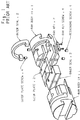
- FIG. 10(a), 10(b) and 10(c) A second apparatus for ensuring that a wireline is centralised within a wireline valve is shown in Figs. 10(a), 10(b) and 10(c). It should be noted that the apparatus shown in Figs. 10(a) to 10(c) is intended to be mounted above and below a conventional wireline valve as shown in Figs. 1, 2, 3(a) and 3(b), such that the apparatus as shown in Figs. 10(a) to 10(c) can be retrofitted to an existing wireline valve, or can be supplied to a user along with an existing wireline valve.
- the apparatus of Figs. 10(a) to 10(c) comprises a tubular sub 81, provided with suitable couplings such as screwthread couplings for coupling one tubular sub 81 above the wireline valve and one tubular sub 81 below the wireline valve.
- the tubular sub 81 is provided with a pair of apertures 83 formed in the sidewall thereof, where the apertures 83 are arranged to be diametrically opposite one another.
- a cylindrical shaft 85 is located in each of the apertures 83, where the cylindrical shaft 85 has two square recesses 87 formed thereon.
- a handle 89 having a square aperture therethrough is attached to one of the square recesses 87 of the shaft 85, such that rotation of the handle about the square coupling with the shaft 85 causes the shaft 85 to rotate.
- a semi-circular guide arm is coupled to the other square recess 87 such that rotation of the shaft causes rotation of the guide arm 91A.
- the other end of the semi-circular guide arm 91A is held in place by the other shaft 85, but rotation of the other shaft 85 does not cause rotation to occur to the semi-circular guide arm 91A.
- the other shaft 85 is secured to a handle (not shown) and is further secured via a similar square recess arrangement to a second semi-circular guide arm 91B, such that rotation of the other handle causes rotation to occur to the other semi-circular guide arm 91B.
- a shaft end cap 95 holds the shaft 85 in position, where the shaft end cap 95 is secured in place against the outer surface of the tubular sub 81 by means of a suitable bolt 97.
- tubular sub 81 is arranged so that the wireline valve rams are orientated so that they close in the plane of the arrow 100.
- the handles may be manually operated, or may be hydraulically driven.
- the very centre of the shaft 85 is hollow, and this provides the advantage that the junction between the shaft 85 and the end cap 95 will experience the same pressure as the main throughbore 97 which means that the rotation of the handle 89 should occur more easily.
- the shaft 85 is pressure balanced to remove end loads thereon.
- the guide arms preferably have rounded profiles to prevent damage occurring to the wireline 102 and the slot envelope provided by the two guide arms 91A, 91B coming together is large enough to suit the desired wireline 102 size.
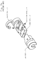
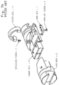
- FIGs. 11(a) and 11(b) show a second alternative embodiment for centralising a wireline 102.
- This embodiment comprises an outer tubular sub 110, one of which is coupled to the upper end of a wireline valve, and another of which is coupled to a lower end of the wireline valve.
- a lower plate 112 is mounted within the inner bore of the tubular sub 110 and is retained longitudinally in that position by means of a shoulder 113 of the housing 110, and a threaded retainer ring 114.
- the lower plate 112 is rotatable about the longitudinal axis of the throughbore of the tubular sub 110, and it may be that a thrust washer is located between the lower plate 112 and the shoulder 113 or threaded retainer 114.
- An upper plate 116 is mounted within the throughbore of the tubular sub 110, and is provided with a key 117 which protrudes outwardly from its outer radial surface, where the key 117 is arranged to lie in a longitudinally arranged slot 118 formed along the inner surface of the tubular sub 110. Accordingly, the key 117 prevents rotation of the upper plate 116, but permits longitudinal movement of the plate 116 with respect to the housing 110 and the lower plate 112.
- the upper plate 116 is coupled to the lower plate 112 via a plurality of rods or wires 120. It is preferred that there at least four rods 120.
- the rods 120 are each secured to the upper 116 and lower 112 plates via a suitable moveable joint such as spherical joint 122.
- Actuation of the apparatus shown in Figs. 11(a) and 11(b) causes the lower plate 112 to rotate; this rotational movement can be generated manually through an arrangement of gears, or can be generated by a linear hydraulic piston with the lower plate 112 being keyed into a helical slot formed in the tubular sub 110.
- This rotation of the lower plate 112 relative to the upper plate 116 causes the rods 120 to take the shortest route across the throughbore of the housing 110 and concurrently, the upper plate 116 is caused to move downwardly toward the lower plate 112 until it reaches its final position as shown in phantom as 116A.
- the plurality of rods 120 have caused a cage or envelope 124 about the longitudinal axis of the throughbore of the housing 110, and the wireline 102 is moved by the rods 120 to be located within this square cage/envelope 124.
- actuation of both upper 110 and lower 110 housings causes the wireline 102 to be located on the longitudinal axis of the wireline valve and hence the wireline 102 has been centralised on that longitudinal axis.
- a compression spring 126 is located between the upper 116 and lower 112 plates, and acts therebetween, such that removal of the rotational force to the lower plate 112 will cause the upper plate 116 to return to its starting position, as shown in Fig. 11(b).
- a tubular sub which may be similar to either of those previously described, is located above and below a conventional wireline valve.
- the tubular sub contains a plurality of fingers which normally reside out of the throughbore of the tubular sub, but which may be actuated in a rotary manner to bring the fingers into the throughbore of the tubular sub and reduce the bore size concentrically to an envelope just larger than the wire diameter.
- the plurality of fingers thus operate in a manner similar to the principle of a camera iris.
- wireline guides 18, 20, 58 and 60 are formed integrally with the respective cylindrical ram body, it is possible that the wireline guides 18, 20, 58 and 60 be replaceable, and in this latter scenario, suitable fixing means such as screws or bolts or the like would be used to replaceably secure the wireline guides 18, 20, 58 and 60 to the respective cylindrical ram body.
Landscapes
- Engineering & Computer Science (AREA)
- Geology (AREA)
- Mining & Mineral Resources (AREA)
- Life Sciences & Earth Sciences (AREA)
- General Life Sciences & Earth Sciences (AREA)
- Fluid Mechanics (AREA)
- Environmental & Geological Engineering (AREA)
- Physics & Mathematics (AREA)
- Geochemistry & Mineralogy (AREA)
- Mechanical Engineering (AREA)
- Media Introduction/Drainage Providing Device (AREA)
- Investigating Or Analyzing Materials By The Use Of Magnetic Means (AREA)
- Electrical Discharge Machining, Electrochemical Machining, And Combined Machining (AREA)
- Drilling And Boring (AREA)
- Diaphragms For Electromechanical Transducers (AREA)
- Multiple-Way Valves (AREA)
- Prostheses (AREA)
- Mechanically-Actuated Valves (AREA)
Applications Claiming Priority (2)
| Application Number | Priority Date | Filing Date | Title |
|---|---|---|---|
| GB0022157 | 2000-09-09 | ||
| GBGB0022157.2A GB0022157D0 (en) | 2000-09-09 | 2000-09-09 | Apparatus and method |
Publications (3)
| Publication Number | Publication Date |
|---|---|
| EP1186743A2 true EP1186743A2 (de) | 2002-03-13 |
| EP1186743A3 EP1186743A3 (de) | 2003-03-05 |
| EP1186743B1 EP1186743B1 (de) | 2004-10-27 |
Family
ID=9899162
Family Applications (1)
| Application Number | Title | Priority Date | Filing Date |
|---|---|---|---|
| EP01307675A Expired - Lifetime EP1186743B1 (de) | 2000-09-09 | 2001-09-10 | Vorrichtung und Verfahren zum Zentrieren eines Bohrlochseils |
Country Status (5)
| Country | Link |
|---|---|
| US (1) | US6676103B2 (de) |
| EP (1) | EP1186743B1 (de) |
| AT (1) | ATE280892T1 (de) |
| DE (1) | DE60106700D1 (de) |
| GB (2) | GB0022157D0 (de) |
Cited By (5)
| Publication number | Priority date | Publication date | Assignee | Title |
|---|---|---|---|---|
| EP1582692A3 (de) * | 2004-04-01 | 2006-03-01 | National-Oilwell, L.P. | Verfahren und Vorrichtung zur Zentrierung eines Elements |
| EP1865145A1 (de) * | 2006-06-03 | 2007-12-12 | Elmar Services Limited | Verfahren und Vorrichtung zur Abdichtung eines Loches mit einem durchquerenden Seil |
| GB2484741A (en) * | 2010-10-22 | 2012-04-25 | Weatherford Lamb | Restricting fluid flow in a bore with an actuator isolated from bore pressure |
| EP1853790A4 (de) * | 2005-03-02 | 2014-09-24 | Atlas Copco Rock Drills Ab | Bohrstangenstütze und stützhälfte einer bohrstange |
| WO2024097042A1 (en) * | 2022-10-31 | 2024-05-10 | Schlumberger Technology Corporation | Interlocking rams for a blowout preventer |
Families Citing this family (3)
| Publication number | Priority date | Publication date | Assignee | Title |
|---|---|---|---|---|
| GB201019744D0 (en) | 2010-11-22 | 2011-01-05 | Hunting Energy Services Well Intervention Ltd | Wireline valve apparatus and improved wireline ram |
| US11078758B2 (en) | 2018-08-09 | 2021-08-03 | Schlumberger Technology Corporation | Pressure control equipment systems and methods |
| SG10202008007SA (en) | 2019-08-20 | 2021-03-30 | Cameron Tech Ltd | Tool trap system |
Family Cites Families (14)
| Publication number | Priority date | Publication date | Assignee | Title |
|---|---|---|---|---|
| US3692316A (en) | 1970-12-21 | 1972-09-19 | Bowen Tools Inc | Wireline blowout preventer |
| US3880436A (en) * | 1973-07-05 | 1975-04-29 | Rucker Co | Ram block |
| US4372527A (en) * | 1980-05-05 | 1983-02-08 | Dresser Industries, Inc. | Blowout preventer |
| US4506858A (en) * | 1983-05-31 | 1985-03-26 | Otis Engineering Corporation | Wireline valve inner seal |
| US4646825A (en) | 1986-01-02 | 1987-03-03 | Winkle Denzal W Van | Blowout preventer, shear ram, shear blade and seal therefor |
| US5125620A (en) * | 1991-10-02 | 1992-06-30 | Hydril Company | Ram type blowout preventer having improved ram front packing |
| US5127623A (en) * | 1991-10-07 | 1992-07-07 | Petro-Flex Rubber Products, Inc. | Inner seal for ram-type blowout preventer |
| US5294088A (en) * | 1992-10-13 | 1994-03-15 | Cooper Industries, Inc. | Variable bore packer for a ram-type blowout preventer |
| US5287879A (en) | 1993-04-13 | 1994-02-22 | Eastern Oil Tools Pte Ltd. | Hydraulically energized wireline blowout preventer |
| US5400857A (en) | 1993-12-08 | 1995-03-28 | Varco Shaffer, Inc. | Oilfield tubular shear ram and method for blowout prevention |
| US5575451A (en) * | 1995-05-02 | 1996-11-19 | Hydril Company | Blowout preventer ram for coil tubing |
| US5603481A (en) * | 1996-01-24 | 1997-02-18 | Cooper Cameron Corporation | Front packer for ram-type blowout preventer |
| US5833208A (en) * | 1997-09-15 | 1998-11-10 | Jm Clipper Corporation | Inner seal for ram-type blowout preventer |
| GB9805120D0 (en) | 1998-03-11 | 1998-05-06 | British Gas Plc | Sliding plate valve |
-
2000
- 2000-09-09 GB GBGB0022157.2A patent/GB0022157D0/en not_active Ceased
-
2001
- 2001-09-07 US US09/949,094 patent/US6676103B2/en not_active Expired - Lifetime
- 2001-09-10 DE DE60106700T patent/DE60106700D1/de not_active Expired - Lifetime
- 2001-09-10 GB GB0121691A patent/GB2367575A/en not_active Withdrawn
- 2001-09-10 AT AT01307675T patent/ATE280892T1/de not_active IP Right Cessation
- 2001-09-10 EP EP01307675A patent/EP1186743B1/de not_active Expired - Lifetime
Cited By (8)
| Publication number | Priority date | Publication date | Assignee | Title |
|---|---|---|---|---|
| EP1582692A3 (de) * | 2004-04-01 | 2006-03-01 | National-Oilwell, L.P. | Verfahren und Vorrichtung zur Zentrierung eines Elements |
| US7111676B2 (en) | 2004-04-01 | 2006-09-26 | National-Oilwell, L.P. | Pipe centering device |
| EP1853790A4 (de) * | 2005-03-02 | 2014-09-24 | Atlas Copco Rock Drills Ab | Bohrstangenstütze und stützhälfte einer bohrstange |
| EP1865145A1 (de) * | 2006-06-03 | 2007-12-12 | Elmar Services Limited | Verfahren und Vorrichtung zur Abdichtung eines Loches mit einem durchquerenden Seil |
| US7611120B2 (en) | 2006-06-03 | 2009-11-03 | Elmar Services Limited | Method and apparatus |
| GB2484741A (en) * | 2010-10-22 | 2012-04-25 | Weatherford Lamb | Restricting fluid flow in a bore with an actuator isolated from bore pressure |
| GB2484741B (en) * | 2010-10-22 | 2017-03-01 | Weatherford Tech Holdings Llc | Apparatus and methods for restricting flow in a bore |
| WO2024097042A1 (en) * | 2022-10-31 | 2024-05-10 | Schlumberger Technology Corporation | Interlocking rams for a blowout preventer |
Also Published As
| Publication number | Publication date |
|---|---|
| EP1186743B1 (de) | 2004-10-27 |
| DE60106700D1 (de) | 2004-12-02 |
| US6676103B2 (en) | 2004-01-13 |
| GB2367575A (en) | 2002-04-10 |
| GB0022157D0 (en) | 2000-10-25 |
| GB0121691D0 (en) | 2001-10-31 |
| US20020070016A1 (en) | 2002-06-13 |
| ATE280892T1 (de) | 2004-11-15 |
| EP1186743A3 (de) | 2003-03-05 |
Similar Documents
| Publication | Publication Date | Title |
|---|---|---|
| US5400857A (en) | Oilfield tubular shear ram and method for blowout prevention | |
| US6601650B2 (en) | Method and apparatus for replacing BOP with gate valve | |
| US5284209A (en) | Coiled tubing cutting modification | |
| US12385349B2 (en) | Blowout preventer with multiple application ram blades | |
| DE69709075T2 (de) | Monoloch-riser auswahl-gerät | |
| AU2002331033A1 (en) | Method and apparatus for replacing BOP with gate valve | |
| US7510002B2 (en) | Apparatus and method for sealing a wellbore | |
| US6676103B2 (en) | Wireline centralization apparatus and method | |
| WO2017083123A1 (en) | Blowout preventer including shear body | |
| CA3073131C (en) | Valve seat and valve | |
| US8770541B2 (en) | Sealing apparatus and method | |
| EP2576960B1 (de) | Rohrtrennsystem und verwendungsverfahren dafür | |
| US12435594B2 (en) | Bore selector | |
| CN107002478B (zh) | 一种用于提取井的安全阀及用来关闭井的方法 | |
| US10954738B2 (en) | Dual compact cutting device intervention system | |
| EP1812680B1 (de) | Verbessertes ventil | |
| US9027645B2 (en) | Fishing tool | |
| EP4151827A1 (de) | Verbesserte scherklinge |
Legal Events
| Date | Code | Title | Description |
|---|---|---|---|
| PUAI | Public reference made under article 153(3) epc to a published international application that has entered the european phase |
Free format text: ORIGINAL CODE: 0009012 |
|
| AK | Designated contracting states |
Kind code of ref document: A2 Designated state(s): AT BE CH CY DE DK ES FI FR GB GR IE IT LI LU MC NL PT SE TR |
|
| AX | Request for extension of the european patent |
Free format text: AL;LT;LV;MK;RO;SI |
|
| RIC1 | Information provided on ipc code assigned before grant |
Free format text: 7E 21B 33/06 A |
|
| PUAL | Search report despatched |
Free format text: ORIGINAL CODE: 0009013 |
|
| AK | Designated contracting states |
Kind code of ref document: A3 Designated state(s): AT BE CH CY DE DK ES FI FR GB GR IE IT LI LU MC NL PT SE TR Designated state(s): AT BE CH CY DE DK ES FI FR GB GR IE IT LI LU MC NL PT SE TR |
|
| AX | Request for extension of the european patent |
Extension state: AL LT LV MK RO SI |
|
| 17P | Request for examination filed |
Effective date: 20030626 |
|
| 17Q | First examination report despatched |
Effective date: 20030904 |
|
| AKX | Designation fees paid |
Designated state(s): AT BE CH CY DE DK ES FI FR GB GR IE IT LI LU MC NL PT SE TR |
|
| GRAP | Despatch of communication of intention to grant a patent |
Free format text: ORIGINAL CODE: EPIDOSNIGR1 |
|
| GRAS | Grant fee paid |
Free format text: ORIGINAL CODE: EPIDOSNIGR3 |
|
| GRAA | (expected) grant |
Free format text: ORIGINAL CODE: 0009210 |
|
| AK | Designated contracting states |
Kind code of ref document: B1 Designated state(s): AT BE CH CY DE DK ES FI FR GB GR IE IT LI LU MC NL PT SE TR |
|
| PG25 | Lapsed in a contracting state [announced via postgrant information from national office to epo] |
Ref country code: TR Free format text: LAPSE BECAUSE OF FAILURE TO SUBMIT A TRANSLATION OF THE DESCRIPTION OR TO PAY THE FEE WITHIN THE PRESCRIBED TIME-LIMIT Effective date: 20041027 Ref country code: LI Free format text: LAPSE BECAUSE OF FAILURE TO SUBMIT A TRANSLATION OF THE DESCRIPTION OR TO PAY THE FEE WITHIN THE PRESCRIBED TIME-LIMIT Effective date: 20041027 Ref country code: FI Free format text: LAPSE BECAUSE OF FAILURE TO SUBMIT A TRANSLATION OF THE DESCRIPTION OR TO PAY THE FEE WITHIN THE PRESCRIBED TIME-LIMIT Effective date: 20041027 Ref country code: CH Free format text: LAPSE BECAUSE OF FAILURE TO SUBMIT A TRANSLATION OF THE DESCRIPTION OR TO PAY THE FEE WITHIN THE PRESCRIBED TIME-LIMIT Effective date: 20041027 Ref country code: BE Free format text: LAPSE BECAUSE OF FAILURE TO SUBMIT A TRANSLATION OF THE DESCRIPTION OR TO PAY THE FEE WITHIN THE PRESCRIBED TIME-LIMIT Effective date: 20041027 Ref country code: AT Free format text: LAPSE BECAUSE OF FAILURE TO SUBMIT A TRANSLATION OF THE DESCRIPTION OR TO PAY THE FEE WITHIN THE PRESCRIBED TIME-LIMIT Effective date: 20041027 |
|
| REG | Reference to a national code |
Ref country code: GB Ref legal event code: FG4D |
|
| REG | Reference to a national code |
Ref country code: CH Ref legal event code: EP |
|
| REG | Reference to a national code |
Ref country code: IE Ref legal event code: FG4D |
|
| REF | Corresponds to: |
Ref document number: 60106700 Country of ref document: DE Date of ref document: 20041202 Kind code of ref document: P |
|
| PG25 | Lapsed in a contracting state [announced via postgrant information from national office to epo] |
Ref country code: SE Free format text: LAPSE BECAUSE OF FAILURE TO SUBMIT A TRANSLATION OF THE DESCRIPTION OR TO PAY THE FEE WITHIN THE PRESCRIBED TIME-LIMIT Effective date: 20050127 Ref country code: GR Free format text: LAPSE BECAUSE OF FAILURE TO SUBMIT A TRANSLATION OF THE DESCRIPTION OR TO PAY THE FEE WITHIN THE PRESCRIBED TIME-LIMIT Effective date: 20050127 Ref country code: DK Free format text: LAPSE BECAUSE OF FAILURE TO SUBMIT A TRANSLATION OF THE DESCRIPTION OR TO PAY THE FEE WITHIN THE PRESCRIBED TIME-LIMIT Effective date: 20050127 |
|
| PG25 | Lapsed in a contracting state [announced via postgrant information from national office to epo] |
Ref country code: DE Free format text: LAPSE BECAUSE OF FAILURE TO SUBMIT A TRANSLATION OF THE DESCRIPTION OR TO PAY THE FEE WITHIN THE PRESCRIBED TIME-LIMIT Effective date: 20050128 |
|
| PG25 | Lapsed in a contracting state [announced via postgrant information from national office to epo] |
Ref country code: ES Free format text: LAPSE BECAUSE OF FAILURE TO SUBMIT A TRANSLATION OF THE DESCRIPTION OR TO PAY THE FEE WITHIN THE PRESCRIBED TIME-LIMIT Effective date: 20050207 |
|
| REG | Reference to a national code |
Ref country code: CH Ref legal event code: PL |
|
| ET | Fr: translation filed | ||
| PLBE | No opposition filed within time limit |
Free format text: ORIGINAL CODE: 0009261 |
|
| STAA | Information on the status of an ep patent application or granted ep patent |
Free format text: STATUS: NO OPPOSITION FILED WITHIN TIME LIMIT |
|
| PG25 | Lapsed in a contracting state [announced via postgrant information from national office to epo] |
Ref country code: CY Free format text: LAPSE BECAUSE OF FAILURE TO SUBMIT A TRANSLATION OF THE DESCRIPTION OR TO PAY THE FEE WITHIN THE PRESCRIBED TIME-LIMIT Effective date: 20050910 |
|
| PG25 | Lapsed in a contracting state [announced via postgrant information from national office to epo] |
Ref country code: MC Free format text: LAPSE BECAUSE OF NON-PAYMENT OF DUE FEES Effective date: 20050930 Ref country code: LU Free format text: LAPSE BECAUSE OF NON-PAYMENT OF DUE FEES Effective date: 20050930 |
|
| 26N | No opposition filed |
Effective date: 20050728 |
|
| PG25 | Lapsed in a contracting state [announced via postgrant information from national office to epo] |
Ref country code: PT Free format text: LAPSE BECAUSE OF NON-PAYMENT OF DUE FEES Effective date: 20050327 |
|
| REG | Reference to a national code |
Ref country code: NL Ref legal event code: SD Effective date: 20100614 |
|
| REG | Reference to a national code |
Ref country code: GB Ref legal event code: 732E Free format text: REGISTERED BETWEEN 20100708 AND 20100714 |
|
| REG | Reference to a national code |
Ref country code: FR Ref legal event code: TP |
|
| PG25 | Lapsed in a contracting state [announced via postgrant information from national office to epo] |
Ref country code: IT Free format text: LAPSE BECAUSE OF NON-PAYMENT OF DUE FEES Effective date: 20100910 |
|
| PGRI | Patent reinstated in contracting state [announced from national office to epo] |
Ref country code: IT Effective date: 20110616 |
|
| REG | Reference to a national code |
Ref country code: FR Ref legal event code: PLFP Year of fee payment: 16 |
|
| REG | Reference to a national code |
Ref country code: FR Ref legal event code: PLFP Year of fee payment: 17 |
|
| REG | Reference to a national code |
Ref country code: FR Ref legal event code: PLFP Year of fee payment: 18 |
|
| PGFP | Annual fee paid to national office [announced via postgrant information from national office to epo] |
Ref country code: IE Payment date: 20190910 Year of fee payment: 19 Ref country code: NL Payment date: 20190912 Year of fee payment: 19 |
|
| PGFP | Annual fee paid to national office [announced via postgrant information from national office to epo] |
Ref country code: GB Payment date: 20200902 Year of fee payment: 20 Ref country code: FR Payment date: 20200812 Year of fee payment: 20 |
|
| PGFP | Annual fee paid to national office [announced via postgrant information from national office to epo] |
Ref country code: IT Payment date: 20200812 Year of fee payment: 20 |
|
| REG | Reference to a national code |
Ref country code: NL Ref legal event code: MM Effective date: 20201001 |
|
| PG25 | Lapsed in a contracting state [announced via postgrant information from national office to epo] |
Ref country code: NL Free format text: LAPSE BECAUSE OF NON-PAYMENT OF DUE FEES Effective date: 20201001 |
|
| PG25 | Lapsed in a contracting state [announced via postgrant information from national office to epo] |
Ref country code: IE Free format text: LAPSE BECAUSE OF NON-PAYMENT OF DUE FEES Effective date: 20200910 |
|
| REG | Reference to a national code |
Ref country code: GB Ref legal event code: PE20 Expiry date: 20210909 |
|
| PG25 | Lapsed in a contracting state [announced via postgrant information from national office to epo] |
Ref country code: GB Free format text: LAPSE BECAUSE OF EXPIRATION OF PROTECTION Effective date: 20210909 |