EP1186485A2 - Device for regulating inflation of an airbag - Google Patents
Device for regulating inflation of an airbag Download PDFInfo
- Publication number
- EP1186485A2 EP1186485A2 EP01119813A EP01119813A EP1186485A2 EP 1186485 A2 EP1186485 A2 EP 1186485A2 EP 01119813 A EP01119813 A EP 01119813A EP 01119813 A EP01119813 A EP 01119813A EP 1186485 A2 EP1186485 A2 EP 1186485A2
- Authority
- EP
- European Patent Office
- Prior art keywords
- inflation
- aperture
- shutter
- airbag
- energy store
- Prior art date
- Legal status (The legal status is an assumption and is not a legal conclusion. Google has not performed a legal analysis and makes no representation as to the accuracy of the status listed.)
- Granted
Links
- 230000001105 regulatory effect Effects 0.000 title claims abstract description 6
- 239000003380 propellant Substances 0.000 claims description 4
- 239000007789 gas Substances 0.000 description 22
- 238000000034 method Methods 0.000 description 7
- 230000004913 activation Effects 0.000 description 3
- XKRFYHLGVUSROY-UHFFFAOYSA-N Argon Chemical compound [Ar] XKRFYHLGVUSROY-UHFFFAOYSA-N 0.000 description 2
- 230000002035 prolonged effect Effects 0.000 description 2
- 238000007789 sealing Methods 0.000 description 2
- 229910052786 argon Inorganic materials 0.000 description 1
- 230000001419 dependent effect Effects 0.000 description 1
- 238000010586 diagram Methods 0.000 description 1
- 230000000694 effects Effects 0.000 description 1
- 239000001307 helium Substances 0.000 description 1
- 229910052734 helium Inorganic materials 0.000 description 1
- SWQJXJOGLNCZEY-UHFFFAOYSA-N helium atom Chemical compound [He] SWQJXJOGLNCZEY-UHFFFAOYSA-N 0.000 description 1
- 239000000203 mixture Substances 0.000 description 1
- 238000000465 moulding Methods 0.000 description 1
Images


Classifications
-
- B—PERFORMING OPERATIONS; TRANSPORTING
- B60—VEHICLES IN GENERAL
- B60R—VEHICLES, VEHICLE FITTINGS, OR VEHICLE PARTS, NOT OTHERWISE PROVIDED FOR
- B60R21/00—Arrangements or fittings on vehicles for protecting or preventing injuries to occupants or pedestrians in case of accidents or other traffic risks
- B60R21/02—Occupant safety arrangements or fittings, e.g. crash pads
- B60R21/16—Inflatable occupant restraints or confinements designed to inflate upon impact or impending impact, e.g. air bags
- B60R21/26—Inflatable occupant restraints or confinements designed to inflate upon impact or impending impact, e.g. air bags characterised by the inflation fluid source or means to control inflation fluid flow
- B60R21/263—Inflatable occupant restraints or confinements designed to inflate upon impact or impending impact, e.g. air bags characterised by the inflation fluid source or means to control inflation fluid flow using a variable source, e.g. plural stage or controlled output
- B60R2021/2633—Inflatable occupant restraints or confinements designed to inflate upon impact or impending impact, e.g. air bags characterised by the inflation fluid source or means to control inflation fluid flow using a variable source, e.g. plural stage or controlled output with a plurality of inflation levels
Definitions
- the present invention relates to a device for inflating an airbag of a motor vehicle and regulating the amount of inflation gas supplied to an airbag according to claim 1.
- EP 0 812 741 A1 teaches a device for regulating the amount of inflation gas supplied to an airbag of a motor vehicle comprising inflation apertures in several cylindrical members.
- An adjustable shutter can open the cross section of the apertures completely or partially. The adjustment of the aperture cross section of each inflation aperture is dependent on the position of the vehicle occupant to be protected or on objects such as children's seats and the like that are located in the path of the airbag when it is deployed.
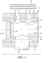
- Each of the embodiments shown in the Figs. has an inflation head 12 that is attached to a vessel 1, preferably a substantially cylindrical-shaped vessel, containing inflation gas, which is shown only in Fig. 1.
- the inflation head can be connected to the source of inflation gas using a weld joint.
- the source of inflation gas 1 which is preferably a cylindrical-shaped storage vessel containing cold gas, is closed by a sealing disk 24.
- the inflation gas preferably comprises a gas such as helium or argon, or a mixture of both such gases, stored at a high pressure of, for instance, approximately 600 bar.
- the inflation head directs the inflation gas exiting from the storage vessel towards the interior of the airbag
- the inflation head 12 comprises a cylindrical inflation head casing 25, which is a cylindrical member that has a cylindrical exterior surface 4.
- a closure 30 is located at the end of the inflation head casing that is distal from the gas storage vessel 1.
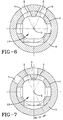
- An annular shutter 9 is rotatably mounted on the cylindrical exterior surface of the inflation head casing. During normal driving conditions the annular shutter 9 is arranged on the outer cylindrical surface of the inflation head with a press fit. As shown in Figs. 1, 2 and 6, the shutter apertures 7, 8 in the annular shutter 9 are aligned with inflation apertures 2, 3 in the inflation head casing 25. In the represented embodiment, four inflation apertures 2, 3 and four corresponding shutter apertures 7, 8 can be provided. As shown in the Figs.
- the cross sections of the inflation apertures 2, 3 and the shutter apertures 7, 8 are the same. It is preferable that the inflation apertures 2, 3 and the shutter apertures 7, 8 are radially and axially aligned in relation to an axis 5 of the cylindrical inflation head casing 25.
- the inflation apertures and shutter apertures are directed towards the interior of an airbag 13, which under normal driving conditions is folded and located in a housing 19 as shown in Fig. 2.
- each shutter aperture 7, 8 and a corresponding inflation aperture 2, 3 When a shutter aperture 7, 8 and a corresponding inflation aperture 2, 3 are aligned with one another, the entire cross section of the inflation aperture is completely opened towards the interior of the airbag.
- Each shutter aperture can be moved to completely, or partially, close the corresponding inflation aperture.
- the position of the shutter aperture with respect to the corresponding inflation aperture preferably depends on the position of the vehicle occupant to be protected or on an object, such as child's seats, that is located in the path of deployment of the airbag.
- the position of the vehicle occupant can be detected in a known manner by position sensors. It is also possible to carry out an advance movement sensing of the airbag simultaneously to the inflation process of the airbag and to complete the inflation process by closing the respective inflation aperture in dependence on the sensed free path length. Such a sensing process is known from EP 0 812 741 A1.
- the process of inflating the airbag 13 can be prematurely ended by closing the inflation apertures 2, 3.
- the energy store 10 can comprise an ignitable pyrotechnical propellant that when activated acts upon a lever arm 22 firmly attached to the annular shutter 9. As a result, the shutter is brought from the positions shown in Figs. 2 or 6 to the closing position shown in Figs. 3 or 7, in which the inflation apertures 2, 3 are closed.
- the annular shutter 9 is then pivoted by an angle ⁇ as shown in Fig. 7 around the axis 5 of the cylindrical inflation head 25. A short-term or pulsed control of the shutter position is thus achieved.
- the advance movement sensing can take place with the help of a corresponding advance movement sensing device 18, as shown in Fig. 8, which is connected to a control device 16 for the energy store 10.
- Said advance movement sensing device 18 can be designed in the manner known from EP 0 812 741 A1 or US 6 129 379.
- An Out-Of-Position vehicle occupant can be identified in a known manner using one or several position sensors 17. This allows the amount of gas needed to fill the airbag 13 to be predicted, and the closing movement of the annular shutter 9 through the corresponding control of the energy store 10 to be initiated after a predetermined time.
- the annular shutter can have an annular recess 21, the boundary of which comprises an abutment 26 that is fitted to the side boundary of the pyrotechnic device 20, when the annular shutter 9 pivots around the pivoting angle ⁇ , shown in Fig. 7, into the closing position, shown in Fig. 3.
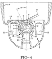
- the shutter device 6 comprises an energy store 10 to bring the annular shutter 9 into the closing position shown in Fig. 3, whereas in the embodiment shown in Figs. 4 and 5, the shutter device 6 comprises two energy stores 10, 11.
- the annular shutter 9 is pivoted in opposite directions by the angle ⁇ .
- Fig. 4 shows the closing position of the annular shutter 9.
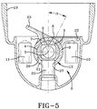
- Fig. 5 shows the inflation position of the annular shutter, in which the aperture cross section of the inflation apertures 2, 3 is completely open towards the interior of the airbag.
- the position represented in Fig. 5 also corresponds to the position assumed by the annular shutter 9 under normal driving conditions. This position can be defined by an end abutment 27 in the annular opening 21 of the annular shutter.
- Said end abutment 27 is fitted to the side of the pyrotechnic device 20, as can be seen in Fig. 5.
- An abutment of this type can also be employed in the embodiment shown in Figs. 2 and 3.
- the length of the arc, along which the aperture 29 of the annular shutter 90 extends, corresponds to the pivoting angle ⁇ , within which the annular shutter 9 is moved around the axis 5, between its closing and open position.
- Figs. 4 and 5 has special advantage s if the vehicle experiences a crash involving multiple impacts.
- the airbag is inflated through the aligned inflation apertures 2, 3 and shutter apertures 7, 8 which assume the position shown in Fig. 5.
- the amount of inflation gas that is supplied to the interior of the airbag is calculated with relation to the free length of advance movement of the airbag during inflation and/or on the sitting position of the vehicle occupant measured by sensors.
- the annular shutter 9 is brought into the closing position shown in Fig. 4. If during the crash a second impact occurs, the second energy store 11 is activated.
- This activation can take place as a result of sensor signals of one or several motor vehicle sensors 14, 15 which are connected to the control device 16.
- the activated energy store 11 which can contain a pyrotechnical propellant, acts upon a second lever arm 23, which is firmly connected to the annular shutter 9.
- the annular shutter is thus brought back to the open position shown in Fig. 5, so that more inflation gas can be supplied to the interior of the airbag.
- the inflation gas contained in the vessel 1 under high pressure, for instance 600 bar, and the amount of inflation gas is sufficient to inflate the airbag two times.
- the inflated volume of the passenger side airbag equals about 100 to 130 liters.
- the inflation time within which said inflation volume is achieved with a fully inflated airbag equals 30 to 35ms.
- the embodiment shown in Figs. 4 and 5 is particularly advantageous when during a crash the vehicle sustains several crashes within a short space of time. With this embodiment the inflation of the airbag can be prolonged.
- the annular shutter 9 and the axis 5 are rotatably mounted.
- the two lever arms 22, 23, which act as actuating levers, are fixed to the annular shutter, for example by molding on. Both lever arms 22, 23 are arranged around the axis 5 of the annular shutter at a predetermined offset angle of about 180° - ⁇ .
- the annular shutter 9 is rotatably mounted around the axis 5. It is of course also possible to arrange this embodiment in such a way that the annular shutter 9 is moved along a helical line on the exterior surface of the inflation head casing 25. To this effect a simple helical guide is to be provided between the screw head casing and the annular shutter.
- pre-crash sensor signals that predict the likelihood of a crash to control the aperture cross section of the corresponding inflation aperture.
- the amount of inflation gas which is to be supplied to the airbag can be preset.
Landscapes
- Physics & Mathematics (AREA)
- Fluid Mechanics (AREA)
- Engineering & Computer Science (AREA)
- Mechanical Engineering (AREA)
- Air Bags (AREA)
Abstract
Description
Claims (9)
- A device for regulating the amount of inflation gas supplied to an airbag (13) of a motor vehicle comprising a cylindrical member (25) having at least one inflation aperture (2, 3) therethrough and an annular shutter (9) having at least one shutter aperture (7, 8) therein is rotatable around the axis of the cylindrical member such that the amount of inflation gas which is supplied via the at least one inflation aperture is adjustable, the at least one shutter aperture has an aperture cross section that corresponds to the aperture cross section of the at least one inflation aperture , whereby the aperture cross section of the at least one shutter aperture can be completely or partly aligned with the cross section of the aperture of the at least one inflation aperture.
- The device according to claim 1 wherein each shutter aperture (7, 8) and the corresponding inflation aperture (2, 3) is directed radially outwards around with relation to the axis of the cylindrical member (25).
- The device according to claim 1 wherein the annular shutter (9) is mounted with a press fit on the cylindrical member (25).
- The device according to claim 2 wherein the annular shutter (9) is mounted with a press fit on the cylindrical member (25).
- The device according to claim 1 further comprising at least one energy store (10, 11) that can be activated to adjust the annular shutter (9).
- The device according to claim 1 further comprising at least two energy stores (10, 11) that can be activated by a control device (16) in such a way that after the inflation of the airbag (13) the at least one inflation aperture (2, 3) is closed by the annular shutter (9) rotated by the first activated energy store and in the event of a subsequent second the at least one inflation aperture is reopened by the annular shutter rotated by the second activated energy store.
- The device according to claim 6 wherein the first energy store (10, 11) can be activated depending on the sensed sitting position of a vehicle occupant for the closing of the at least one inflation aperture (2, 3).
- The device according to claim 5 wherein the energy store (10, 11) comprises a pyrotechnic propellant.
- The device according to claim 6 wherein each energy store (10, 11) comprises a pyrotechnic propellant.
Applications Claiming Priority (2)
| Application Number | Priority Date | Filing Date | Title |
|---|---|---|---|
| DE10045035A DE10045035B4 (en) | 2000-09-12 | 2000-09-12 | Device for adjusting a filling gas quantity for an airbag |
| DE10045035 | 2000-09-12 |
Publications (3)
| Publication Number | Publication Date |
|---|---|
| EP1186485A2 true EP1186485A2 (en) | 2002-03-13 |
| EP1186485A3 EP1186485A3 (en) | 2003-11-26 |
| EP1186485B1 EP1186485B1 (en) | 2006-05-10 |
Family
ID=7655904
Family Applications (1)
| Application Number | Title | Priority Date | Filing Date |
|---|---|---|---|
| EP01119813A Expired - Lifetime EP1186485B1 (en) | 2000-09-12 | 2001-08-16 | Device for regulating inflation of an airbag |
Country Status (3)
| Country | Link |
|---|---|
| US (1) | US6572140B2 (en) |
| EP (1) | EP1186485B1 (en) |
| DE (2) | DE10045035B4 (en) |
Cited By (2)
| Publication number | Priority date | Publication date | Assignee | Title |
|---|---|---|---|---|
| WO2004071820A1 (en) * | 2003-02-06 | 2004-08-26 | Key Safety Systems, Inc. | Airbag module for selectively venting airbag inflation gas |
| CN109629529A (en) * | 2019-01-25 | 2019-04-16 | 天津大学 | A kind of gate Vertical Vibration Reduction and root edge adjustable systems |
Families Citing this family (8)
| Publication number | Priority date | Publication date | Assignee | Title |
|---|---|---|---|---|
| DE10311062B4 (en) * | 2003-03-13 | 2006-07-27 | Key Safety Systems, Inc., Sterling Heights | Gas mass control for airbags |
| DE10361887A1 (en) * | 2003-12-19 | 2005-07-14 | Takata-Petri Ag | Airbag device for a motor vehicle |
| US7890263B2 (en) * | 2005-04-08 | 2011-02-15 | Ford Global Technologies, Llc | System and method for sensing and deployment control supervision of a safety device |
| FR2890022B1 (en) * | 2005-09-01 | 2007-10-12 | Livbag Soc Par Actions Simplif | PYROTECHNIC GAS GENERATOR COMPRISING MEANS FOR TEMPORARILY STORING A PART OF GASES |
| DE102007004176A1 (en) * | 2007-01-27 | 2008-07-31 | Autoliv Development Ab | Method for variable filling of airbags, involves activating compressed gas source and ventilation unit with appropriate sensor data, and multiple gas discharge openings of gas producer unit are in fluidic connection with airbag |
| FR2998846B1 (en) * | 2012-12-04 | 2016-04-01 | Autoliv Dev | ADAPTIVE GAS GENERATOR FOR PROTECTIVE CUSHION |
| KR101756005B1 (en) * | 2016-04-04 | 2017-07-20 | 현대자동차주식회사 | Front airbag for vehicle and method for controlling the same |
| DE102018008893A1 (en) | 2018-11-12 | 2019-05-16 | Daimler Ag | Device for adjusting a gas flow of a gas generator |
Family Cites Families (20)
| Publication number | Priority date | Publication date | Assignee | Title |
|---|---|---|---|---|
| US3792872A (en) * | 1972-04-25 | 1974-02-19 | Gen Motors Corp | Occupant restraint system |
| DE3842145A1 (en) * | 1988-12-15 | 1990-06-28 | Bayern Chemie Gmbh Flugchemie | GAS GENERATOR, ESPECIALLY FOR THE INFLATABLE PROTECTIVE BAG OF AN IMPACT PROTECTION SYSTEM FOR VEHICLE occupants |
| JPH06199202A (en) * | 1993-01-06 | 1994-07-19 | Takata Kk | Inflater and air bag device for drivers seat |
| DE19519678A1 (en) * | 1995-05-30 | 1996-12-05 | Temic Bayern Chem Airbag Gmbh | Gas generator with adjustable gas flow |
| EP0812741B1 (en) * | 1996-03-22 | 2001-12-05 | HS Technik und Design Technische Entwicklungen GmbH | Air bag device in a motor vehicle |
| US5707078A (en) * | 1996-11-26 | 1998-01-13 | Takata, Inc. | Air bag module with adjustable cushion inflation |
| US6168199B1 (en) * | 1997-09-04 | 2001-01-02 | Trw Vehicle Safety Systems Inc. | Inflator for an inflatable vehicle occupant protection device |
| EP0917996A2 (en) * | 1997-11-19 | 1999-05-26 | Hygrama Ag | Airbag device for a vehicle |
| US6135503A (en) | 1997-11-21 | 2000-10-24 | Giesecke & Devrient Gmbh | Identification document |
| WO1999042340A1 (en) * | 1998-02-19 | 1999-08-26 | Breed Automotive Technology, Inc. | Exhaust regulators for airbag inflator systems |
| US6022045A (en) * | 1998-03-23 | 2000-02-08 | Trw Vehicle Safety Systems Inc. | Vehicle occupant protection apparatus |
| US5851029A (en) * | 1998-03-24 | 1998-12-22 | Barney Klinger | Gas pressure restraint, sensing and release systems |
| US6123358A (en) * | 1998-05-11 | 2000-09-26 | General Motors Corporation | Air bag module with variable inflation |
| US6241279B1 (en) * | 1998-05-26 | 2001-06-05 | Honda Giken Kogyo Kabushiki Kaisha | Air bag device |
| DE19839283A1 (en) * | 1998-08-28 | 2000-03-09 | Breed Automotive Tech | Airbag module with gas distributor |
| KR100268093B1 (en) * | 1998-08-31 | 2001-04-02 | 정몽규 | Car airbag device |
| US6213502B1 (en) * | 1998-11-24 | 2001-04-10 | Delphi Technologies, Inc. | Air bag module with variable inflation |
| WO2000043242A1 (en) * | 1999-01-21 | 2000-07-27 | Barney Klinger | Occupant-sensitive vehicular gas pressure restraint systems |
| US6439603B2 (en) * | 1999-10-13 | 2002-08-27 | Delphi Technologies, Inc. | Air bag module with variable inflation |
| US6371517B1 (en) * | 1999-12-28 | 2002-04-16 | Delphi Technologies, Inc. | Adaptive inflation mechanism |
-
2000
- 2000-09-12 DE DE10045035A patent/DE10045035B4/en not_active Expired - Fee Related
-
2001
- 2001-06-29 US US09/895,747 patent/US6572140B2/en not_active Expired - Lifetime
- 2001-08-16 EP EP01119813A patent/EP1186485B1/en not_active Expired - Lifetime
- 2001-08-16 DE DE60119457T patent/DE60119457D1/en not_active Expired - Lifetime
Cited By (3)
| Publication number | Priority date | Publication date | Assignee | Title |
|---|---|---|---|---|
| WO2004071820A1 (en) * | 2003-02-06 | 2004-08-26 | Key Safety Systems, Inc. | Airbag module for selectively venting airbag inflation gas |
| US7055856B2 (en) | 2003-02-06 | 2006-06-06 | Key Safety Systems, Inc. | Airbag module for selectively venting airbag inflation gas |
| CN109629529A (en) * | 2019-01-25 | 2019-04-16 | 天津大学 | A kind of gate Vertical Vibration Reduction and root edge adjustable systems |
Also Published As
| Publication number | Publication date |
|---|---|
| US20020030354A1 (en) | 2002-03-14 |
| DE10045035A1 (en) | 2002-04-04 |
| DE10045035B4 (en) | 2005-12-01 |
| EP1186485B1 (en) | 2006-05-10 |
| DE60119457D1 (en) | 2006-06-14 |
| EP1186485A3 (en) | 2003-11-26 |
| US6572140B2 (en) | 2003-06-03 |
Similar Documents
| Publication | Publication Date | Title |
|---|---|---|
| EP1319558B1 (en) | Opening device for a cold gas inflator | |
| US6428041B1 (en) | Airbag system for a motor vehicle | |
| EP1899200B1 (en) | Airbag tether release mechanism | |
| US8157291B2 (en) | Safety arrangement for a vehicle and method for controlling a safety arrangement | |
| US7946618B2 (en) | Airbag device | |
| JP2003504272A (en) | Occupant protection device for automobile steering wheel | |
| US6799777B2 (en) | Apparatus and methods of venting gas in an airbag module | |
| US6572140B2 (en) | Device for regulating inflation of an airbag | |
| JP4982572B2 (en) | Crew restraint system | |
| US7347449B2 (en) | Inflator having a variable gas flow throttle | |
| JPH1016699A (en) | Safety device of car | |
| HUT60198A (en) | Inflatable gas bag for keeping-back systems applicable in vehicles | |
| KR20000057577A (en) | A method of filling an empty, flexible container, and a container device | |
| US6357787B2 (en) | Gas bag module cover | |
| JP4595246B2 (en) | Vehicle occupant protection device | |
| JP4213663B2 (en) | Improvement of airbag device | |
| US12077125B2 (en) | Airbag deflation device, and vehicle seat | |
| JPH0640305A (en) | Air bag pressure adjusting device | |
| US6669232B2 (en) | Device for inflating an airbag | |
| EP1453706B1 (en) | Opening device for a cold gas inflator | |
| JP2005067272A (en) | Ceiling structure of vehicles equipped with airbags | |
| GB2353771A (en) | A device for holding a door onto a vehicle in the event of a crash | |
| JP4534479B2 (en) | Airbag device | |
| JPH11222096A (en) | Air bag device for vehicle and method to drive this air bag device | |
| JPH06227349A (en) | Side airbag device |
Legal Events
| Date | Code | Title | Description |
|---|---|---|---|
| PUAI | Public reference made under article 153(3) epc to a published international application that has entered the european phase |
Free format text: ORIGINAL CODE: 0009012 |
|
| AK | Designated contracting states |
Kind code of ref document: A2 Designated state(s): AT BE CH CY DE DK ES FI FR GB GR IE IT LI LU MC NL PT SE TR |
|
| AX | Request for extension of the european patent |
Free format text: AL;LT;LV;MK;RO;SI |
|
| PUAL | Search report despatched |
Free format text: ORIGINAL CODE: 0009013 |
|
| AK | Designated contracting states |
Kind code of ref document: A3 Designated state(s): AT BE CH CY DE DK ES FI FR GB GR IE IT LI LU MC NL PT SE TR |
|
| AX | Request for extension of the european patent |
Extension state: AL LT LV MK RO SI |
|
| 17P | Request for examination filed |
Effective date: 20040512 |
|
| AKX | Designation fees paid |
Designated state(s): DE FR GB IT |
|
| 17Q | First examination report despatched |
Effective date: 20040804 |
|
| GRAP | Despatch of communication of intention to grant a patent |
Free format text: ORIGINAL CODE: EPIDOSNIGR1 |
|
| GRAS | Grant fee paid |
Free format text: ORIGINAL CODE: EPIDOSNIGR3 |
|
| RAP1 | Party data changed (applicant data changed or rights of an application transferred) |
Owner name: KEY SAFETY SYSTEMS, INC. |
|
| GRAA | (expected) grant |
Free format text: ORIGINAL CODE: 0009210 |
|
| AK | Designated contracting states |
Kind code of ref document: B1 Designated state(s): DE FR GB IT |
|
| REG | Reference to a national code |
Ref country code: GB Ref legal event code: FG4D |
|
| REF | Corresponds to: |
Ref document number: 60119457 Country of ref document: DE Date of ref document: 20060614 Kind code of ref document: P |
|
| PG25 | Lapsed in a contracting state [announced via postgrant information from national office to epo] |
Ref country code: DE Free format text: LAPSE BECAUSE OF FAILURE TO SUBMIT A TRANSLATION OF THE DESCRIPTION OR TO PAY THE FEE WITHIN THE PRESCRIBED TIME-LIMIT Effective date: 20060811 |
|
| ET | Fr: translation filed | ||
| PLBE | No opposition filed within time limit |
Free format text: ORIGINAL CODE: 0009261 |
|
| STAA | Information on the status of an ep patent application or granted ep patent |
Free format text: STATUS: NO OPPOSITION FILED WITHIN TIME LIMIT |
|
| 26N | No opposition filed |
Effective date: 20070213 |
|
| PGFP | Annual fee paid to national office [announced via postgrant information from national office to epo] |
Ref country code: FR Payment date: 20080807 Year of fee payment: 8 Ref country code: IT Payment date: 20080816 Year of fee payment: 8 |
|
| PGFP | Annual fee paid to national office [announced via postgrant information from national office to epo] |
Ref country code: GB Payment date: 20090708 Year of fee payment: 9 |
|
| REG | Reference to a national code |
Ref country code: FR Ref legal event code: ST Effective date: 20100430 |
|
| PG25 | Lapsed in a contracting state [announced via postgrant information from national office to epo] |
Ref country code: FR Free format text: LAPSE BECAUSE OF NON-PAYMENT OF DUE FEES Effective date: 20090831 |
|
| PG25 | Lapsed in a contracting state [announced via postgrant information from national office to epo] |
Ref country code: IT Free format text: LAPSE BECAUSE OF NON-PAYMENT OF DUE FEES Effective date: 20090816 |
|
| GBPC | Gb: european patent ceased through non-payment of renewal fee |
Effective date: 20100816 |
|
| PG25 | Lapsed in a contracting state [announced via postgrant information from national office to epo] |
Ref country code: GB Free format text: LAPSE BECAUSE OF NON-PAYMENT OF DUE FEES Effective date: 20100816 |