EP1186443A2 - Method for securing a wheel applique to a wheel - Google Patents
Method for securing a wheel applique to a wheel Download PDFInfo
- Publication number
- EP1186443A2 EP1186443A2 EP01306029A EP01306029A EP1186443A2 EP 1186443 A2 EP1186443 A2 EP 1186443A2 EP 01306029 A EP01306029 A EP 01306029A EP 01306029 A EP01306029 A EP 01306029A EP 1186443 A2 EP1186443 A2 EP 1186443A2
- Authority
- EP
- European Patent Office
- Prior art keywords
- wheel
- applique
- vehicle wheel
- rim flange
- vehicle
- Prior art date
- Legal status (The legal status is an assumption and is not a legal conclusion. Google has not performed a legal analysis and makes no representation as to the accuracy of the status listed.)
- Withdrawn
Links
- 238000000034 method Methods 0.000 title claims abstract description 30
- 238000010438 heat treatment Methods 0.000 claims abstract description 10
- 241000239290 Araneae Species 0.000 claims description 21
- 238000004381 surface treatment Methods 0.000 claims description 9
- 238000001816 cooling Methods 0.000 claims description 6
- 239000000565 sealant Substances 0.000 claims description 5
- 238000004519 manufacturing process Methods 0.000 claims description 4
- 239000011248 coating agent Substances 0.000 description 4
- 238000000576 coating method Methods 0.000 description 4
- 239000000356 contaminant Substances 0.000 description 3
- 239000000853 adhesive Substances 0.000 description 2
- 230000001070 adhesive effect Effects 0.000 description 2
- 229910000975 Carbon steel Inorganic materials 0.000 description 1
- VYZAMTAEIAYCRO-UHFFFAOYSA-N Chromium Chemical compound [Cr] VYZAMTAEIAYCRO-UHFFFAOYSA-N 0.000 description 1
- 230000003750 conditioning effect Effects 0.000 description 1
- 230000004069 differentiation Effects 0.000 description 1
- JEIPFZHSYJVQDO-UHFFFAOYSA-N iron(III) oxide Inorganic materials O=[Fe]O[Fe]=O JEIPFZHSYJVQDO-UHFFFAOYSA-N 0.000 description 1
- 238000012986 modification Methods 0.000 description 1
- 230000004048 modification Effects 0.000 description 1
- 239000003973 paint Substances 0.000 description 1
- 239000007787 solid Substances 0.000 description 1
- 238000011282 treatment Methods 0.000 description 1
- 238000013022 venting Methods 0.000 description 1
Images


Classifications
-
- B—PERFORMING OPERATIONS; TRANSPORTING
- B60—VEHICLES IN GENERAL
- B60B—VEHICLE WHEELS; CASTORS; AXLES FOR WHEELS OR CASTORS; INCREASING WHEEL ADHESION
- B60B31/00—Apparatus or tools for assembling or disassembling wheels
- B60B31/02—Apparatus or tools for assembling or disassembling wheels for tightening or straightening wire spokes in situ; for extracting spokes from wheels
-
- Y—GENERAL TAGGING OF NEW TECHNOLOGICAL DEVELOPMENTS; GENERAL TAGGING OF CROSS-SECTIONAL TECHNOLOGIES SPANNING OVER SEVERAL SECTIONS OF THE IPC; TECHNICAL SUBJECTS COVERED BY FORMER USPC CROSS-REFERENCE ART COLLECTIONS [XRACs] AND DIGESTS
- Y10—TECHNICAL SUBJECTS COVERED BY FORMER USPC
- Y10T—TECHNICAL SUBJECTS COVERED BY FORMER US CLASSIFICATION
- Y10T29/00—Metal working
- Y10T29/49—Method of mechanical manufacture
- Y10T29/49481—Wheel making
- Y10T29/49492—Land wheel
- Y10T29/4954—Wheel trim making, e.g., wheel cover, hubcap
- Y10T29/49542—Wheel trim making, e.g., wheel cover, hubcap with means for retaining trim member on wheel
Definitions
- the invention relates to vehicle wheels of the type having an ornamental wheel applique secured over the wheel for aesthetic purposes. More specifically, the invention relates to a method for securing a wheel applique over the wheel and securing the wheel applique thereto.
- wheel appliques on vehicle wheels to decorate the external surface thereof to improve the aesthetics of plain steel wheels or any other type of wheel. It is less expensive to place wheel appliques over wheels, as compared to the forming and finishing of the wheels.
- wheel assembly with such a wheel applique is illustrated in United States Patent 5,368,370 issued November 29, 1994 in the name of Beam, and assigned to the assignee of the invention.
- the wheel applique is locked under the rim flange of the vehicle wheel to secure the wheel applique to the vehicle wheel.
- the periphery of the wheel applique is snapped under the rim flange of the vehicle wheel to lock the wheel applique thereto.
- United States Patent 3,726,566 issued April 10, 1973 illustrates a wheel applique which includes lips which circumferentially extend about the entire periphery of the wheel applique and rim.
- German Patent DE 28 13 412 discloses a wheel applique with the edges thereof profiled to grip into fitting grooves.
- any wheel assembly having a permanent ornamental surface treatment There should be access to the lug nuts. Tire mounting/demounting machinery should be able to operate without damaging the ornamental surface treatment.
- the wheel assembly should be capable of receiving the standard clip-on balance weights at the rim flanges. There can be no loose components which would cause vibration and noise.
- the ornamental surface treatment should be secured so that it will not become accidentally disassembled or stolen.
- the wheel assembly should be durable so that it will not rust or corrode.
- the permanent ornamental surface treatment should be economical relative to other prior art surface treatments and ornamentation
- a method for making a vehicle wheel assembly having an ornamental surface treatment includes providing a vehicle wheel having an annular rim, a rim flange, a rim flange protrusion and a spider.
- the spider is concentrically fixed within the rim for connecting the vehicle wheel to a rotating hub.
- a wheel applique is formed having an inboard surface, an outboard surface and periphery to be disposed adjacent the rim flange.
- the vehicle wheel is heated to a temperature allowing the rim flange protrusion to expand to a diameter greater than the periphery of the wheel applique.
- the inboard surface of the wheel applique is abutted against the spider of the vehicle wheel coaxially therewith.
- the vehicle wheel is then cooled such that the outboard surface of the wheel applique disposed adjacent the periphery abuts the rim flange protrusion locking the wheel applique to the vehicle wheel.
- a vehicle wheel assembly is generally indicated at 10.
- the vehicle wheel assembly 10 includes a wheel 12.
- the wheel 12 includes an annular rim 14, a rim flange 16 and a rim flange protrusion 18.
- the rim flange protrusion 18 extends downwardly from the rim flange 16 generally perpendicularly thereto.
- a spider 20 is defined by the rim flange 16.
- the spider 20 is concentric with the rim flange 16.
- the spider 20 may be solid or, depending on design choices and cooling requirements, may include vent openings.
- the spider 20 connects the vehicle wheel 12 to a wheel hub (not shown). Lug nuts (not shown) secure the wheel 12 to the wheel hub.
- the vehicle wheel assembly 10 further includes a wheel applique, generally indicated at 24.
- the wheel applique 24, i.e., a wheel cover, center cap or some other ornamentation defines an inboard surface 26, an outboard surface 28 and a periphery 30 disposed between the two surfaces 26, 28.
- the outboard surface 28 is treated with a coating for a desired look.
- the coating is an aesthetic coating and may include paint, chrome and the like.
- the inboard surface 26 is a utilitarian surface. It is not coated aesthetically as it is not visible once mounted to the vehicle wheel 12. Like the inboard surface 26, the periphery 30 is not visible when the wheel applique 24 is mounted to the vehicle wheel 12. Therefore, it is not necessary for the periphery 30 to be treated with an aesthetic coating and/or treatment.
- the wheel applique 24 includes lug nut openings 32.
- the lug nut openings 32 provide access to the lug nuts should the wheel 12 be mounted or removed from the wheel hub.
- the wheel applique 24 may have openings between its axis and its periphery 30 for functional purposes, i.e., brake venting, or for aesthetic purposes.
- the inventive method shown in Figure 7, is the mounting of the wheel applique 24 to the vehicle wheel 12.
- the method begins at 100 with providing the wheel 12 to which the wheel applique 24 is to be mounted.
- the wheel applique 24 is then formed.
- the wheel applique 24 is formed having a wheel applique diameter of a predetermined length.
- the next step, 102, in the method is heating the wheel 12 to a temperature allowing the rim flange protrusion 18 to expand to a protrusion diameter greater than the periphery 30 of the wheel applique 24.
- This step creates a temperature differential between the wheel 12 and the wheel applique 24.
- the wheel 12 is heated to a temperature allowing the the rim flange protrusion 18 to expand 50/1000ths of an inch. This increase in diameter for the rim flange protrusion 18 is sufficient for the method to be performed. For such an expansion of the wheel 12 to occur, the wheel 12 is heated to approximately 250° F.
- the wheel applique 24 may also be cooled at 104. This step will enhance the step of creating a temperature differential between the wheel 12 and the wheel applique 24.
- the wheel applique 24 is cooled to 0° F, i.e., it is frozen.
- the inboard surface 26 of the wheel applique 24 is abutted against the spider 20 of the wheel 12 coaxially therewith at 106. More specifically, the wheel applique 24 is aligned with the wheel 12 while the difference in temperatures therebetween is the greatest.
- the temperature differential is then removed by allowing the vehicle wheel 12 to cool such that the outboard surface 28 of the wheel applique 24 disposed adjacent the periphery 30 abuts the rim flange protrusion 18.
- the interference between the outboard surface 28 and the rim flange protrusion 18 is approximately 40/1000ths of an inch. This amount of interference is sufficient to lock the wheel applique 24 to the wheel 12.
- a sealant 34 is applied to either the inboard surface 26 of the wheel applique 24 or the spider 20 of the wheel 12 at 110. This step is performed before the inboard surface 26 is aligned with the spider 20. Once the sealant 34 is applied, the wheel applique 24 is abutted against the wheel 12 to seal the space defined thereby against contaminants found in the environment that may corrode the wheel 12 and/or the wheel applique 24.
- a clamp may be required to secure the wheel applique 24 to the wheel 12 before the wheel 12 and the wheel applique 24 return to ambient temperature. This step is performed at 112. Based on the temperatures identified above, a return to ambient temperature, along with a return of the wheel 12 and wheel applique 24 to normal dimensions, occurs within a short period of time from when the wheel 12 and wheel applique 24 are removed from their respective temperature conditioning devices. Finally, the clamp is removed at 114.
- a different profile of a wheel 36 is shown.
- This wheel 36 includes what is commonly referred to as a euro-flange 38.
- the euro-flange 38 includes a rim extension 40 that extends generally in the same direction as the spider 42 thereof.
- the wheel applique 44 includes a hooked periphery 46 in this embodiment. The hooked periphery 46 abuts and covers the rim extension 40 locking the wheel applique 44 to the wheel 36.
- the method still requires the differentiation of temperature but requires the heating of the wheel applique 44 allowing it to expand so that the hooked periphery 46 may extend beyond the diameter of the rim extension 40.
- the wheel 36 is cooled to contract the diameter thereof to further aid in the hooked periphery 46 passing over the rim extension 40.
- the hooked periphery 46 positively contacts the rim extension 40 locking the two parts 36, 40 together.
Landscapes
- Engineering & Computer Science (AREA)
- Mechanical Engineering (AREA)
- Heat Treatment Of Articles (AREA)
Abstract
Description
- The invention relates to vehicle wheels of the type having an ornamental wheel applique secured over the wheel for aesthetic purposes. More specifically, the invention relates to a method for securing a wheel applique over the wheel and securing the wheel applique thereto.
- It is becoming more popular to utilize wheel appliques on vehicle wheels to decorate the external surface thereof to improve the aesthetics of plain steel wheels or any other type of wheel. It is less expensive to place wheel appliques over wheels, as compared to the forming and finishing of the wheels.
- One example of a wheel assembly with such a wheel applique is illustrated in United States Patent 5,368,370 issued November 29, 1994 in the name of Beam, and assigned to the assignee of the invention. The wheel applique is locked under the rim flange of the vehicle wheel to secure the wheel applique to the vehicle wheel. The periphery of the wheel applique is snapped under the rim flange of the vehicle wheel to lock the wheel applique thereto.
- United States Patent 5,597,213, issued on January 28, 1997 in the name of Chase, and assigned to Lacks Industries, Inc., discloses a wheel applique that is secured to an outboard surface of a wheel using adhesive. Because the wheel applique and the wheel do not change dimensions through the mounting procedure, clearance must be provided between the rim flange and the periphery of the wheel applique so that the inboard surface of the wheel applique can abut the outboard surface of the wheel. The gap presents a break in the continuity of the design and provides an area where contaminants may collect. This is undesirable aesthetically and functionally as the contaminants may weaken the adhesive allowing the wheel applique to be dislodged from the wheel.
- United States Patent 3,726,566 issued April 10, 1973 illustrates a wheel applique which includes lips which circumferentially extend about the entire periphery of the wheel applique and rim.
German Patent DE 28 13 412 discloses a wheel applique with the edges thereof profiled to grip into fitting grooves. - There are general requirements for any wheel assembly having a permanent ornamental surface treatment. There should be access to the lug nuts. Tire mounting/demounting machinery should be able to operate without damaging the ornamental surface treatment. The wheel assembly should be capable of receiving the standard clip-on balance weights at the rim flanges. There can be no loose components which would cause vibration and noise. The ornamental surface treatment should be secured so that it will not become accidentally disassembled or stolen. The wheel assembly should be durable so that it will not rust or corrode. And finally, the permanent ornamental surface treatment should be economical relative to other prior art surface treatments and ornamentation
- A method is disclosed for making a vehicle wheel assembly having an ornamental surface treatment. The method includes providing a vehicle wheel having an annular rim, a rim flange, a rim flange protrusion and a spider. The spider is concentrically fixed within the rim for connecting the vehicle wheel to a rotating hub. A wheel applique is formed having an inboard surface, an outboard surface and periphery to be disposed adjacent the rim flange. The vehicle wheel is heated to a temperature allowing the rim flange protrusion to expand to a diameter greater than the periphery of the wheel applique. The inboard surface of the wheel applique is abutted against the spider of the vehicle wheel coaxially therewith. The vehicle wheel is then cooled such that the outboard surface of the wheel applique disposed adjacent the periphery abuts the rim flange protrusion locking the wheel applique to the vehicle wheel.
- Advantages of the invention will be readily appreciated as the same becomes better understood by reference to the following detailed description when considered in connection with the accompanying drawings, wherein:
- Figure 1 is an exploded perspective view of one embodiment of the invention;
- Figures 2 through 5 are cross-sectional side views, partially cut away, of a wheel applique being mounted to a vehicle wheel using the inventive method;
- Figure 6 is an alternative wheel applique/wheel profile incorporating an alternative inventive method; and
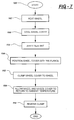
- Figure 7 is a flow chart of the steps of one embodiment of the inventive method.
-
- Referring to the Figures, a vehicle wheel assembly is generally indicated at 10. The
vehicle wheel assembly 10 includes awheel 12. Thewheel 12 includes anannular rim 14, arim flange 16 and arim flange protrusion 18. In the preferred embodiment shown in Figures 1 through 5, therim flange protrusion 18 extends downwardly from therim flange 16 generally perpendicularly thereto. - A
spider 20 is defined by therim flange 16. Thespider 20 is concentric with therim flange 16. Thespider 20 may be solid or, depending on design choices and cooling requirements, may include vent openings. Thespider 20 connects thevehicle wheel 12 to a wheel hub (not shown). Lug nuts (not shown) secure thewheel 12 to the wheel hub. - The
vehicle wheel assembly 10 further includes a wheel applique, generally indicated at 24. The wheel applique 24, i.e., a wheel cover, center cap or some other ornamentation defines aninboard surface 26, anoutboard surface 28 and aperiphery 30 disposed between the twosurfaces outboard surface 28 is treated with a coating for a desired look. The coating is an aesthetic coating and may include paint, chrome and the like. - The
inboard surface 26 is a utilitarian surface. It is not coated aesthetically as it is not visible once mounted to thevehicle wheel 12. Like theinboard surface 26, theperiphery 30 is not visible when thewheel applique 24 is mounted to thevehicle wheel 12. Therefore, it is not necessary for theperiphery 30 to be treated with an aesthetic coating and/or treatment. - The
wheel applique 24 includeslug nut openings 32. Thelug nut openings 32 provide access to the lug nuts should thewheel 12 be mounted or removed from the wheel hub. Like thespider 20 of thewheel 12, thewheel applique 24 may have openings between its axis and itsperiphery 30 for functional purposes, i.e., brake venting, or for aesthetic purposes. - The inventive method, shown in Figure 7, is the mounting of the wheel applique 24 to the
vehicle wheel 12. The method begins at 100 with providing thewheel 12 to which the wheel applique 24 is to be mounted. Thewheel applique 24 is then formed. Thewheel applique 24 is formed having a wheel applique diameter of a predetermined length. - The next step, 102, in the method is heating the
wheel 12 to a temperature allowing therim flange protrusion 18 to expand to a protrusion diameter greater than theperiphery 30 of the wheel applique 24. This step creates a temperature differential between thewheel 12 and thewheel applique 24. Thewheel 12 is heated to a temperature allowing the therim flange protrusion 18 to expand 50/1000ths of an inch. This increase in diameter for therim flange protrusion 18 is sufficient for the method to be performed. For such an expansion of thewheel 12 to occur, thewheel 12 is heated to approximately 250° F. - While the
wheel 12 is being heated, thewheel applique 24 may also be cooled at 104. This step will enhance the step of creating a temperature differential between thewheel 12 and thewheel applique 24. By way of example, to contract the diameter of thewheel applique 24 approximately 30/1000ths of an inch, thewheel applique 24 is cooled to 0° F, i.e., it is frozen. - Once the
wheel 12 is heated and, if desired, thewheel applique 24 is cooled, theinboard surface 26 of thewheel applique 24 is abutted against thespider 20 of thewheel 12 coaxially therewith at 106. More specifically, thewheel applique 24 is aligned with thewheel 12 while the difference in temperatures therebetween is the greatest. - The temperature differential is then removed by allowing the
vehicle wheel 12 to cool such that theoutboard surface 28 of thewheel applique 24 disposed adjacent theperiphery 30 abuts therim flange protrusion 18. When thewheel 12 is cooled at 108 and thewheel applique 24 warms to ambient temperature, the interference between theoutboard surface 28 and therim flange protrusion 18 is approximately 40/1000ths of an inch. This amount of interference is sufficient to lock thewheel applique 24 to thewheel 12. - A
sealant 34 is applied to either theinboard surface 26 of thewheel applique 24 or thespider 20 of thewheel 12 at 110. This step is performed before theinboard surface 26 is aligned with thespider 20. Once thesealant 34 is applied, thewheel applique 24 is abutted against thewheel 12 to seal the space defined thereby against contaminants found in the environment that may corrode thewheel 12 and/or thewheel applique 24. - In some environments of manufacture, a clamp may be required to secure the
wheel applique 24 to thewheel 12 before thewheel 12 and thewheel applique 24 return to ambient temperature. This step is performed at 112. Based on the temperatures identified above, a return to ambient temperature, along with a return of thewheel 12 and wheel applique 24 to normal dimensions, occurs within a short period of time from when thewheel 12 andwheel applique 24 are removed from their respective temperature conditioning devices. Finally, the clamp is removed at 114. - In an alternative embodiment, a different profile of a
wheel 36 is shown. Thiswheel 36 includes what is commonly referred to as a euro-flange 38. The euro-flange 38 includes arim extension 40 that extends generally in the same direction as thespider 42 thereof. The wheel applique 44 includes a hookedperiphery 46 in this embodiment. The hookedperiphery 46 abuts and covers therim extension 40 locking the wheel applique 44 to thewheel 36. - In this embodiment, the method still requires the differentiation of temperature but requires the heating of the wheel applique 44 allowing it to expand so that the hooked
periphery 46 may extend beyond the diameter of therim extension 40. Likewise, thewheel 36 is cooled to contract the diameter thereof to further aid in the hookedperiphery 46 passing over therim extension 40. Upon the return of thewheel 36 and wheel applique 44 to ambient temperature, eliminating the temperature differential, the hookedperiphery 46 positively contacts therim extension 40 locking the twoparts - The invention has been described in an illustrative manner. It is to be understood that the terminology which has been used is intended to be in the nature of words of description rather than of limitation.
- Many modifications and variations of the invention are possible in light of the above teachings. Therefore, within the scope of the appended claims, the invention may be practiced other than as specifically described.
Claims (14)
- A method of making a vehicle wheel assembly having an ornamental surface treatment, the method comprising the steps of:providing a vehicle wheel having an annular rim, a rim flange, a rim flange protrusion and a spider concentrically fixed within the rim for connecting the vehicle wheel to a rotating hub;forming a wheel applique having an inboard surface, an outboard surface and a periphery to be disposed adjacent the rim flange;creating a temperature differential between the vehicle wheel and the wheel applique allowing the rim flange protrusion to expand with respect to the periphery of the wheel applique;abutting the inboard surface of the wheel applique against the spider of the vehicle wheel coaxially therewith; andremoving the temperature differential between the vehicle wheel and the wheel applique such that the outboard surface of the wheel applique disposed adjacent the periphery abuts the rim flange protrusion locking the wheel applique to the vehicle wheel.
- A method according to claim 1 wherein the step of creating a temperature differential includes the step of heating the vehicle wheel.
- A method according to claim 1 or claim 2 including the step of cooling the wheel applique, (preferably during the step of heating the vehicle wheel) to reduce the diameter of the wheel applique.
- A method according to claim 3 further including the step of returning the wheel applique to ambient temperature during the step of cooling the vehicle wheel.
- A method according to any preceding claim further including applying a sealant to the spider of the vehicle wheel or the inboard surface of the wheel applique prior to the step of abutting.
- A method according to any preceding claim further including the step of clamping the wheel applique to the vehicle wheel while the temperature differential exists.
- A method of making a vehicle wheel assembly having an ornamental surface treatment, the method comprising the steps of:providing a vehicle wheel having an annular rim, a rim flange, a rim flange protrusion and a spider concentrically fixed within the rim for connecting the vehicle wheel to a rotating hub;forming a wheel applique having an inboard surface, an outboard surface and periphery to be disposed adjacent the rim flange;heating the vehicle wheel to a temperature allowing the rim flange protrusion to expand to a diameter greater than the periphery of the wheel applique;cooling the wheel applique during the step of heating the vehicle wheel to reduce the diameter of the wheel applique;abutting the inboard surface of the wheel applique against the spider of the vehicle wheel coaxially therewith; andreturning the vehicle wheel and the wheel applique to ambient temperature allowing the outboard surface of the wheel applique to abut the rim flange protrusion.
- A method according to claim 7 further including applying a sealant to the spider of the vehicle wheel or the inboard surface of the wheel applique prior to the step of abutting.
- A method according to claim 7 or claim 8 further including the step of clamping the wheel applique to the vehicle wheel while the vehicle wheel is cooled.
- A method of making a vehicle wheel assembly having an ornamental surface treatment, the method comprising the steps of:providing a vehicle wheel having an annular rim, a rim flange, a rim flange extension and a spider concentrically fixed within the rim for connecting the vehicle wheel to a rotating hub;forming a wheel applique having an inboard surface, an outboard surface and hooked periphery to cover the rim flange;cooling the vehicle wheel to a temperature allowing the rim flange protrusion to contract to a diameter less than the hooked periphery of the wheel applique;abutting the inboard surface of the wheel applique against the spider of the vehicle wheel coaxially therewith; andheating the vehicle wheel such that the outboard surface of the wheel applique disposed adjacent the rim flange extension abuts the hooked periphery of the wheel applique locking the wheel applique to the vehicle wheel.
- A method according to claim 10 further including the step of heating the wheel applique during the step of cooling the vehicle wheel to increase the diameter of the wheel applique.
- A method according to claim 11 further including the step of returning the wheel applique to ambient temperature during the step of heating the vehicle wheel.
- A method according to any of claims 10 to 12 further including applying a sealant to the spider of the vehicle wheel or the inboard surface of the wheel applique prior to the step of abutting.
- A method according to claim 12 further including the step of clamping the wheel applique to the vehicle wheel while the vehicle wheel is heated.
Applications Claiming Priority (2)
| Application Number | Priority Date | Filing Date | Title |
|---|---|---|---|
| US658438 | 2000-09-08 | ||
| US09/658,438 US6209204B1 (en) | 2000-09-08 | 2000-09-08 | Method for securing a wheel applique to a wheel |
Publications (2)
| Publication Number | Publication Date |
|---|---|
| EP1186443A2 true EP1186443A2 (en) | 2002-03-13 |
| EP1186443A3 EP1186443A3 (en) | 2003-10-29 |
Family
ID=24641248
Family Applications (1)
| Application Number | Title | Priority Date | Filing Date |
|---|---|---|---|
| EP01306029A Withdrawn EP1186443A3 (en) | 2000-09-08 | 2001-07-12 | Method for securing a wheel applique to a wheel |
Country Status (2)
| Country | Link |
|---|---|
| US (1) | US6209204B1 (en) |
| EP (1) | EP1186443A3 (en) |
Families Citing this family (14)
| Publication number | Priority date | Publication date | Assignee | Title |
|---|---|---|---|---|
| US6779852B2 (en) * | 2001-04-19 | 2004-08-24 | Lacks Industries, Inc. | Composite wheel assembly and method for producing same |
| BR0103968A (en) * | 2001-08-20 | 2003-08-05 | Meritor Do Brasil Ltda Divisao | Wheel and casing |
| US6637832B2 (en) * | 2001-10-10 | 2003-10-28 | Lacks Enterprises, Inc. | Wheel and cladding |
| US20030165664A1 (en) * | 2002-03-01 | 2003-09-04 | Oakwood Custom Coating, Inc. | Method of making a composite panel and article made thereby |
| US7204562B2 (en) | 2002-10-23 | 2007-04-17 | Lacks Enterprises, Inc. | Wheel clad assembly |
| US6969124B2 (en) * | 2002-11-19 | 2005-11-29 | Lacks Enterprises, Inc. | Center cap for vehicle wheel |
| US6932435B2 (en) * | 2003-11-07 | 2005-08-23 | Mckechnie Vehicle Components (Usa), Inc. | Adhesive patterns for vehicle wheel assemblies |
| US6991299B2 (en) * | 2004-02-18 | 2006-01-31 | Lacks Enterprises, Inc. | Vehicle wheel assembly and cladding therefore |
| WO2008010835A1 (en) * | 2005-12-08 | 2008-01-24 | Hayes Lemmerz International, Inc. | Fabricated vehicle wheel and method for producing same |
| US20080001468A1 (en) * | 2006-06-26 | 2008-01-03 | Hauler Gregory R | Multiple Clad Wheel Assembly |
| US8074946B2 (en) * | 2008-12-30 | 2011-12-13 | Robert Bosch Gmbh | Hose hanger assembly having car wheel rim configuration with removable cover structure |
| DE102013003690A1 (en) * | 2013-03-04 | 2014-09-04 | Bayerische Motoren Werke Aktiengesellschaft | rim assembly |
| DE102013003699B4 (en) * | 2013-03-04 | 2024-04-25 | Bayerische Motoren Werke Aktiengesellschaft | Rim assembly and method for assembling a rim assembly |
| US9707800B2 (en) | 2013-03-15 | 2017-07-18 | Lacks Enterprises, Inc. | Partial wheel cladding |
Citations (4)
| Publication number | Priority date | Publication date | Assignee | Title |
|---|---|---|---|---|
| US3726566A (en) | 1970-01-02 | 1973-04-10 | Et Ind | Wheel structure |
| DE2813412A1 (en) | 1978-03-29 | 1979-10-04 | Porsche Ag | Trim cover for aluminium alloy vehicle wheel - has clip on panels covered with protective layer |
| US5368370A (en) | 1993-09-03 | 1994-11-29 | Thompson International | Vehicle wheel construction |
| US5597213A (en) | 1995-06-06 | 1997-01-28 | Lacks Industries, Inc. | Wheel and overlay assembly |
Family Cites Families (6)
| Publication number | Priority date | Publication date | Assignee | Title |
|---|---|---|---|---|
| US3397921A (en) * | 1968-02-06 | 1968-08-20 | Gar Wood Ind Inc | Vehicle wheel trim |
| US4316637A (en) * | 1978-08-04 | 1982-02-23 | Reynolds Metals Company | Multi-styled aluminum wheel |
| US4530542A (en) * | 1983-06-29 | 1985-07-23 | Mr. Gasket Company | Non-ferrous wheel center with chromed steel cover |
| US5664845A (en) * | 1994-02-28 | 1997-09-09 | Hayes Wheels International, Inc | Vehicle wheel cover retention system and method for producing same |
| US5921634A (en) * | 1997-05-27 | 1999-07-13 | Mckechnie Vehicle Components (Usa), Inc. | Wheel applique and lock |
| CA2272152A1 (en) * | 1998-05-22 | 1999-11-22 | Mckechnie Vehicle Components (Usa), Inc. | Wheel cover assembly |
-
2000
- 2000-09-08 US US09/658,438 patent/US6209204B1/en not_active Expired - Fee Related
-
2001
- 2001-07-12 EP EP01306029A patent/EP1186443A3/en not_active Withdrawn
Patent Citations (4)
| Publication number | Priority date | Publication date | Assignee | Title |
|---|---|---|---|---|
| US3726566A (en) | 1970-01-02 | 1973-04-10 | Et Ind | Wheel structure |
| DE2813412A1 (en) | 1978-03-29 | 1979-10-04 | Porsche Ag | Trim cover for aluminium alloy vehicle wheel - has clip on panels covered with protective layer |
| US5368370A (en) | 1993-09-03 | 1994-11-29 | Thompson International | Vehicle wheel construction |
| US5597213A (en) | 1995-06-06 | 1997-01-28 | Lacks Industries, Inc. | Wheel and overlay assembly |
Also Published As
| Publication number | Publication date |
|---|---|
| EP1186443A3 (en) | 2003-10-29 |
| US6209204B1 (en) | 2001-04-03 |
Similar Documents
| Publication | Publication Date | Title |
|---|---|---|
| US6209204B1 (en) | Method for securing a wheel applique to a wheel | |
| AU726615B2 (en) | Wheel applique and lock | |
| EP0785875B1 (en) | Vehicle wheel construction | |
| US6035978A (en) | Brake Disk | |
| US7416260B1 (en) | Vehicle wheel cover retention system and method for producing same | |
| US20020153763A1 (en) | Composite wheel assembly and method for producing same | |
| US6637832B2 (en) | Wheel and cladding | |
| US5595423A (en) | Vehicle wheel cover retention system and method for producing same | |
| US6502308B1 (en) | Vehicle wheel cover retention system and method for producing same | |
| US4457560A (en) | Hubcap with improved retention structure | |
| US20070278850A1 (en) | Wheel and wheel disk | |
| US6270167B1 (en) | Vehicle wheel cover retention system and method for producing same | |
| US7494192B2 (en) | Vehicle wheel rim flange and overlay assembly | |
| WO1999062727A2 (en) | Fastener structure | |
| US5921634A (en) | Wheel applique and lock | |
| EP0956977B1 (en) | Mechanical locks for wheel covers | |
| US6036280A (en) | Two piece vehicle wheel with press fit rim | |
| US5975647A (en) | Wheel hub unit | |
| JPH021681B2 (en) | ||
| US7448695B1 (en) | Vehicle wheel cover retention system and method for producing same | |
| GB2403696A (en) | Wheel protector device | |
| US8845035B2 (en) | Vehicle wheel cover and vehicle wheel cover retention system and method for producing same | |
| US12434505B2 (en) | Motor-vehicle wheel-rim protector | |
| US20060087172A1 (en) | Wheel cover assembly and method | |
| US20030221759A1 (en) | Multi-piece rim for pneumatic tire |
Legal Events
| Date | Code | Title | Description |
|---|---|---|---|
| PUAI | Public reference made under article 153(3) epc to a published international application that has entered the european phase |
Free format text: ORIGINAL CODE: 0009012 |
|
| AK | Designated contracting states |
Kind code of ref document: A2 Designated state(s): AT BE CH CY DE DK ES FI FR GB GR IE IT LI LU MC NL PT SE TR |
|
| AX | Request for extension of the european patent |
Free format text: AL;LT;LV;MK;RO;SI |
|
| PUAL | Search report despatched |
Free format text: ORIGINAL CODE: 0009013 |
|
| AK | Designated contracting states |
Kind code of ref document: A3 Designated state(s): AT BE CH CY DE DK ES FI FR GB GR IE IT LI LU MC NL PT SE TR |
|
| AX | Request for extension of the european patent |
Extension state: AL LT LV MK RO SI |
|
| AKX | Designation fees paid | ||
| REG | Reference to a national code |
Ref country code: DE Ref legal event code: 8566 |
|
| STAA | Information on the status of an ep patent application or granted ep patent |
Free format text: STATUS: THE APPLICATION IS DEEMED TO BE WITHDRAWN |
|
| 18D | Application deemed to be withdrawn |
Effective date: 20040430 |