EP1186402A2 - Method and apparatus for forming carved grooves on green tires - Google Patents
Method and apparatus for forming carved grooves on green tires Download PDFInfo
- Publication number
- EP1186402A2 EP1186402A2 EP01307496A EP01307496A EP1186402A2 EP 1186402 A2 EP1186402 A2 EP 1186402A2 EP 01307496 A EP01307496 A EP 01307496A EP 01307496 A EP01307496 A EP 01307496A EP 1186402 A2 EP1186402 A2 EP 1186402A2
- Authority
- EP
- European Patent Office
- Prior art keywords
- green tire
- carved
- cutter
- circumferential surface
- moving means
- Prior art date
- Legal status (The legal status is an assumption and is not a legal conclusion. Google has not performed a legal analysis and makes no representation as to the accuracy of the status listed.)
- Granted
Links
- 238000000034 method Methods 0.000 title claims abstract description 8
- 238000005259 measurement Methods 0.000 claims description 2
- 238000010586 diagram Methods 0.000 description 2
- 238000010276 construction Methods 0.000 description 1
- 238000004519 manufacturing process Methods 0.000 description 1
- 238000002844 melting Methods 0.000 description 1
- 230000008018 melting Effects 0.000 description 1
Images



Classifications
-
- B—PERFORMING OPERATIONS; TRANSPORTING
- B29—WORKING OF PLASTICS; WORKING OF SUBSTANCES IN A PLASTIC STATE IN GENERAL
- B29D—PRODUCING PARTICULAR ARTICLES FROM PLASTICS OR FROM SUBSTANCES IN A PLASTIC STATE
- B29D30/00—Producing pneumatic or solid tyres or parts thereof
- B29D30/06—Pneumatic tyres or parts thereof (e.g. produced by casting, moulding, compression moulding, injection moulding, centrifugal casting)
- B29D30/52—Unvulcanised treads, e.g. on used tyres; Retreading
- B29D30/68—Cutting profiles into the treads of tyres
-
- B—PERFORMING OPERATIONS; TRANSPORTING
- B29—WORKING OF PLASTICS; WORKING OF SUBSTANCES IN A PLASTIC STATE IN GENERAL
- B29D—PRODUCING PARTICULAR ARTICLES FROM PLASTICS OR FROM SUBSTANCES IN A PLASTIC STATE
- B29D30/00—Producing pneumatic or solid tyres or parts thereof
- B29D30/06—Pneumatic tyres or parts thereof (e.g. produced by casting, moulding, compression moulding, injection moulding, centrifugal casting)
- B29D30/52—Unvulcanised treads, e.g. on used tyres; Retreading
- B29D30/68—Cutting profiles into the treads of tyres
- B29D2030/685—Cutting profiles into the treads of tyres before tread vulcanization
-
- Y—GENERAL TAGGING OF NEW TECHNOLOGICAL DEVELOPMENTS; GENERAL TAGGING OF CROSS-SECTIONAL TECHNOLOGIES SPANNING OVER SEVERAL SECTIONS OF THE IPC; TECHNICAL SUBJECTS COVERED BY FORMER USPC CROSS-REFERENCE ART COLLECTIONS [XRACs] AND DIGESTS
- Y10—TECHNICAL SUBJECTS COVERED BY FORMER USPC
- Y10T—TECHNICAL SUBJECTS COVERED BY FORMER US CLASSIFICATION
- Y10T83/00—Cutting
- Y10T83/02—Other than completely through work thickness
- Y10T83/0304—Grooving
-
- Y—GENERAL TAGGING OF NEW TECHNOLOGICAL DEVELOPMENTS; GENERAL TAGGING OF CROSS-SECTIONAL TECHNOLOGIES SPANNING OVER SEVERAL SECTIONS OF THE IPC; TECHNICAL SUBJECTS COVERED BY FORMER USPC CROSS-REFERENCE ART COLLECTIONS [XRACs] AND DIGESTS
- Y10—TECHNICAL SUBJECTS COVERED BY FORMER USPC
- Y10T—TECHNICAL SUBJECTS COVERED BY FORMER US CLASSIFICATION
- Y10T83/00—Cutting
- Y10T83/04—Processes
-
- Y—GENERAL TAGGING OF NEW TECHNOLOGICAL DEVELOPMENTS; GENERAL TAGGING OF CROSS-SECTIONAL TECHNOLOGIES SPANNING OVER SEVERAL SECTIONS OF THE IPC; TECHNICAL SUBJECTS COVERED BY FORMER USPC CROSS-REFERENCE ART COLLECTIONS [XRACs] AND DIGESTS
- Y10—TECHNICAL SUBJECTS COVERED BY FORMER USPC
- Y10T—TECHNICAL SUBJECTS COVERED BY FORMER US CLASSIFICATION
- Y10T83/00—Cutting
- Y10T83/162—With control means responsive to replaceable or selectable information program
- Y10T83/173—Arithmetically determined program
-
- Y—GENERAL TAGGING OF NEW TECHNOLOGICAL DEVELOPMENTS; GENERAL TAGGING OF CROSS-SECTIONAL TECHNOLOGIES SPANNING OVER SEVERAL SECTIONS OF THE IPC; TECHNICAL SUBJECTS COVERED BY FORMER USPC CROSS-REFERENCE ART COLLECTIONS [XRACs] AND DIGESTS
- Y10—TECHNICAL SUBJECTS COVERED BY FORMER USPC
- Y10T—TECHNICAL SUBJECTS COVERED BY FORMER US CLASSIFICATION
- Y10T83/00—Cutting
- Y10T83/525—Operation controlled by detector means responsive to work
- Y10T83/538—Positioning of tool controlled
-
- Y—GENERAL TAGGING OF NEW TECHNOLOGICAL DEVELOPMENTS; GENERAL TAGGING OF CROSS-SECTIONAL TECHNOLOGIES SPANNING OVER SEVERAL SECTIONS OF THE IPC; TECHNICAL SUBJECTS COVERED BY FORMER USPC CROSS-REFERENCE ART COLLECTIONS [XRACs] AND DIGESTS
- Y10—TECHNICAL SUBJECTS COVERED BY FORMER USPC
- Y10T—TECHNICAL SUBJECTS COVERED BY FORMER US CLASSIFICATION
- Y10T83/00—Cutting
- Y10T83/647—With means to convey work relative to tool station
- Y10T83/6667—Work carrier rotates about axis fixed relative to tool station
Definitions
- the present invention relates to a method and an apparatus for forming a carved groove for a lug groove with a cutter on an outer circumferential surface of a green tire before curing.
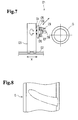
- Fig. 7 shows a conventional carved groove forming apparatus 01 used for carving a carved groove for a lug groove with a cutter on an outer circumferential surface of a green tire.
- a green tire G has a central axis supported horizontally.
- the carved groove forming apparatus 01 has a base stand 03 laid on a rail 02 so as to move toward the green tire perpendicularly to the central axis of the green tire G and horizontally (in direction X).
- the base stand 03 has a rotary shaft 04 projected in direction X toward the green tire G.
- the rotary shaft 04 is provided with a rotary disk 05 integrally.
- the rotary disk 05 has a pair of rails 06 along which a slide disk 07 slides.
- the slide disk 07 has a cutter 08 and a photo-sensor 09.
- the cutter 08 stands up and falls down relatively to the slide disk according to action of an air cylinder. Carving of the green tire G by the carved groove forming apparatus 01 is carried out as follows.
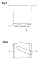
- outer circumference of the green tire G is partitioned off into 36 portions, and in each portion as shown in Fig. 8, a cut shape (shown by one-dot-dash line in Fig. 8) is described on the outer circumferential surface of the green tire by marking-off.
- the photo-sensor 09 detects cut starting point A and measures distance
- the base stand 03 is moved in the direction X so that the fallen cutter 08 positions at a place distant from the green tire G by a predetermined distance
- the rotary shaft 04 and the rotary disk 05 are rotated together by hand to set direction of the rail 09 so that the cutter 08 moves in direction of angle of marking-off of the cut shape.
- the cutter 08 is revolved to stand up by the air cylinder, and eats into the green tire G by a predetermined depth at the cut starting point A as shown in Fig. 9.
- slide disk is moved together with the cutter 08 along the rail 02 by hand to form the carved groove.
- the distance from the central axis to the outer circumferential surface of the green tire is called the outer diameter.
- Fig. 9 shows a state of the green tire G in which outer diameters vary largely in particular.
- the cutter 08 is moved in parallel with the central axis C-C' of the green tire G, a carved groove of uneven depth as shown by the broken line is formed, and the uneven depth remains as it is when the green tire is deformed into a state near a true circle by the above-mentioned inner pressure. Therefore, shape of the lug groove rib and shape of the carved groove are different from each other largely, so that an accurate lug groove can not be formed.
- the portion to be carved of the green tire is carved to a necessary depth only at the cut starting point A, and another part of the portion to be carved can not be carved to the necessary depth because the depth is influenced by variation of the outer diameters.
- the present invention has been accomplished in view of the foregoing, and an object of the invention is to provide a method and an apparatus for forming a carved groove of a green tire capable of forming a carved groove of a necessary depth without being influenced by variation of outer diameters of the green tire.
- the present invention provides a method for forming a carved groove for a lug groove with a cutter on an outer circumferential surface of a green tire before curing, comprising: moving a distance sensor along a portion to be carved on the outer circumferential surface of the green tire to measure outer diameters of the portion to be carved; revising cut shape data for a green tire having an ideal shape stored in memory beforehand on the basis of the measured outer diameters; and moving the cutter in accordance with the revised cut shape data for carving.
- the cut shape data for a green tire having an ideal shape is revised on the basis of the measured outer diameters, and carving is carried out in accordance with the revised cut shape data, even if outer diameters of the green tire vary, a carved groove having necessary depths is formed on the green tire.
- the carved groove becomes the necessary shape similar to the shape of the lug groove rib, so that the lug groove rib enters the carved groove properly and an accurate lug groove is formed.
- Measurement of the outer diameters of the portion to be carved may comprise moving the distance sensor to detect distances to the outer circumferential surface of the green tire at plural points continuously or intermittently, and subtracting the detected distances from the distance between the distance sensor and a central axis of the green tire to calculate outer diameters of the portion to be carved at plural points.
- the cut shape data stored beforehand may be revised on the basis of difference between the measured outer diameter of the green tire and an outer diameter of a green tire having an ideal shape.
- the present invention provides an apparatus for forming a carved groove for a lug groove on an outer circumferential surface of a green tire before curing, comprising: a cutter for carving the outer circumferential surface of the green tire to form the carved groove; a cutter moving means for moving the cutter; a distance sensor for detecting distance to the outer circumferential surface of the green tire; a sensor moving means for moving the distance sensor; and a control means for storing cut shape data for a green tire having an ideal shape and controlling the cutter moving means and the sensor moving means, the control means controlling the sensor moving means so that the distance sensor moves along a portion to be carved on the outer circumferential surface of the green tire to measure outer diameters of the portion to be carved, revising the cut shape data stored beforehand on the basis of the measured outer diameter of the portion to be carved, controlling the cutter moving means in accordance with the revised cut shape data so that the cutter carves a necessary place of the outer circumferential surface of the green tire to form the carved groove.
- control means measures the outer diameter of the portion to be carved, revises the cut shape data and moves the cutter to carve a necessary place of outer circumferential surface of the green tire, compared with a case that the cutter is operated manually to carve the green tire, a carved groove having necessary depths can be formed accurately, efficiently and automatically.
- the cutter and the distance sensor may be fixed to a same support member, and the cutter moving means and the sensor moving means may be constituted by a common moving means.
- the apparatus can be simplified and cost can be reduced.
- the common moving means may be a multi-joint robot.
- Position, attitude and moving direction of the cutter can be set accurately and freely so that a proper carved groove can be formed on the green tire.
- the multi-joint robot may have degree of freedom of six axes.
- the cutter can be supported taking an attitude most suitable for carving of the green tire so that a carved groove having necessary depths can be formed accurately.
- the distance sensor may be a reflective photo-sensor.
- the carved groove forming apparatus 1 according to the embodiment shown in Fig. 1 relates to manufacturing of ORR (off the road radial) tire of a large-sized vehicle for construction.
- the carved groove forming apparatus 1 comprises a multi-joint robot 3 capable of manipulating a cutter 2 freely and a support stand for supporting a green tire G so as to rotate, and the multi-joint robot 3 and the support stand 10 are arranged face to face apart from each other by a predetermined distance.
- the multi-joint robot 3 has degree of freedom of six axes.
- a rotary base stand 4 is provided on a floor so as to rotate about a vertical axis S horizontally (S-rotation), a first arm 5 extending upward is connected to the rotary base stand 4 so as to swing about a horizontal axis L before and after (L-swing), and a second arm 6 extending forward is connected to an upper end of the first arm 5 so as to swing about a horizontal axis U up and down (U-swing).
- the second arm 6 rotates about the arm center axis R (R-rotation).
- a third arm 7 is connected to a tip end of the second arm 6 so as to swing about an axis B right-angled to the arm center axis R (B-swing).
- the cutter 2 is projected at a tip end of the third arm 7 so as to rotate about the arm center axis T (T-rotation).
- a photo-sensor 8 which rotates about the axis T together with the cutter 2 (Fig. 2).
- the cutter 2 is a terminal end of the multi-joint robot 3 having degree of freedom of six axes (S-rotation, L-swing, U-swing, R-rotation, B-swing and T-rotation).
- the cutter 2 is a electric heated cutter having an edge curved in U-shape and carves the green tire melting it.
- the green tire is supported by a rim 15 having a central shaft 16 projected horizontally on both sides.
- the shaft 16 is supported on a support stand through a pair of bearing rollers 11.
- Fig. 2 shows a brief block diagram of the control system.
- the control apparatus 20 outputs an instruction signal to a roller driving means 21 which drives the bearing rollers 11 of the support stand 10 to rotate the green tire.
- the control apparatus 20 outputs an instruction signal to a robot driving means 22 which drives the multi-joint robot 3 to move the cutter 3 for carving work.
- control apparatus 20 outputs a signal to the photo-sensor 8.
- the photo-sensor 8 projects a light which is reflected by a reflective surface as a reflective light.
- a signal indicating the reflective light is received by the control apparatus for calculating distance between the photo-sensor 8 and the reflective surface.
- the control apparatus 20 has a memory 20a in which cut shape data for a green tire having an ideal shape are stored beforehand regarding every kind of tires.
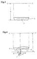
- Fig. 3 shows a section of a tread portion of a green tire having an ideal shape of even outer diameters.
- the green tire G of ideal shape has predetermined constant outer diameters (distance from the center axis to the outer circumferential surface) r 0 .
- the one-dot-dash line L1 of Fig. 3 shows a shape of a carved groove corresponding to the cut shape data in such a green tire G.
- the multi-joint robot 3 is controlled in accordance with the stored, not revised cut shape data and the cutter 2 is moved along the one-dot-dash line L1 of Fig. 3 to form a carved groove of necessary shape as shown by the one-dot-dash line L1.
- the outer diameters r are varied and not constant as shown in fig. 4. Therefore, firstly the outer diameters are measured by the photo-sensor 8.
- the multi-joint robot 3 is controlled so that the photo-sensor 8 moves along the portion to be carved on the outer circumferential surface of the green tire G keeping a nearly constant distance a from the center axis C-C', projected light is reflected at the surface of the portion to be carved and the reflected light is received, and distances d to the surface of the portion to be carved is measured based on the received signals at plural points.
- the multi-joint robot 3 is controlled on the basis of the revised cut shape data to move the cutter 2 for carving, and the carved groove shown by the two-dots-dash line L2 in Fig. 4 is formed.
- the green tire G on the support stand 10 is rotated intermittently by a constant rotational angle, and when the green tire G is stopped, the photo-sensor 8 scans the portion to be carved to measure the outer diameters r, the cut shape data is revised and the cutter 2 is driven by the multi-joint robot 3 in accordance with the revised cut shape data to form the carved groove.
- a plurality of carved grooves g of necessary depths arranged in circumferential direction can be formed.
- the shape of the carved groove g becomes about the same as the shape corresponding to the cut shape data for a green tire having an ideal shape.
- the lug groove ribs of the mold of a curing machine enter properly in the carved grooves g having necessary depths and shapes to form lug grooves accurately.
- a carved groove having necessary depths can be formed easily without being influenced by variation of outer diameters of the green tire.
- the cutter 2 Since the cutter 2 is moved by the multi-joint robot 3 having degree of freedom of six axes, positioning of the cutter can be automated, the edge of the cutter 2 can be set at any position accurately and the edge can be kept always perpendicularly to the curved surface of the green tire G to carve accurately.
- the portion to be carved is carved in accordance with the revised cut shape data, the carved groove g having necessary depths from the surface of the portion to be carved and a necessary shape is formed. Therefore, cut weight at every portion to be carved can be kept uniformly and accuracy of the cut weight is stabilized, so that variation of tread gauge and groove bottom skid base gauge of the product tire can be suppressed to the minimum and quality of the product tire can be maintained.
Landscapes
- Engineering & Computer Science (AREA)
- Mechanical Engineering (AREA)
- Tyre Moulding (AREA)
- Moulds For Moulding Plastics Or The Like (AREA)
- Length Measuring Devices With Unspecified Measuring Means (AREA)
Abstract
Description
Claims (8)
- A method for forming a carved groove (g) for a lug groove with a cutter (2) on an outer circumferential surface of a green tire (G) before curing, comprising:moving a distance sensor (8) along a portion to be carved on said outer circumferential surface of said green tire to measure outer diameters of said portion to be carved;revising cut shape data for a green tire having an ideal shape, stored in memory beforehand; andmoving said cutter in accordance with revised cut shape data for carving.
- A method as claimed in claim 1, characterized in that measurement of said outer diameters of said portion to be carved comprises moving said distance sensor (8) to detect distances of said outer circumferential surface of said green tire (G) at plural points, and subtracting said detected distances from a distance between said distance sensor and a central axis of said green tire to calculate outer diameters of said portion to be carved at plural points.
- A method as claimed in claim 1 or 2, characterized in that said cut shape data stored beforehand is revised on the basis of difference between said measured outer diameter of said green tire (G) and an outer diameter of a green tire having an ideal shape.
- Apparatus (1) for forming a carved groove (g) for a lug groove on an outer circumferential surface of a green tire (G) before curing, comprising:a cutter (2) for carving said outer circumferential surface of said green tire to form said carved groove;a cutter moving means for moving said cutter;a distance sensor (8) for detecting distance to said outer circumferential surface of said green tire;a sensor moving means for moving said distance sensor; anda control means (20) for storing cut shape data for a green tire having an ideal shape and controlling said cutter moving means and said sensor moving means,said control means controlling said sensor moving means so that said distance sensor moves along a portion to be carved on said outer circumferential surface of said green tire to measure outer diameters of said portion to be carved, revising said cut shape data stored beforehand on the basis of said measured outer diameters of said portion to be carved, and controlling said cutter moving means in accordance with said revised cut shape data so that said cutter carves a necessary place of said outer circumferential surface of said green tire to form said carved groove.
- Apparatus as claimed in claim 4, characterized in that said cutter (2) and said distance sensor (8) are fixed to a same support member, and said cutter moving means and said sensor moving means are constituted by a common moving means (3).
- Apparatus as claimed in claim 5, characterized in that said common moving means is a multi-joint robot (3).
- Apparatus as claimed in claim 6, characterized in that said multi-joint robot (3) has degree of freedom of six axes.
- Apparatus as claimed in any of claims 4 to 7, characterized in that said distance sensor is a reflective photo-sensor (8).
Applications Claiming Priority (2)
| Application Number | Priority Date | Filing Date | Title |
|---|---|---|---|
| JP2000271006 | 2000-09-07 | ||
| JP2000271006A JP4726286B2 (en) | 2000-09-07 | 2000-09-07 | Raw tire excavation groove forming method and apparatus |
Publications (3)
| Publication Number | Publication Date |
|---|---|
| EP1186402A2 true EP1186402A2 (en) | 2002-03-13 |
| EP1186402A3 EP1186402A3 (en) | 2003-10-01 |
| EP1186402B1 EP1186402B1 (en) | 2005-06-15 |
Family
ID=18757352
Family Applications (1)
| Application Number | Title | Priority Date | Filing Date |
|---|---|---|---|
| EP01307496A Expired - Lifetime EP1186402B1 (en) | 2000-09-07 | 2001-09-04 | Method and apparatus for forming carved grooves on green tires |
Country Status (5)
| Country | Link |
|---|---|
| US (1) | US6951235B2 (en) |
| EP (1) | EP1186402B1 (en) |
| JP (1) | JP4726286B2 (en) |
| DE (1) | DE60111466T2 (en) |
| ES (1) | ES2242711T3 (en) |
Cited By (3)
| Publication number | Priority date | Publication date | Assignee | Title |
|---|---|---|---|---|
| FR2896720A1 (en) * | 2006-01-27 | 2007-08-03 | P S O Pneu Service Outil Soc P | Apparatus for cutting grooves in a tire tread, especially for retreading, comprises a measuring device for determining the optimum groove depth |
| ITMI20130611A1 (en) * | 2013-04-15 | 2014-10-16 | Leonardo Cappuccini | MACHINE TO SCRAP THE TREAD OF RECONSTRUCTED TIRES. |
| EP2637827A4 (en) * | 2010-11-11 | 2018-01-24 | Thomas, Hughen Gerrard | Method for enhancing reach of a robotic arm |
Families Citing this family (20)
| Publication number | Priority date | Publication date | Assignee | Title |
|---|---|---|---|---|
| JP4702982B2 (en) * | 1999-08-04 | 2011-06-15 | 株式会社ブリヂストン | Pneumatic tire manufacturing equipment |
| US20070261528A1 (en) * | 2003-11-06 | 2007-11-15 | Sarmasik Makine Sanayi Ve Ticaret A.S. | Unit Cutting Dough Surface in Equal Depth |
| JP2007216829A (en) * | 2006-02-16 | 2007-08-30 | Bridgestone Corp | Tire for construction vehicle, and its manufacturing method |
| US7975579B1 (en) * | 2007-04-24 | 2011-07-12 | Eagle International, Llc | System and method for cutting tires |
| BRPI0822592B1 (en) * | 2008-04-18 | 2021-02-02 | Pirelli Tyre S.P.A. | tire fitting process and apparatus |
| JP5408776B2 (en) * | 2009-08-24 | 2014-02-05 | 株式会社ブリヂストン | Tire and tire component manufacturing apparatus and method |
| WO2012057742A1 (en) | 2010-10-27 | 2012-05-03 | Michelin Recherche Et Technique, S.A. | A tire tread with sipes and a method for the manufacture of a tire tread with sipes |
| WO2012154718A1 (en) * | 2011-05-09 | 2012-11-15 | Drexel University | Semi-autonomous rescue apparatus |
| US9616716B2 (en) | 2011-12-14 | 2017-04-11 | Bridgestone Americas Tire Operations, Llc | Three dimensional sipe |
| US9144916B2 (en) * | 2012-02-10 | 2015-09-29 | Eagle International, Llc | System and method of removing beads from tires |
| US8621968B1 (en) * | 2012-11-16 | 2014-01-07 | Eagle International, Inc. | Tire shearing apparatus |
| JP5831592B2 (en) * | 2014-05-09 | 2015-12-09 | 横浜ゴム株式会社 | Tire trimming apparatus and method |
| CN106625831A (en) * | 2015-10-31 | 2017-05-10 | 重庆互通管道技术设备有限公司 | Folding winding pipe internal cutting device |
| CN109130654A (en) * | 2018-09-06 | 2019-01-04 | 安徽佳通乘用子午线轮胎有限公司 | A kind of semi-automatic tyre tread engraving tooling |
| CN111409299B (en) * | 2020-04-23 | 2022-07-19 | 刘波 | Automobile tire processing method |
| CN112060169A (en) * | 2020-09-02 | 2020-12-11 | 李杨 | Tire processing device and method |
| KR102401472B1 (en) * | 2020-10-16 | 2022-05-25 | 금호타이어 주식회사 | Repair Apparatus for Green Case |
| US20230182341A1 (en) * | 2021-12-09 | 2023-06-15 | Ecofortune Renewable Energy Co., Ltd. | Water jet splitting machine for waste tires |
| CN115091595B (en) * | 2022-06-22 | 2024-06-07 | 苏州隐冠半导体技术有限公司 | Preparation method and preparation system of ceramic green body |
| CN116872542A (en) * | 2023-07-07 | 2023-10-13 | 三角(威海)华盛轮胎有限公司 | Process method for forming tire pattern groove device |
Family Cites Families (24)
| Publication number | Priority date | Publication date | Assignee | Title |
|---|---|---|---|---|
| US1521238A (en) * | 1922-09-30 | 1924-12-30 | Goodrich Co B F | Grooving machine |
| US3502131A (en) * | 1967-03-14 | 1970-03-24 | Nat Standard Co | Apparatus for cutting tread patterns in built-up tires |
| FR1572177A (en) * | 1967-11-29 | 1969-06-27 | ||
| US4081017A (en) * | 1976-09-27 | 1978-03-28 | The Goodyear Tire & Rubber Company | Apparatus for grooving tires |
| US4206798A (en) * | 1978-06-16 | 1980-06-10 | The Goodyear Tire & Rubber Company | Apparatus for forming traction grooves in the uncured tread of a heavy off-highway tire and method therefore |
| US4782881A (en) * | 1980-04-16 | 1988-11-08 | The Goodyear Tire & Rubber Company | Method and apparatus for grooving tire tread |
| DE3162730D1 (en) * | 1980-04-16 | 1984-04-26 | Goodyear Tire & Rubber | Method and apparatus for grooving tire tread |
| BE894644A (en) * | 1982-10-08 | 1983-04-08 | Bekaert Sa Nv | METHOD AND APPARATUS FOR MANUFACTURING THE TIRE OF A TIRE |
| JPS59215849A (en) * | 1983-05-24 | 1984-12-05 | Sumitomo Rubber Ind Ltd | Grooving method of tire |
| US4668456A (en) * | 1984-03-07 | 1987-05-26 | The Uniroyal Goodrich Tire Company | Reduced flash molding |
| JPS60212336A (en) * | 1984-04-09 | 1985-10-24 | Bridgestone Corp | Method and apparatus for manufacturing high-lug tire |
| JPS61177232A (en) * | 1985-02-04 | 1986-08-08 | Sumitomo Rubber Ind Ltd | Grooving device of tire |
| JPH07115427B2 (en) * | 1986-10-09 | 1995-12-13 | 株式会社ブリヂストン | Tire shaving device |
| JPH01130921A (en) * | 1987-11-17 | 1989-05-23 | Bridgestone Corp | Manufacture of pneumatic tire |
| AU606487B2 (en) * | 1987-12-19 | 1991-02-07 | Sumitomo Rubber Industries, Ltd. | Method for correcting tyre deflection in tyre grooving and apparatus therefor |
| JPH01163052A (en) * | 1987-12-19 | 1989-06-27 | Sumitomo Rubber Ind Ltd | Cutter support device of grooving apparatus |
| JPH01301233A (en) * | 1988-05-30 | 1989-12-05 | Sumitomo Rubber Ind Ltd | Method and apparatus for correcting vertical vibration of tire grooving |
| EP0372090B1 (en) * | 1988-06-10 | 1994-03-30 | Sumitomo Rubber Industries Limited | Tire grooving apparatus |
| US5193600A (en) * | 1988-07-28 | 1993-03-16 | Sumitomo Rubber Industries, Ltd. | Tire grooving apparatus and method |
| JPH04341835A (en) * | 1991-05-17 | 1992-11-27 | Bridgestone Corp | Skiving apparatus for reclaimed tire |
| US5179782A (en) * | 1991-12-23 | 1993-01-19 | Alstine Guy A Van | Tire groover cutting head member having fixed insulator |
| IT1273333B (en) * | 1994-02-24 | 1997-07-08 | Pirelli | METHOD AND EQUIPMENT FOR THE TRACKING OF A FOOTPRINT DRAWING ON THE TIRE BAND OF A TIRE |
| DE19642283A1 (en) * | 1996-10-14 | 1998-04-16 | Timothy Grime | Advanced method of cutting tyre tread into green blank |
| JP4702982B2 (en) * | 1999-08-04 | 2011-06-15 | 株式会社ブリヂストン | Pneumatic tire manufacturing equipment |
-
2000
- 2000-09-07 JP JP2000271006A patent/JP4726286B2/en not_active Expired - Lifetime
-
2001
- 2001-09-04 ES ES01307496T patent/ES2242711T3/en not_active Expired - Lifetime
- 2001-09-04 DE DE60111466T patent/DE60111466T2/en not_active Expired - Lifetime
- 2001-09-04 EP EP01307496A patent/EP1186402B1/en not_active Expired - Lifetime
- 2001-09-05 US US09/945,706 patent/US6951235B2/en not_active Expired - Lifetime
Cited By (3)
| Publication number | Priority date | Publication date | Assignee | Title |
|---|---|---|---|---|
| FR2896720A1 (en) * | 2006-01-27 | 2007-08-03 | P S O Pneu Service Outil Soc P | Apparatus for cutting grooves in a tire tread, especially for retreading, comprises a measuring device for determining the optimum groove depth |
| EP2637827A4 (en) * | 2010-11-11 | 2018-01-24 | Thomas, Hughen Gerrard | Method for enhancing reach of a robotic arm |
| ITMI20130611A1 (en) * | 2013-04-15 | 2014-10-16 | Leonardo Cappuccini | MACHINE TO SCRAP THE TREAD OF RECONSTRUCTED TIRES. |
Also Published As
| Publication number | Publication date |
|---|---|
| DE60111466T2 (en) | 2006-05-11 |
| ES2242711T3 (en) | 2005-11-16 |
| US6951235B2 (en) | 2005-10-04 |
| US20020035908A1 (en) | 2002-03-28 |
| EP1186402A3 (en) | 2003-10-01 |
| JP2002079592A (en) | 2002-03-19 |
| DE60111466D1 (en) | 2005-07-21 |
| EP1186402B1 (en) | 2005-06-15 |
| JP4726286B2 (en) | 2011-07-20 |
Similar Documents
| Publication | Publication Date | Title |
|---|---|---|
| US6951235B2 (en) | Method and apparatus for forming carved groove of green tire | |
| EP0254913B1 (en) | Apparatus and method for grinding sidewall areas of tires | |
| CN105881101B (en) | The detection device and its control method of wheel hub | |
| CN1618598B (en) | Method of applying a continuous strip on a toroidal surface | |
| US6151562A (en) | Vehicle wheel alignment data by rotating vision sensor | |
| US5179806A (en) | Method and apparatus for buffing a tire sidewall | |
| EP0324959B1 (en) | Method for correcting tyre deflection in tyre grooving and apparatus therefor | |
| US7702134B2 (en) | Method and apparatus for identifying three dimensional coordinates on a tire | |
| US20170173907A1 (en) | Self correcting tire buffing apparatus and method | |
| EP2030811B1 (en) | Method and device for aligning tire with supporting rims | |
| US6173213B1 (en) | Motorized inbound laser orientation and wheel recognition station | |
| KR101005595B1 (en) | Roundness measuring device of split mold for tire manufacturing | |
| US5144996A (en) | Tire grooving apparatus and method | |
| JP7695666B2 (en) | Automatic setting system and automatic setting method for CENTRE | |
| JP6686643B2 (en) | Mold inner peripheral surface measuring device | |
| CN205765269U (en) | The detection device of wheel hub | |
| CN117840577A (en) | Riveting processing method, system, storage medium and intelligent terminal | |
| US5193600A (en) | Tire grooving apparatus and method | |
| CN117629095B (en) | Method and device for measuring deformation of integrated die casting | |
| CN114227440A (en) | Automatic adjusting device and adjusting method for feed amount for grinding carrier plate glass | |
| JPH06190438A (en) | How to care for hot extrusion dies | |
| JP2008137309A (en) | Method for forming sidewall mark | |
| JPS63281832A (en) | Manufacture of recapped tire and device therefor | |
| CN111775300B (en) | Trolley ranging device, prefabricated part production line and trolley ranging method | |
| JP2603167Y2 (en) | Positioning device for sizing device |
Legal Events
| Date | Code | Title | Description |
|---|---|---|---|
| PUAI | Public reference made under article 153(3) epc to a published international application that has entered the european phase |
Free format text: ORIGINAL CODE: 0009012 |
|
| AK | Designated contracting states |
Kind code of ref document: A2 Designated state(s): AT BE CH CY DE DK ES FI FR GB GR IE IT LI LU MC NL PT SE TR |
|
| AX | Request for extension of the european patent |
Free format text: AL;LT;LV;MK;RO;SI |
|
| PUAL | Search report despatched |
Free format text: ORIGINAL CODE: 0009013 |
|
| AK | Designated contracting states |
Kind code of ref document: A3 Designated state(s): AT BE CH CY DE DK ES FI FR GB GR IE IT LI LU MC NL PT SE TR |
|
| AX | Request for extension of the european patent |
Extension state: AL LT LV MK RO SI |
|
| RIC1 | Information provided on ipc code assigned before grant |
Ipc: 7B 29D 30/68 A Ipc: 7B 26D 7/26 B Ipc: 7B 26D 1/00 B Ipc: 7B 60C 11/04 B |
|
| 17P | Request for examination filed |
Effective date: 20040302 |
|
| 17Q | First examination report despatched |
Effective date: 20040324 |
|
| AKX | Designation fees paid |
Designated state(s): DE ES FR GB IT |
|
| GRAP | Despatch of communication of intention to grant a patent |
Free format text: ORIGINAL CODE: EPIDOSNIGR1 |
|
| RIN1 | Information on inventor provided before grant (corrected) |
Inventor name: KAWASHIMA, MASAFUMIC/O BRIDGESTONE TECHNICAL CTR Inventor name: SYUDOU, SATORUC/O BRIDGESTONE TECHNICAL CENTER |
|
| GRAS | Grant fee paid |
Free format text: ORIGINAL CODE: EPIDOSNIGR3 |
|
| GRAA | (expected) grant |
Free format text: ORIGINAL CODE: 0009210 |
|
| AK | Designated contracting states |
Kind code of ref document: B1 Designated state(s): DE ES FR GB IT |
|
| REG | Reference to a national code |
Ref country code: GB Ref legal event code: FG4D |
|
| REF | Corresponds to: |
Ref document number: 60111466 Country of ref document: DE Date of ref document: 20050721 Kind code of ref document: P |
|
| REG | Reference to a national code |
Ref country code: ES Ref legal event code: FG2A Ref document number: 2242711 Country of ref document: ES Kind code of ref document: T3 |
|
| ET | Fr: translation filed | ||
| PLBE | No opposition filed within time limit |
Free format text: ORIGINAL CODE: 0009261 |
|
| STAA | Information on the status of an ep patent application or granted ep patent |
Free format text: STATUS: NO OPPOSITION FILED WITHIN TIME LIMIT |
|
| 26N | No opposition filed |
Effective date: 20060316 |
|
| REG | Reference to a national code |
Ref country code: FR Ref legal event code: CA Effective date: 20140812 |
|
| REG | Reference to a national code |
Ref country code: DE Ref legal event code: R081 Ref document number: 60111466 Country of ref document: DE Owner name: BRIDGESTONE CORPORATION, JP Free format text: FORMER OWNER: BRIDGESTONE CORP., TOKIO/TOKYO, JP Effective date: 20140828 |
|
| PGFP | Annual fee paid to national office [announced via postgrant information from national office to epo] |
Ref country code: ES Payment date: 20150928 Year of fee payment: 15 Ref country code: GB Payment date: 20150917 Year of fee payment: 15 |
|
| PGFP | Annual fee paid to national office [announced via postgrant information from national office to epo] |
Ref country code: IT Payment date: 20150924 Year of fee payment: 15 |
|
| REG | Reference to a national code |
Ref country code: FR Ref legal event code: PLFP Year of fee payment: 16 |
|
| GBPC | Gb: european patent ceased through non-payment of renewal fee |
Effective date: 20160904 |
|
| PG25 | Lapsed in a contracting state [announced via postgrant information from national office to epo] |
Ref country code: GB Free format text: LAPSE BECAUSE OF NON-PAYMENT OF DUE FEES Effective date: 20160904 |
|
| PG25 | Lapsed in a contracting state [announced via postgrant information from national office to epo] |
Ref country code: IT Free format text: LAPSE BECAUSE OF NON-PAYMENT OF DUE FEES Effective date: 20160904 |
|
| REG | Reference to a national code |
Ref country code: FR Ref legal event code: PLFP Year of fee payment: 17 |
|
| REG | Reference to a national code |
Ref country code: ES Ref legal event code: FD2A Effective date: 20180507 |
|
| PG25 | Lapsed in a contracting state [announced via postgrant information from national office to epo] |
Ref country code: ES Free format text: LAPSE BECAUSE OF NON-PAYMENT OF DUE FEES Effective date: 20160905 |
|
| REG | Reference to a national code |
Ref country code: FR Ref legal event code: PLFP Year of fee payment: 18 |
|
| PGFP | Annual fee paid to national office [announced via postgrant information from national office to epo] |
Ref country code: DE Payment date: 20200925 Year of fee payment: 20 Ref country code: FR Payment date: 20200914 Year of fee payment: 20 |
|
| REG | Reference to a national code |
Ref country code: DE Ref legal event code: R071 Ref document number: 60111466 Country of ref document: DE |