EP1186177B1 - A method and associated device for filtering digital video images - Google Patents
A method and associated device for filtering digital video images Download PDFInfo
- Publication number
- EP1186177B1 EP1186177B1 EP01902442A EP01902442A EP1186177B1 EP 1186177 B1 EP1186177 B1 EP 1186177B1 EP 01902442 A EP01902442 A EP 01902442A EP 01902442 A EP01902442 A EP 01902442A EP 1186177 B1 EP1186177 B1 EP 1186177B1
- Authority
- EP
- European Patent Office
- Prior art keywords
- pixels
- block
- block boundary
- coding
- pixel
- Prior art date
- Legal status (The legal status is an assumption and is not a legal conclusion. Google has not performed a legal analysis and makes no representation as to the accuracy of the status listed.)
- Expired - Lifetime
Links
Images


Classifications
-
- H—ELECTRICITY
- H04—ELECTRIC COMMUNICATION TECHNIQUE
- H04N—PICTORIAL COMMUNICATION, e.g. TELEVISION
- H04N19/00—Methods or arrangements for coding, decoding, compressing or decompressing digital video signals
- H04N19/50—Methods or arrangements for coding, decoding, compressing or decompressing digital video signals using predictive coding
- H04N19/503—Methods or arrangements for coding, decoding, compressing or decompressing digital video signals using predictive coding involving temporal prediction
- H04N19/51—Motion estimation or motion compensation
- H04N19/527—Global motion vector estimation
-
- H—ELECTRICITY
- H04—ELECTRIC COMMUNICATION TECHNIQUE
- H04N—PICTORIAL COMMUNICATION, e.g. TELEVISION
- H04N19/00—Methods or arrangements for coding, decoding, compressing or decompressing digital video signals
- H04N19/85—Methods or arrangements for coding, decoding, compressing or decompressing digital video signals using pre-processing or post-processing specially adapted for video compression
- H04N19/86—Methods or arrangements for coding, decoding, compressing or decompressing digital video signals using pre-processing or post-processing specially adapted for video compression involving reduction of coding artifacts, e.g. of blockiness
Landscapes
- Engineering & Computer Science (AREA)
- Multimedia (AREA)
- Signal Processing (AREA)
- Compression Or Coding Systems Of Tv Signals (AREA)
- Image Processing (AREA)
- Studio Circuits (AREA)
- Image Analysis (AREA)
- Facsimile Image Signal Circuits (AREA)
- Compression, Expansion, Code Conversion, And Decoders (AREA)
Abstract
Description
- The present invention relates to a method for reducing visual artefacts in a frame of a digital video signal, which is coded by blocks and then decoded, a block type being defined according to the coding method for a block selected from a predetermined set of coding types, in which filtering is performed to reduce visual artefacts due to a block boundary. The present invention also relates to a device for reducing visual artefacts in a frame of a digital video signal, which is coded by blocks and then decoded, a block type being defined according to the coding method for a block selected according to a predetermined set of coding types, the device comprising a filter for reducing visual artefacts due to a block boundary. Furthermore, the present invention relates to a video encoder comprising means for coding and decoding a digital video signal by blocks, a block type being defined according to the coding method for a block selected according to a predetermined set of coding types, which encoder comprises a filter for reducing visual artefacts due to a block boundary. The present invention also relates to a video decoder comprising means for reducing visual artefacts in a frame of a digital video signal, which is coded by blocks and then decoded, a block type being defined according to the coding method for a block selected according to a predetermined set of coding types, which video decoder comprises a filter for reducing visual artefacts due to a block boundary. The present invention also relates to a video codec comprising means for coding and decoding a digital video signal by blocks, a block type being defined according to the coding method for a block selected according to a predetermined set of coding types, which video codec comprises a filter for reducing visual artefacts due to a block boundary. The present invention also relates to a mobile terminal comprising a video codec, which comprises means for coding and decoding a digital video signal by blocks, a block type being defined according to the coding method for a block selected according to a predetermined set of coding types, which video codec comprises a filter for reducing visual artefacts due to a block boundary. The present invention further relates to a storage medium for storing a software program comprising machine executable steps for coding and decoding a digital video signal by blocks, a block type being defined according to the coding method for a block selected according to a predetermined set of coding types, for reducing visual artefacts due to a block boundary by filtering.
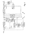
- A transmission system like that shown in
Figure 1 is generally used for transferring a digital video image in compressed form. The video image is formed of sequential frames. In some prior art video transmission systems, for example those according to the ITU-T H.261/H.263 recommendations, at least three frame types are defined: an I-frame (Intra), a P-frame (Predicted or Inter), and a B-frame (Bi-directional). The I-frame is generated solely on the basis of information contained in the image itself, wherein at the receiving end, this I-frame can be used to form the entire image. P-frames are formed on the basis of a preceding I-frame or P-frame, wherein at the receiving stage a preceding I-frame or P-frame is correspondingly used together with the received P-frame in order to reconstruct the image. In the composition of P-frames, for instance, motion compensation is used to compress the quantity of information. B-frames are formed on the basis of one or more preceding P-frames or I-frames and/or one or more following P-or I-frames. - The frames are further divided into blocks. One or more such blocks forms a block region. There can generally be four different region types: Intra region, copy region, coded region, and not-coded region. An intra region is a block region in which the blocks are coded independently without reference to any other frame. A copy region consists of blocks which are obtained by copying the content of the reference frame into exactly the same location without any motion compensated prediction. A coded region consists of blocks which are obtained using motion compensated prediction and prediction error coding. The prediction error is a difference between the pixel values of the actual frame and a reconstructed frame which is formed in the coding / decoding system using motion compensated prediction, as will be described in further detail later in the text. The prediction error is coded and sent to a receiver. A not-coded region is obtained using motion compensated prediction only. In fact the not-coded region is equivalent to a copy region if the motion information equals 0. All the block regions of one frame are not necessarily similar types, but one frame can comprise block regions which are of different types.
- Referring to
Figure 1 , which illustrates a typical encoding and decoding system (codec) used, for example, in the transmission of digital video, a current video frame to be coded comes to thetransmission system 10 as input data In(X,y). The input data In(x,y) typically takes the form of pixel value information. In thedifferential summer 11 it is transformed into a prediction error frame En(x,y) by subtracting from it a prediction frame Pn(x,y) formed on the basis of a previous image. The prediction error frame is coded inblock 12 in a manner described hereinafter, and the coded prediction error frame is directed to amultiplexer 13. To form a new prediction frame, the coded prediction error frame is also directed to adecoder 14, which produces a decoded prediction error frame Ên(x,y) which is summed in asummer 15 with the prediction frame Pn(x,y), resulting in a decoded frame În(x,y). The decoded frame is saved in aframe memory 16. To code the next frame, the frame saved in theframe memory 16 is read as a reference frame Rn(x,y) and is transformed into a new prediction frame Pn(x,y) in a motion compensation andprediction block 17, according to the formula:
- The pair of numbers [Dx(x,y), Dy(x,y)] is called the motion vector of the pixel at location (x,y) and the numbers Dx(x,y) and Dy(x,y) are the horizontal and vertical shifts of the pixel. They are calculated in a
motion estimation block 18. The set of motion vectors [Dx(·), Dy(·)] consisting of all motion vectors related to the pixels of the frame to be compressed is also coded using a motion model comprising basis functions and coefficients. The basis functions are known to both the encoder and the decoder. The coefficient values are coded and directed to themultiplexer 13, which multiplexes them into the same data stream with the coded prediction error frame for sending to a receiver. In this way the amount of information to be transmitted is dramatically reduced. - Some frames can be partly, or entirely, so difficult to predict that it is not practical to use motion compensated prediction when coding them. These frames or parts of frames are coded using intra-coding without prediction, and therefore it is not necessary to send motion vector information relating to them to the receiver.
- In the
receiver system 20, ademultiplexer 21 separates the coded prediction error frames and the motion information transmitted by the motion vectors and directs the coded prediction error frames to adecoder 22. Thedecoder 22 produces a decoded prediction error frame Ên(x,y), which is summed in asummer 23 with the prediction frame Pn(x,y) formed on the basis of a previous frame, resulting in a decoded frame În(x,y). The decoded frame is directed to anoutput 24 of the decoder and at the same time saved in aframe memory 25. When decoding the next frame, the frame saved in the frame memory is read as a reference frame and transformed into a new prediction frame in the motion compensation andprediction block 26, according to formula (1) presented above. - The coding method applied in
block 12 to the coding of the prediction error frame or to the intra-coding of a frame or part of a P-frame to be sent without prediction, is generally based on a transformation, the most common of which is the Discrete Cosine Transformation, DCT. The frame is divided into adjacent blocks having a size of e.g. 8 x 8 pixels. In coding and decoding, the blocks are processed independent of one another. The transformation is calculated for the block to be coded, resulting in a series of terms. The coefficients of these terms are quantized on a discrete scale in order that they can be processed digitally. Quantization causes rounding errors, which can become visible in an image reconstructed from blocks, so that there is a discontinuity of pixel values at the boundary between two adjacent blocks. Because a certain decoded frame is used for calculating the prediction frame for subsequent predicted frames, these errors can be propagated in sequential frames, thus causing visible edges in the image reproduced by the receiver. Image errors of this type are called blocking artefacts. - Some prior art methods are known for removing blocking artefacts. These methods are characterized by the following features:
- determining which pixel / pixels require value correction in order to remove the blocking artefact,
- determining a suitable low-pass filtering for each pixel to be corrected, based on the values of other pixels contained by a filtering window placed around the pixel,
- calculating a new value for the pixel to be corrected, and
- rounding the new value to the closest digitized pixel value.
- Factors that influence the selection of a filter and the decision whether to use filtering can be, for example, the difference between the values of pixels across the block boundary, the size of the quantization step of the coefficients received as the transformation result, and the difference of the pixel values on different sides of the pixel being processed.
- The publication
GB 2 329 090 - It has been found that prior art method tend to remove lines that belong to real features of the image. On the other hand, prior art methods are not always capable of removing all blocking artefacts.
- An objective of the present invention is to present a new kind of filtering arrangement for reducing blocking artefacts. The invention also has the objective that the method and associated device operate more reliably and efficiently than prior art solutions.
- The method according to the invention adjusts filtering parameters according to the type of blocks whose boundary is to be filtered. Different filtering parameters are chosen according to the type of block on either side of the boundary in order to yield an improved filtering result.
- The objectives of the invention are achieved by adapting the selection of pixels for filtering and the filtering process more flexibly than before to the features of the frame and the environment of the filtering point and by taking into account the nature/type of the blocks to be filtered.
- According to a first aspect of the invention, there is provided a method for reducing visual artefacts in a frame that is coded by blocks, characterized by what is disclosed in
claim 1. - According to a second aspect of the invention, there is provided a device for implementing the method according to the invention. The device according to the invention is characterized by what is disclosed in
claim 16. - According to a third aspect of the invention, there is provided an encoder as defined by
claim 31. - According to a fourth aspect of the invention, there is provided a decoder as defined by
claim 32. - According to a fifth aspect of the invention, there is provided a codec as defined by
claim 33. - According to a sixth aspect of the invention, there is provided a mobile terminal as defined by
claim 34. - According to a seventh aspect of the invention, there is provided a storage medium characterized by what is disclosed in
claim 35. - Because blocking artefacts only occur at block boundaries, according to the invention, filtering is advantageously only applied to pixels at block boundaries and the vicinity thereof. Edges that are part of the image can reside anywhere in the image area. In order that only pixels containing blocking artefacts are selected for corrective filtering and that the quality of edges that are part of the image itself is not affected during filtering, the following assumptions are made:
- Changes in pixel values associated with edges that are part of the image are generally larger than those associated with blocking artefacts, and those edges within the image, where the pixel value change is small, do not suffer considerably from the rounding of the pixel value difference caused by filtering.
- Because the image to be coded is generally divided into blocks both vertically and horizontally, the image contains both vertical and horizontal block boundaries. With regard to vertical block boundaries, there are pixels to the right and left of the boundary, and with regard to horizontal block boundaries, there are pixels above and below the boundary. In general, the location of the pixels can be described as being on a first or a second side of the block boundary. In an exemplary embodiment of the filtering method according to the invention, the number of pixels to be corrected, the characteristic features of the filter being used and the size of the filtering window depend on the following factors:
- a) The type of block on either side of the boundary (e.g. inter, copy, coded, not-coded),
- b) the difference in pixel values Δ across the block boundary. The difference can be defined in many ways. One definition is Δ = |r1 - I1|, where r1 is the value of the pixel on the first side of the block boundary closest to the boundary, and I1 is the value of the pixel on the second side of the block boundary closest to the boundary,
- c) the size of the quantization step QP of the coefficients received as the result of the transformation used in coding, and
- d) differences in pixel values between the pixels on the first side of the block boundary, and correspondingly between the pixels on the second side of the block boundary.
- In an advantageous embodiment of the method according to the invention, the number of the pixels selected for filtering can vary, and it is not necessarily the same on different sides of a block boundary. The number of pixels also depends on the type of block on either side of the boundary. Because the number of pixels is adapted to the general features of the image information contained by the frame in a particular region according to the factors mentioned above, the method produces a better filtering result than that provided by prior art methods. A "better" result in this context is one in which blocking artefacts are reduced to a greater extent while real edges in the image are affected to a lesser degree. This means that a larger amount of blocking artefacts can be removed without weakening the real image edges unreasonably.
- It should be noted that in other embodiments of the invention, the factors affecting the filtering performed at a block boundary may differ from those presented above.
- In the following, the invention will be described in more detail with reference to the preferred embodiments and the accompanying drawings, in which
- Figure 1
- represents a a digital video encoding and decoding system (codec) according to prior art,
- Figure 2
- represents the location of pixels in relation to a block boundary in an exemplary embodiment of the method according to the invention,
- Figure 3
- represents alternatives for locating the filtering method according to the invention in a digital video encoding and decoding system,
- Figure 4
- is a schematic representation of a device for implementing a method according to the invention,
- Figure 5
- represents a device according to
Figure 4 in operation, and - Figure 6
- is a schematic representation of a portable video telecommunications device implementing a method according to the invention.
- In the above, in connection with the description of the prior art, reference was made to
Figure 1 .In the following description of the invention and its preferred embodiments, reference will be made mostly toFigures 2 to 5 . The same reference numbers are used for corresponding parts in the figures. -
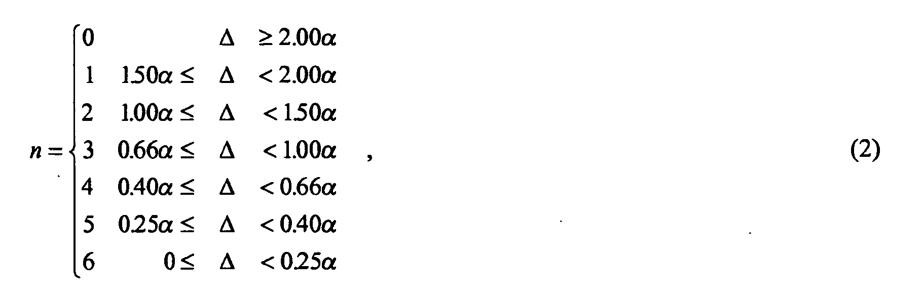
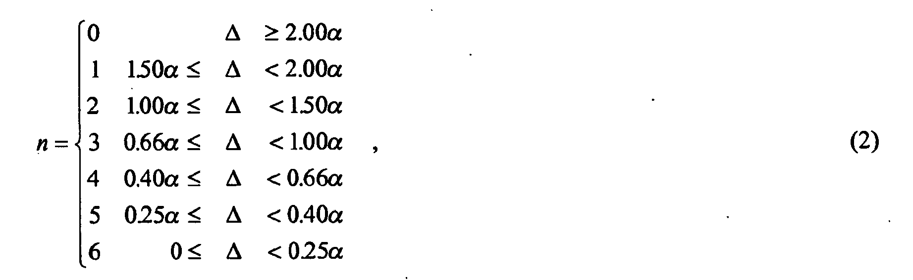
Figure 2 shows the location of the pixels r1 - r6 and I1 - I6 in relation to avertical block boundary 30. To implement the method according to the invention, certain parameters are specified. Parameter n is the largest number of pixels to be examined from the block boundary in one direction, and in the case ofFigure 2 its value is 6. It is advantageous to select the value of the parameter n so that it has a certain relation to both the difference of the pixel values Δ across the block boundary and to the size of the quantization step QP of the coefficients received as the result of image coding. Furthermore, the value of parameter n is advantageously smaller than or equal to the number of pixels in the block in the direction of examination, to avoid possible blocking artefacts associated with previous block boundaries spreading to the block boundary under examination. The following definition is recommended for use in a preferred embodiment of the invention applied to image blocks comprising 8x8 pixels:
wherein α = QP·log(QP). If QP has a different value in blocks on different sides of the block boundary, the smaller value of QP is used in the calculations, as well as in all cases presented hereinafter, in which a definition includes reference to one QP value only. The invention does not place any limitations on the determination of the value of parameter n, but according to the guidelines of equation (2), it is advantageous that its value is generally higher when the difference of pixel values Δ across the block boundary is small in comparison with the size of the quantization step QP of the coefficients received as the result of the coding transformation. If the difference between the pixel values Δ is large, there is a high probability that there is a real image edge at the block boundary, and in this case the pixels are preferably not examined for filtering at all (n=0). - In the next step of the filtering method according to the invention, region type information concerning the two neighbouring blocks is examined, i.e. the type of the blocks on both sides of the block boundary in question is considered. According to the region type information, the value of the parameter n may further be limited (truncated) to provide even better results for reducing blocking artefacts. The region type information is included e.g. in the coded information relating to the pixels of a particular block, wherein that information is maintained, or temporarily stored, during decoding of the block until a truncated value ntr for parameter n is determined.
- Table 1 shows truncation values according to an advantageous embodiment of the present invention. Table 1 applies in a situation where the maximum value of n is 6, and, of course, different truncated values would be appropriate in situations where the maximum value is other than 6. The truncation values are used for the first and second sides of the block boundary depending on the region type of the block on the first side of the block boundary and on the region type of the block on the second side of the block boundary.
TABLE 1 type of the Block on the Second side of a boundary type of the Block on the First side of a boundary INTRA COPY CODED NOT_CODED INTRA n n 2 2 n 4 n 2 COPY 2 2 2 2 2 4 2 2 CODED 4 n 4 2 4 4 4 2 NOT_CODED 4 n 2 2 2 4 2 2 - Each cell of Table 1, corresponding to a particular region type combination, is split into two parts. The value on the left gives the truncation value trval for the first side of the block boundary and the value on the right gives the truncation value trval for the second side of the boundary. If the value of parameter n exceeds the value given in Table 1, n is truncated to the truncation value trval in Table 1. If, however, the value of the overall activity parameter n does not exceed the value given in Table 1, the value of the parameter n (originally determined from equation (2)) is retained. In Table 1 the symbol "n" indicates that further truncation is not performed and the parameter value is retained. The truncated value ntr for the parameter n can also be represented by the formula:

- The same table can be used both for filtering across vertical block boundaries (horizontal filtering) by putting "Left"/"Right" in place of "First"/"Second" and for filtering across horizontal block boundaries (vertical filtering) by putting "Bottom"/"Up" in place of "First"/"Second", respectively. Now, the value on the left gives the truncation value for the pixels on the left/below the block boundary and the value on the right gives the truncation value for the pixels on the right/above the boundary.
- To further clarify the use of Table 1, an example situation is presented in the following. In this illustrative example situation "horizontal filtering" is performed across a
vertical block boundary 30. Assuming that the value for parameter n, calculated from equation 2, is e.g. 4, the block on the left-hand side of theblock boundary 30 in question is of the Intra type, and the block on the right-hand side of theblock boundary 30 in question is of the Not-coded type, Table 1 indicates that the truncation value for the left-hand side is n and the truncation value for the right-hand side is 2. This means that the 4 pixels closest to the block boundary (=the calculated value of n) are selected for examination from the left-hand side of the boundary, and 2 pixels closest to the block boundary (=the truncated value of n) are selected for examination from the right-hand side. - Another example situation is presented in the following. In this illustrative example situation "horizontal filtering" is performed across a
vertical block boundary 30. Assuming that the value of parameter n calculated from equation (2) is e.g. 4, and the blocks on both sides of theblock boundary 30 in question are of the Copy type, Table 1 indicates that the truncation value for the left-hand side is 2 and the truncation value for the right-hand side is 2. This means that the 2 pixels closest to the block boundary (=the truncated value of n) are selected for examination from the left-hand side of the boundary, and the 2 pixels closest to the block boundary (=the truncated value of n) are selected for examination from the right-hand side. - For bi-directionally predicted frames (B-frames), truncation of the parameter n is advantageously not applied because there is no unique block type information.
- The next step in the filtering method according to the invention is to determine the values of the parameters dl and dr, which represent activity, or the differences of pixel values between pixels on one side of the block boundary. A preferred definition for dr is the following:
- dr = 6, if |r1 - rj| ≤ β/j with all j∈[1,6],
- otherwise: dr = i, where i fulfils the conditions

- Here, the auxiliary parameter β = 4·log(QP). The value of parameter dl is determined similarly, except that all r's are replaced by I's and the corresponding truncated value ntr for the parameter n must be used. The number 6 appears in definition (4) because, according to equation (2), the highest possible value of n is 6 in this case. If n is defined differently, but the parameters dr and dl are defined according to definition (4), the number 6 must be replaced by the highest possible value of n according to the new definition.
- It is advantageous that the values of the parameters dr and dl are calculated independent of one another, because the image information contained by the frame can be different on different sides of the block boundary. The invention does not limit the definition of parameters dr and dl, but according to the guidelines of definition (4), it is advantageous that these parameters are used to limit the blocking artefact processing relatively close to the block boundary, if there is a real image edge near the block boundary. The essential features of definition (4) can be summarised as follows: the value of parameter dr (and correspondingly the value of parameter dl) provides an indication of how many pixels counted from the block boundary have approximately the same value as the pixel at the block boundary.
- A high value of parameter rr (e.g. 6) indicates that the difference between the pixel values at the block boundary is relatively small compared with the general variation of the pixel values within the block. In this case, it is possible that there is a real image edge near the block boundary. By selecting a sufficiently small value of parameter dr (or dl), it is possible to restrict the filtering aimed at correcting blocking artefacts so that it does not have a deteriorating effect on a real image edge close to the block boundary. In some situations, a large number of pixels counted from the block boundary have approximately the same value as the pixel at the block boundary. In that case, definition (4) would give the parameter dr (or dl) a relatively high value. However, if there is a clear discontinuity in pixel values between the blocks, the parameter n has a small value and the truncated value ntr is used in the definition (4) which make sure that an unreasonably high value is not selected as the value of the parameter dr (or dl). Otherwise, a relatively high value of the parameter dr (or dl) would result in unnecessary filtering.
- If blocks on both sides of the block boundary are Intra-type blocks, the truncation has no effect on the selection of the parameter values n, dr and dl. On the other hand, if at least one of the blocks has a type other than Intra, the truncation of the value n according to the formula (3) may limit the number of pixels filtered. This has the advantage that the block boundaries are not smoothed too much.
- In addition, the largest possible number of pixels to be filtered must be decided. This does not have a notation of its own in
Figure 2 , but it can be e.g. 3, which means that filtering can only be used to correct the value of the pixels r1, r2, r3, I1, I2 and I3. - When the values of the parameters n, ntr, dr and dl have been determined, filtering is carried out using a suitable filter. The invention does not limit the kind of filter that can be used, but a filtering arrangement that has been found preferable, will be described in the following. Filtering is used to determine a new value for the pixels selected for filtering. In a preferred embodiment of the invention, a new pixel value is determined for a given pixel by calculating the mean of the pixel values that appear in a filtering window. In the preferred embodiment, the filtering window is symmetrical with regard to the pixel to be filtered and contains, in addition to the pixel to be filtered, one, two or three pixels from both sides, depending on the values of the parameters dr and dl as described hereinafter. Of course, these are only examples and other values could be chosen in situations where n, ntr, dr and dl are defined differently. The calculated mean value is rounded to the closest digitized pixel value, whereby it becomes the new value of the filtered pixel.
- Table 2 shows the determination of the width of the filtering window for the pixels r1, r2 and r3 according to the value of parameter dr in a preferred embodiment of the invention. The values of the pixels I1, I2 and I3 are determined in the same manner according to the value of the parameter dl. In the table, "X" means that the pixel in question is not filtered at all, and the number means that the filtering window includes a number of pixels shown by the number from each side of the pixel being examined. Among other things, Table 2 shows that for filtering to be applied to any pixel, parameters dr and dl must both have a value greater than 1.
dr(dl > 1) r1 r2 r3 1 X X X 2 1 X X 3 1 1* X 4 2 2 X 5 2 2 2** 6 3 or 2*** 3 3 * the filtered value of pixel r1 is used for filtering of pixel r2
** the filtered values of pixels r1 and r2 are used for filtering pixel r3
*** 3 if dl > 2, otherwise 2. - The above description relates to implementing the filtering on one horizontal part of a pixel row, which is 12 pixels long and located symmetrically on both sides of a vertical block boundary. The description can be easily generalized to concern vertical parts of pixel columns, which are located symmetrically on both sides of a horizontal block boundary:
Figure 2 can be turned 90 degrees counter-clockwise, wherebyblock boundary 30 becomes horizontal, and the pixels shown in the figure form part of the vertical pixel column so that pixels r1 - r6 are the pixels above and pixels I1 - I6 are the pixels below the boundary. To filter block boundaries throughout the whole frame, applying the method according to the invention, all vertical block boundaries of the frame are examined row by row and all horizontal block boundaries are examined column by column. The order has no significance as such, and thus all the horizontal block boundaries of the frame could be examined first column by column, and then all the vertical block boundaries row by row. In an advantageous embodiment of the invention, filtering is repeated line by line, i.e. the first line of the pixels in the blocks (besides the boundary) is filtered first, then the second line, etc. -
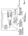
Figure 3 shows at which points a digital image encoding and decoding system (codec) according to prior art can be improved by applying filtering according to the invention. The first alternative is to place a block implementing the filtering method according to the invention in the output of the decoder of the receiver, as illustrated byreference number 31. In this case, block boundaries in the video frame are filtered after all blocks within the frame have been decoded. This requires block type information to be stored for all the blocks in one frame. Another alternative is to place the filtering block in the receiver before the point at which the decoded frame is directed to theframe memory 25 for forming a prediction frame, as illustrated byreference number 32. In this case, block type information for all blocks within the frame must also be stored, as block boundary filtering is still performed after decoding and reconstructing the entire frame. However, this alternative has the advantage that the removal of blocking artefacts also has an effect on the formation of a prediction frame, whereby blocking artefacts in one frame are not propagated via the prediction frame to subsequent frames. In order to achieve the effect just described, the block that performs filtering according to the invention can be placed either before or after the frame memory 25.However, the location shown byreference number 32 is preferred, because when applied at this stage, the filtering influences simultaneously the frame to be output by the receiving decoder and the frame to be saved in the memory. In the transmitter, a block implementing the filtering method according to the invention can be placed as shown byreference numbers frame memory 16. In this way, the invention can also be used to produce a corrected prediction frame at the transmission end. - In a particularly advantageous embodiment of the invention, the block carrying out the filtering according to the invention is implemented in a digital signal processor or a corresponding device suited for processing a digital signal, which can be programmed to apply predetermined processing functions to a signal received as inputs data.
Figure 4 presents the functional elements of a block carrying out the filtering method according to the invention, implemented as a digital signal processor. Correspondingly, operation of the filtering block is illustrated byFigure 5 . Referring first toFigure 4 , the functional elements are programmed with functional definitions (35 - 39) for calculating the parameters that control the filtering method according to the invention. Advantageously, the functional definitions are loaded into the signal processor in connection with its manufacture or programming . During operation according toFigure 5 , the frame is saved temporarily inregister 41, so that it can be processed by the signal processor. - Processing of the frame proceeds block-by-block. At a given instant, a number of pixels indicated by the parameter n, ntr, according to the definitions provided in Table 1, are selected to be examined 42 from each side of a certain point on a certain block boundary, the d-
parameters 43 are calculated, and filtering 44 is performed. These operations are repeated until all boundaries of all blocks have been filtered/processed, after which the frame can be output fromregister 41 and a new frame saved for processing. The measures according toFigures 4 and5 can be carried out in a separate signal processor or they can be implemented in a general processor which also contains other arrangements for signal processing. - A storage medium can be used for storing a software program comprising machine executable steps for performing the method according to the invention. In an advantageous embodiment of the invention, the software program is read from the storage medium to a device comprising programmable means, e.g. a processor, for performing the method of the invention.
- The invention can be modified without departing from the scope defined by the claims presented hereinafter, using the capabilities of a person skilled in the art without actual inventive steps. For example, the parameter Δ can be calculated using the formula Δ = |(r1 + r2) - (l1 + l2)| or some other formula considered suitable. The definitions of the other parameters presented above should also be considered as examples only. A particularly advantageous use of the invention is in mobile video telecommunication applications, digital television receivers and other devices that at least receive and decode digital video image. It should further be noted that in general the method according to the invention may be applied to any image coding method in which an image is encoded / decoded on a block-by-block basis, including individual (i.e. still) digital images.
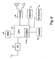
-
Figure 6 shows a mobile terminal 46 intended for use as a portable video telecommunications device and applying the method according to the invention. Advantageously, the mobile terminal 46 comprises at least display means 47 for displaying images, audio means 48 for capturing and reproducing audio information, akeyboard 49 for inputting e.g. user commands, aradio part 50 for communicating with a mobile communications network (not shown), processing means 51 for controlling the operation of the device, memory means 52 for storing information, and preferably acamera 53 for taking images. - The present invention is not solely restricted to the above presented embodiments, but it can be modified within the scope of the appended claims.
Claims (35)
- A method for reducing visual artefacts in a frame of a digital video signal, which is coded by blocks and then decoded, a block type being defined according to the prediction encoding method for a block selected from a predetermined set of coding types, the method comprising performing an adaptive block boundary filtering operation on a block boundary formed between a first decoded image block on a first side of the block boundary and a second decoded image block on a second side of the block boundary, characterized in that the first decoded image block have been encoded using a first type of prediction encoding method and the second decoded image block have been encoded using a second type of prediction encoding method, wherein at least one parameter of the filtering operation is determined based on the types of the first and second prediction encoding methods, and the first and second type of prediction encoding methods are selected from a group of prediction encoding methods comprising at least: intra coding, copy coding, motion-compensated prediction coding, and not-coded coding.
- A method according to Claim 1, characterised in that the frame comprises at least one region of blocks, each block within said region having a region type, and that the filtering performed on the block boundary depends on a region type of the blocks in the environment of the block boundary (30).
- A method according to Claim 1 or 2, characterised in that said at least one parameter is selected from a group comprising: a number of pixels to be examined, a number of pixels to be filtered, an activity measure providing an indication of the difference between pixel values on one side of the block boundary, a filtering window.
- A method according to any of Claims 1 to 3, in which a number of pixels (n) is selected for examination from at least one side of the block boundary (30), characterized in that the number of pixels (n) selected for examination depends on the image content of the frame in the environment of the block boundary (30), and that the number of pixels (n) selected for examination further depends on the block type of a block in the environment of the block boundary (30).
- A method according to Claim 4, characterised in that the number of pixels (n) selected for examination depends on the difference in pixel value (Δ) between pixels across the block boundary.
- A method according to Claim 4 or 5, characterized in that the number of pixels selected for examination depends on the size of the quantization step (QP) of the coefficients used in the coding of the blocks.
- A method according to Claim 6, characterized in that the number of pixels (n) selected for examination is determined by the formula:
wherein Δ is the difference in value between pixels across the block boundary, α = QP·log(QP) and QP is the size of the quantization step of the coefficients used in the coding of the blocks. - A method according to Claim 5, 6, or 7, characterized in that the number of pixels (n) is first defined according to the image content of the frame in the environment of the block boundary (30), and the number of pixels (n) is further truncated according to the block type of a block in the environment of the block boundary (30) to give a truncated number of pixels (ntr) for examination.
- A method according to Claim 8, characterized in that the truncated number of pixels (ntr) is determined by selecting a truncation value (trval) according to the table
Region type of the Block on the Second side Region type of the Block on the First side INTRA COPY CODED NOT_CODED INTRA n n 2 2 n 4 n 2 COPY 2 2 2 2 2 4 2 2 CODED 4 n 4 2 4 4 4 2 NOT_CODED 2 n 2 2 2 4 2 2 
- A method according to any preceding Claim, characterized in that certain pixels to be filtered are selected, and a new value is determined for each pixel to be filtered on the basis of pixels that appear in a filtering window set around the pixel.
- A method according to any preceding Claim, characterized in that pixels to be filtered are selected from the pixels selected for examination.
- A method according to Claim 10 or 11, characterized in that the new value of the pixel to be filtered is the mean value of the pixels that appear in the filtering window.
- A method according to Claim 10, characterized in that for determining a new value for the pixels to be filtered on the first side of the block boundary, said filtering window is used, and the size of the window is determined according to the table
dr (dl > 1) r1 r2 r3 1 X X X 2 1 X X 3 1 1* X 4 2 2 X 5 2 2 2** 6 3 or 2*** 3 3 where
* the filtered value of pixel r1 is used for filtering of pixel r2
** the filtered values of pixels r1 and r2 are used for filtering pixel r3
*** 3 if dl > 2, otherwise 2, - A method according to Claim 13, characterized in that said activity is determined on the basis of changes in pixel values.
- A method according to Claim 13 or 14, characterized in that
dr = 6, if |r1 - rj| ≤ β/j with all j∈[1,6],
otherwise: dr = i, where i meets the conditions


- A device for reducing visual artefacts in a frame of a digital video signal, which is coded by blocks and then decoded, a block type being defined according to the prediction encoding method for a block selected according to a predetermined set of coding types, the device comprising means (39) for performing an adaptive block boundary filtering operation on a block boundary formed between a first decoded image block on a first side of the block boundary and a second decoded image block on a second side of the block boundary, characterized in that the first decoded image block have been encoded using a first type of prediction encoding method and the second decoded image block have been encoded using a second type of prediction encoding method, wherein the device comprises means for determining at least one parameter of the filtering operation based on the types of the first and second prediction encoding methods, the first type of prediction encoding method is intra coding, copy coding, motion-compensated prediction coding, or not-coded coding, and the second type of prediction encoding method is intra coding, copy coding, motion-compensated prediction coding, or not-coded coding.
- A device according to Claim 16, characterised in that the filter is arranged such that the frame comprises at least one region of blocks, each block within said region having a region type, and that the filtering performed on the block boundary depends on a region type of the blocks in the environment of the block boundary (30).
- A device according to Claim 17, characterised in that said at least one parameter is selected from a group comprising: a number of pixels to be examined, a number of pixels to be filtered, an activity measure providing an indication of the difference between pixel values on one side of the block boundary, a filtering window.
- A device according to Claim 17, or 18, characterized in that it comprises means (42) that operate adaptively according to the image content of the frame, for selecting a number of pixels (n) for examination, and that means (42) for selecting a number of pixels (n) for examination comprises further means (42) for examining the block type of a block in the environment of the block boundary (30).
- A device according to Claim 19, characterised in that it comprises means (42) for selecting the number of pixels (n) for examination depending on the difference in pixel value (Δ) between pixels across the block boundary.
- A device according to any of Claims 16 to 20, characterized in that it comprises means (42) for selecting a number of pixels (n) for examination depending on the size of the quantization step (QP) of the coefficients used in the coding of the blocks.
- A device according to Claim 21, characterized in that the means (42) for selecting the number of pixels (n) for examination comprises means (35) for determining said number of pixels according to the formula:
wherein Δis the difference in value between pixels across the block boundary, α = QP·log(QP) and QP is the size of the quantization step of the coefficients used in the coding of the blocks. - A device according to any of Claims 16 to 22, characterized in that it comprises means (42) for truncating the number of pixels (n) selected for examination on the basis of the block type of a block in the environment of the block boundary.
- A device according to any of Claims 16 to 23, characterized in that the means (42) for selecting a number of pixels for examination comprises means for defining the number of pixels (n) according to the image content of the frame in the environment of the block boundary (30), and means for truncating the number of pixels (n) according to the block type of a block in the environment of the block boundary (30).
- A device according to Claim 24, characterized in that the means for truncating the number of pixels (n) comprises means for selecting a truncation value (trval) according to the table:
Type of the Block on the Second side Type of the Block on the First side INTRA COPY CODED NOT_CODED INTRA n n 2 2 n 4 n 2 COPY 2 2 2 2 2 4 2 2 CODED 4 n 4 2 4 4 4 2 NOT CODED 2 n 2 2 2 4 2 2 
- A device according to any of Claims 16 to 25, characterized in that it comprises means (42) for selecting certain pixels to be filtered, means (42) for defining a filtering window, and means for determining a new value for each pixel to be filtered on the basis of pixels that appear in a filtering window set around the pixel.
- A device according to Claim 26, characterized in that the means for determining a new value for each pixel comprises means for calculating a mean value of the pixels that appear in the filtering window.
- A device according to Claim 22, characterized in that the means for determining a new value for each pixel comprises means for using said filtering window for the pixels to be filtered on the first side of the block boundary, and means for determining the size of the window according to the table
dr(dl > 1) r1 r2 r3 1 X X X 2 1 X X 3 1 1* X 4 2 2 X 5 2 2 2** 6 3 or 2*** 3 3 where
* the filtered value of pixel r1 is used for filtering of pixel r2
** the filtered values of pixels r1 and r2 are used for filtering pixel r3
*** 3 if dl > 2, otherwise 2, - A device according to Claim 28, characterized in that
dr = 6, if |r1 - rj| ≤ β/j with all j∈[1,6],
otherwise: dr = i, where i meet the conditions


wherein the auxiliary parameter β = 4·log(QP) and QP is the size of the quantization step of the transformation coefficients used in transformation coding of the blocks, and the value of the parameter dl being determined similarly, with the exception that all r's are replaced by I's. - A device according to any of Claims 16 to 29, characterized in that it comprises programmable means (42) for selecting pixels from a saved frame as the pixels to be examined, programmable means (45) for selecting pixels to be filtered from among the pixels to be examined, and programmable means (44) for determining the new value of the pixels to be filtered.
- A video encoder (10) comprising the device according to any of the claims 16 to 30.
- A video decoder (20) comprising the device according to any of the claims 16 to 30.
- A video codec (10, 20) comprising the device according to any of the claims 16 to 30.
- A mobile terminal (46) comprising the device according to any of the claims 16 to 30.
- A storage medium for storing a software program comprising machine executable steps for coding and decoding a digital video signal by blocks, a block type being defined according to the prediction encoding method for a block selected according to a predetermined set of coding types, for reducing visual artefacts due to a block boundary by filtering, the software program comprising machine executable steps for performing an adaptive block boundary filtering operation on a block boundary formed between a first decoded image block on a first side of the block boundary and a second decoded image block on a second side of the block boundary, characterized in that the first decoded image block have been encoded using a first type of prediction encoding method and the second decoded image block have been encoded using a second type of prediction encoding method, wherein the software program further comprises machine executable steps for determining at least one parameter of the filtering operation based on the types of the first and second prediction encoding methods, and the first and second type of prediction encoding methods are selected from a group of prediction encoding methods comprising at least: intra coding, copy coding, motion-compensated prediction coding, and not-coded coding.
Applications Claiming Priority (3)
| Application Number | Priority Date | Filing Date | Title |
|---|---|---|---|
| FI20000120 | 2000-01-20 | ||
| FI20000120A FI117533B (en) | 2000-01-20 | 2000-01-20 | Procedure for filtering digital video images |
| PCT/FI2001/000049 WO2001054415A1 (en) | 2000-01-20 | 2001-01-22 | A method and associated device for filtering digital video images |
Publications (2)
| Publication Number | Publication Date |
|---|---|
| EP1186177A1 EP1186177A1 (en) | 2002-03-13 |
| EP1186177B1 true EP1186177B1 (en) | 2011-08-24 |
Family
ID=8557147
Family Applications (1)
| Application Number | Title | Priority Date | Filing Date |
|---|---|---|---|
| EP01902442A Expired - Lifetime EP1186177B1 (en) | 2000-01-20 | 2001-01-22 | A method and associated device for filtering digital video images |
Country Status (12)
| Country | Link |
|---|---|
| US (2) | US9800891B2 (en) |
| EP (1) | EP1186177B1 (en) |
| CN (2) | CN1756362B (en) |
| AT (1) | ATE522088T1 (en) |
| AU (1) | AU778990B2 (en) |
| CA (1) | CA2374523C (en) |
| ES (1) | ES2368706T3 (en) |
| FI (1) | FI117533B (en) |
| HK (2) | HK1048411B (en) |
| RU (2) | RU2295203C2 (en) |
| SG (1) | SG128476A1 (en) |
| WO (1) | WO2001054415A1 (en) |
Families Citing this family (46)
| Publication number | Priority date | Publication date | Assignee | Title |
|---|---|---|---|---|
| US7929610B2 (en) * | 2001-03-26 | 2011-04-19 | Sharp Kabushiki Kaisha | Methods and systems for reducing blocking artifacts with reduced complexity for spatially-scalable video coding |
| US6931063B2 (en) | 2001-03-26 | 2005-08-16 | Sharp Laboratories Of America, Inc. | Method and apparatus for controlling loop filtering or post filtering in block based motion compensationed video coding |
| US7450641B2 (en) * | 2001-09-14 | 2008-11-11 | Sharp Laboratories Of America, Inc. | Adaptive filtering based upon boundary strength |
| KR100525785B1 (en) * | 2001-06-15 | 2005-11-03 | 엘지전자 주식회사 | Filtering method for pixel of image |
| WO2003021936A2 (en) * | 2001-09-05 | 2003-03-13 | Emblaze Semi Conductor Ltd | Method for reducing blocking artifacts |
| US20050013494A1 (en) * | 2003-07-18 | 2005-01-20 | Microsoft Corporation | In-loop deblocking filter |
| US7724827B2 (en) * | 2003-09-07 | 2010-05-25 | Microsoft Corporation | Multi-layer run level encoding and decoding |
| US8625680B2 (en) * | 2003-09-07 | 2014-01-07 | Microsoft Corporation | Bitstream-controlled post-processing filtering |
| US9715898B2 (en) * | 2003-12-16 | 2017-07-25 | Core Wireless Licensing S.A.R.L. | Method and device for compressed-domain video editing |
| EP1555832A3 (en) * | 2004-01-14 | 2011-05-18 | Samsung Electronics Co., Ltd. | Adaptive loop filtering for reducing blocking artifacts |
| GB2418093B (en) * | 2004-09-09 | 2007-03-28 | Imagination Tech Ltd | Method and apparatus for removing visible artefacts in video images |
| US20080084932A1 (en) * | 2006-10-06 | 2008-04-10 | Microsoft Corporation | Controlling loop filtering for interlaced video frames |
| US7876808B2 (en) * | 2006-11-30 | 2011-01-25 | Broadcom Corp. | Method and apparatus for adaptive noise and/or signal filtering in an HSDPA channel quality indicator (CQI) selection |
| PL2123051T3 (en) * | 2006-12-18 | 2011-04-29 | Koninl Philips Electronics Nv | Image compression and decompression |
| US8831086B2 (en) | 2008-04-10 | 2014-09-09 | Qualcomm Incorporated | Prediction techniques for interpolation in video coding |
| US9967590B2 (en) | 2008-04-10 | 2018-05-08 | Qualcomm Incorporated | Rate-distortion defined interpolation for video coding based on fixed filter or adaptive filter |
| JP4813517B2 (en) * | 2008-05-29 | 2011-11-09 | オリンパス株式会社 | Image processing apparatus, image processing program, image processing method, and electronic apparatus |
| US10123050B2 (en) | 2008-07-11 | 2018-11-06 | Qualcomm Incorporated | Filtering video data using a plurality of filters |
| WO2010052833A1 (en) * | 2008-11-07 | 2010-05-14 | 三菱電機株式会社 | Image encoding device and image decoding device |
| JP2012510202A (en) * | 2008-11-25 | 2012-04-26 | トムソン ライセンシング | Method and apparatus for sparsity-based artifact removal filtering for video encoding and decoding |
| JP5490404B2 (en) * | 2008-12-25 | 2014-05-14 | シャープ株式会社 | Image decoding device |
| US9143803B2 (en) | 2009-01-15 | 2015-09-22 | Qualcomm Incorporated | Filter prediction based on activity metrics in video coding |
| US8559733B2 (en) * | 2009-03-31 | 2013-10-15 | Citrix Systems, Inc. | Methods and systems for approximating progressive image encoding using image partitioning |
| US20120087595A1 (en) * | 2009-06-19 | 2012-04-12 | Mitsubishi Electric Corporation | Image encoding device, image decoding device, image encoding method, and image decoding method |
| JP5597968B2 (en) * | 2009-07-01 | 2014-10-01 | ソニー株式会社 | Image processing apparatus and method, program, and recording medium |
| JP2011049740A (en) * | 2009-08-26 | 2011-03-10 | Sony Corp | Image processing apparatus and method |
| US8787443B2 (en) | 2010-10-05 | 2014-07-22 | Microsoft Corporation | Content adaptive deblocking during video encoding and decoding |
| MA34906B1 (en) * | 2011-01-14 | 2014-02-01 | Ericsson Telefon Ab L M | UNBLOCKING FILTERING |
| US8964852B2 (en) | 2011-02-23 | 2015-02-24 | Qualcomm Incorporated | Multi-metric filtering |
| JP5291134B2 (en) | 2011-03-09 | 2013-09-18 | 日本電信電話株式会社 | Video encoding / decoding method, video encoding / decoding device and program thereof |
| JP5291133B2 (en) | 2011-03-09 | 2013-09-18 | 日本電信電話株式会社 | Image processing method, image processing apparatus, video encoding / decoding method, video encoding / decoding apparatus, and programs thereof |
| US9042458B2 (en) | 2011-04-01 | 2015-05-26 | Microsoft Technology Licensing, Llc | Multi-threaded implementations of deblock filtering |
| US8724701B1 (en) * | 2011-04-18 | 2014-05-13 | Google Inc. | Using object decomposition to improve the selection of example-based predictors |
| JP2014526818A (en) * | 2011-09-09 | 2014-10-06 | パナソニック インテレクチュアル プロパティ コーポレーション オブ アメリカ | Low-complexity deblocking filter decision |
| GB201119206D0 (en) | 2011-11-07 | 2011-12-21 | Canon Kk | Method and device for providing compensation offsets for a set of reconstructed samples of an image |
| RU2638743C1 (en) * | 2012-04-13 | 2017-12-15 | Мицубиси Электрик Корпорейшн | Image encoding device, image decoding device, image encoding method, and image decoding method |
| WO2013175736A1 (en) | 2012-05-25 | 2013-11-28 | パナソニック株式会社 | Video encoding method, video encoding device, video decoding method, video decoding device, and video encoding/decoding device |
| RU2679984C2 (en) | 2012-05-25 | 2019-02-14 | Вилос Медиа Интернэшнл Лимитед | Image encoding method, image encoding device, image decoding method, image decoding device and device for encoding and decoding images |
| MX2013015089A (en) | 2012-05-25 | 2014-02-21 | Panasonic Corp | Video image coding method, video image decoding method, video image coding device, video image decoding device, and video image coding-decoding device. |
| KR102060617B1 (en) * | 2012-06-04 | 2019-12-30 | 선 페이턴트 트러스트 | Video image encoding method, video image encoding device, video image decoding method, and video image decoding device |
| RU2696309C1 (en) | 2015-09-25 | 2019-08-01 | Хуавэй Текнолоджиз Ко., Лтд. | Video motion compensation device and method |
| EP3354028B1 (en) | 2015-09-25 | 2021-09-15 | Huawei Technologies Co., Ltd. | Apparatus and method for video motion compensation with selectable interpolation filter |
| KR102143736B1 (en) | 2015-09-25 | 2020-08-12 | 후아웨이 테크놀러지 컴퍼니 리미티드 | Video motion compensation apparatus and method |
| MY190412A (en) * | 2015-09-25 | 2022-04-21 | Huawei Tech Co Ltd | Adaptive sharpening filter for predictive coding |
| JP6556942B2 (en) | 2015-09-25 | 2019-08-07 | ホアウェイ・テクノロジーズ・カンパニー・リミテッド | Apparatus and method for video motion compensation |
| RU2640298C1 (en) * | 2015-10-12 | 2017-12-27 | Общество С Ограниченной Ответственностью "Яндекс" | Method for processing and storing images |
Family Cites Families (17)
| Publication number | Priority date | Publication date | Assignee | Title |
|---|---|---|---|---|
| US5225904A (en) * | 1987-10-05 | 1993-07-06 | Intel Corporation | Adaptive digital video compression system |
| US5218649A (en) * | 1990-05-04 | 1993-06-08 | U S West Advanced Technologies, Inc. | Image enhancement system |
| RU2042282C1 (en) | 1992-07-27 | 1995-08-20 | Санкт-Петербургский государственный электротехнический университет им.Ульянова (Ленина В.И.) | Device of digital encoding and decoding of television signal |
| US5768438A (en) | 1994-10-19 | 1998-06-16 | Matsushita Electric Industrial Co., Ltd. | Image encoding/decoding device |
| GB9502274D0 (en) * | 1995-02-06 | 1995-03-29 | Central Research Lab Ltd | Method and apparatus for coding information |
| DE69619002T2 (en) * | 1995-03-10 | 2002-11-21 | Toshiba Kawasaki Kk | Image coding - / - decoding device |
| DE19604050B4 (en) | 1995-08-17 | 2005-09-29 | Siemens Ag | Edge pixel smoothing of block-coded images - has edge pixels processed by edge filter having low=pass stages appropriate to motion vector ranges |
| US5896176A (en) * | 1995-10-27 | 1999-04-20 | Texas Instruments Incorporated | Content-based video compression |
| US5812702A (en) * | 1995-11-22 | 1998-09-22 | U S West, Inc. | System and method for enhancement of coded images using adaptive spatial filtering |
| EP0881837B1 (en) | 1997-05-30 | 2003-03-26 | STMicroelectronics S.r.l. | Post-processing method for reducing artifacts in block-coded digital images, and post-processing device for actuating such method |
| JP3967405B2 (en) * | 1996-10-09 | 2007-08-29 | テキサス インスツルメンツ インコーポレイテツド | Image signal encoding method |
| JP3800704B2 (en) | 1997-02-13 | 2006-07-26 | ソニー株式会社 | Video signal processing apparatus and method |
| FI106071B (en) | 1997-03-13 | 2000-11-15 | Nokia Mobile Phones Ltd | Adaptive filter |
| FI103003B1 (en) | 1997-06-13 | 1999-03-31 | Nokia Mobile Phones Ltd | Filtering procedure, filter and mobile terminal |
| KR100244290B1 (en) | 1997-09-09 | 2000-02-01 | 구자홍 | Method for deblocking filtering for low bit rate video |
| US6285801B1 (en) | 1998-05-29 | 2001-09-04 | Stmicroelectronics, Inc. | Non-linear adaptive image filter for filtering noise such as blocking artifacts |
| KR100720841B1 (en) | 1999-02-16 | 2007-05-25 | 코닌클리케 필립스 일렉트로닉스 엔.브이. | Video decoding device and method using a filtering step for block effect reduction |
-
2000
- 2000-01-20 FI FI20000120A patent/FI117533B/en not_active IP Right Cessation
-
2001
- 2001-01-19 US US09/766,035 patent/US9800891B2/en not_active Expired - Fee Related
- 2001-01-22 AU AU30275/01A patent/AU778990B2/en not_active Expired
- 2001-01-22 WO PCT/FI2001/000049 patent/WO2001054415A1/en active Application Filing
- 2001-01-22 CN CN2005101137676A patent/CN1756362B/en not_active Expired - Lifetime
- 2001-01-22 EP EP01902442A patent/EP1186177B1/en not_active Expired - Lifetime
- 2001-01-22 CA CA002374523A patent/CA2374523C/en not_active Expired - Lifetime
- 2001-01-22 RU RU2002100648/09A patent/RU2295203C2/en active
- 2001-01-22 ES ES01902442T patent/ES2368706T3/en not_active Expired - Lifetime
- 2001-01-22 SG SG200405663A patent/SG128476A1/en unknown
- 2001-01-22 AT AT01902442T patent/ATE522088T1/en active
- 2001-01-22 CN CNB018005659A patent/CN1230001C/en not_active Expired - Lifetime
-
2003
- 2003-01-10 HK HK03100263.7A patent/HK1048411B/en unknown
-
2006
- 2006-08-17 HK HK06109148.6A patent/HK1089030A1/en not_active IP Right Cessation
- 2006-11-10 RU RU2006139951/09A patent/RU2358410C2/en active
-
2017
- 2017-10-23 US US15/790,314 patent/US20180048910A1/en not_active Abandoned
Also Published As
| Publication number | Publication date |
|---|---|
| CN1756362A (en) | 2006-04-05 |
| RU2006139951A (en) | 2008-05-20 |
| RU2358410C2 (en) | 2009-06-10 |
| HK1048411A1 (en) | 2003-03-28 |
| AU778990B2 (en) | 2004-12-23 |
| CN1230001C (en) | 2005-11-30 |
| CA2374523A1 (en) | 2001-07-26 |
| US20180048910A1 (en) | 2018-02-15 |
| CN1756362B (en) | 2013-08-07 |
| US9800891B2 (en) | 2017-10-24 |
| ES2368706T3 (en) | 2011-11-21 |
| HK1048411B (en) | 2006-08-11 |
| EP1186177A1 (en) | 2002-03-13 |
| HK1089030A1 (en) | 2006-11-17 |
| FI117533B (en) | 2006-11-15 |
| FI20000120A (en) | 2001-07-21 |
| CA2374523C (en) | 2008-04-08 |
| CN1365575A (en) | 2002-08-21 |
| FI20000120A0 (en) | 2000-01-20 |
| SG128476A1 (en) | 2007-01-30 |
| RU2295203C2 (en) | 2007-03-10 |
| WO2001054415A1 (en) | 2001-07-26 |
| ATE522088T1 (en) | 2011-09-15 |
| AU3027501A (en) | 2001-07-31 |
| US20010017944A1 (en) | 2001-08-30 |
Similar Documents
| Publication | Publication Date | Title |
|---|---|---|
| EP1186177B1 (en) | A method and associated device for filtering digital video images | |
| US7388996B2 (en) | Method for filtering digital images, and a filtering device | |
| EP1429563B1 (en) | Adaptive filter | |
| EP3342163B1 (en) | Method and apparatus of advanced deblocking filter in video coding | |
| US5974197A (en) | Loop filter and loop filtering method | |
| EP0769878A2 (en) | Post-filter for removing artifacts from DCT coded images | |
| US20010021276A1 (en) | Image processing circuit and method for reducing a difference between pixel values across an image boundary | |
| US20200244965A1 (en) | Interpolation filter for an inter prediction apparatus and method for video coding | |
| KR20010043395A (en) | Method and apparatus for reducing breathing artifacts in compressed video | |
| JP2005260989A (en) | Image processing apparatus and image processing method | |
| ZA200205507B (en) | A method for filtering digital images, and a filtering device. | |
| JPH0898178A (en) | Picture encoding device |
Legal Events
| Date | Code | Title | Description |
|---|---|---|---|
| PUAI | Public reference made under article 153(3) epc to a published international application that has entered the european phase |
Free format text: ORIGINAL CODE: 0009012 |
|
| 17P | Request for examination filed |
Effective date: 20011114 |
|
| AK | Designated contracting states |
Kind code of ref document: A1 Designated state(s): AT BE CH CY DE DK ES FI FR GB GR IE IT LI LU MC NL PT SE TR |
|
| AX | Request for extension of the european patent |
Free format text: AL;LT;LV;MK;RO;SI |
|
| 17Q | First examination report despatched |
Effective date: 20090414 |
|
| GRAP | Despatch of communication of intention to grant a patent |
Free format text: ORIGINAL CODE: EPIDOSNIGR1 |
|
| RIC1 | Information provided on ipc code assigned before grant |
Ipc: H04N 7/50 20060101ALN20091111BHEP Ipc: H04N 7/30 20060101AFI20091111BHEP |
|
| GRAS | Grant fee paid |
Free format text: ORIGINAL CODE: EPIDOSNIGR3 |
|
| GRAA | (expected) grant |
Free format text: ORIGINAL CODE: 0009210 |
|
| AK | Designated contracting states |
Kind code of ref document: B1 Designated state(s): AT BE CH CY DE DK ES FI FR GB GR IE IT LI LU MC NL PT SE TR |
|
| REG | Reference to a national code |
Ref country code: GB Ref legal event code: FG4D |
|
| REG | Reference to a national code |
Ref country code: CH Ref legal event code: EP |
|
| REG | Reference to a national code |
Ref country code: IE Ref legal event code: FG4D |
|
| REG | Reference to a national code |
Ref country code: NL Ref legal event code: T3 |
|
| REG | Reference to a national code |
Ref country code: DE Ref legal event code: R096 Ref document number: 60145194 Country of ref document: DE Effective date: 20111020 |
|
| REG | Reference to a national code |
Ref country code: SE Ref legal event code: TRGR |
|
| REG | Reference to a national code |
Ref country code: ES Ref legal event code: FG2A Ref document number: 2368706 Country of ref document: ES Kind code of ref document: T3 Effective date: 20111121 |
|
| PG25 | Lapsed in a contracting state [announced via postgrant information from national office to epo] |
Ref country code: PT Free format text: LAPSE BECAUSE OF FAILURE TO SUBMIT A TRANSLATION OF THE DESCRIPTION OR TO PAY THE FEE WITHIN THE PRESCRIBED TIME-LIMIT Effective date: 20111226 Ref country code: FI Free format text: LAPSE BECAUSE OF FAILURE TO SUBMIT A TRANSLATION OF THE DESCRIPTION OR TO PAY THE FEE WITHIN THE PRESCRIBED TIME-LIMIT Effective date: 20110824 |
|
| PG25 | Lapsed in a contracting state [announced via postgrant information from national office to epo] |
Ref country code: GR Free format text: LAPSE BECAUSE OF FAILURE TO SUBMIT A TRANSLATION OF THE DESCRIPTION OR TO PAY THE FEE WITHIN THE PRESCRIBED TIME-LIMIT Effective date: 20111125 Ref country code: CY Free format text: LAPSE BECAUSE OF FAILURE TO SUBMIT A TRANSLATION OF THE DESCRIPTION OR TO PAY THE FEE WITHIN THE PRESCRIBED TIME-LIMIT Effective date: 20110824 |
|
| PG25 | Lapsed in a contracting state [announced via postgrant information from national office to epo] |
Ref country code: BE Free format text: LAPSE BECAUSE OF FAILURE TO SUBMIT A TRANSLATION OF THE DESCRIPTION OR TO PAY THE FEE WITHIN THE PRESCRIBED TIME-LIMIT Effective date: 20110824 |
|
| PG25 | Lapsed in a contracting state [announced via postgrant information from national office to epo] |
Ref country code: DK Free format text: LAPSE BECAUSE OF FAILURE TO SUBMIT A TRANSLATION OF THE DESCRIPTION OR TO PAY THE FEE WITHIN THE PRESCRIBED TIME-LIMIT Effective date: 20110824 |
|
| PLBE | No opposition filed within time limit |
Free format text: ORIGINAL CODE: 0009261 |
|
| STAA | Information on the status of an ep patent application or granted ep patent |
Free format text: STATUS: NO OPPOSITION FILED WITHIN TIME LIMIT |
|
| 26N | No opposition filed |
Effective date: 20120525 |
|
| PG25 | Lapsed in a contracting state [announced via postgrant information from national office to epo] |
Ref country code: MC Free format text: LAPSE BECAUSE OF NON-PAYMENT OF DUE FEES Effective date: 20120131 |
|
| REG | Reference to a national code |
Ref country code: CH Ref legal event code: PL |
|
| REG | Reference to a national code |
Ref country code: DE Ref legal event code: R097 Ref document number: 60145194 Country of ref document: DE Effective date: 20120525 |
|
| PG25 | Lapsed in a contracting state [announced via postgrant information from national office to epo] |
Ref country code: CH Free format text: LAPSE BECAUSE OF NON-PAYMENT OF DUE FEES Effective date: 20120131 Ref country code: LI Free format text: LAPSE BECAUSE OF NON-PAYMENT OF DUE FEES Effective date: 20120131 |
|
| REG | Reference to a national code |
Ref country code: DE Ref legal event code: R008 Ref document number: 60145194 Country of ref document: DE |
|
| REG | Reference to a national code |
Ref country code: DE Ref legal event code: R039 Ref document number: 60145194 Country of ref document: DE Effective date: 20130115 |
|
| REG | Reference to a national code |
Ref country code: DE Ref legal event code: R097 Ref document number: 60145194 Country of ref document: DE |
|
| REG | Reference to a national code |
Ref country code: DE Ref legal event code: R040 Ref document number: 60145194 Country of ref document: DE Effective date: 20140213 |
|
| PG25 | Lapsed in a contracting state [announced via postgrant information from national office to epo] |
Ref country code: LU Free format text: LAPSE BECAUSE OF NON-PAYMENT OF DUE FEES Effective date: 20120122 |
|
| REG | Reference to a national code |
Ref country code: DE Ref legal event code: R082 Ref document number: 60145194 Country of ref document: DE Representative=s name: SAMSON & PARTNER, PATENTANWAELTE, DE |
|
| REG | Reference to a national code |
Ref country code: FR Ref legal event code: TP Owner name: NOKIA TECHNOLOGIES OY, FI Effective date: 20150318 |
|
| REG | Reference to a national code |
Ref country code: DE Ref legal event code: R081 Ref document number: 60145194 Country of ref document: DE Owner name: NOKIA TECHNOLOGIES OY, FI Free format text: FORMER OWNER: NOKIA CORPORATION, ESPOO, FI Effective date: 20150312 Ref country code: DE Ref legal event code: R082 Ref document number: 60145194 Country of ref document: DE Representative=s name: SAMSON & PARTNER PATENTANWAELTE MBB, DE Effective date: 20150312 Ref country code: DE Ref legal event code: R081 Ref document number: 60145194 Country of ref document: DE Owner name: NOKIA TECHNOLOGIES OY, FI Free format text: FORMER OWNER: NOKIA CORP., 02610 ESPOO, FI Effective date: 20110829 Ref country code: DE Ref legal event code: R081 Ref document number: 60145194 Country of ref document: DE Owner name: NOKIA TECHNOLOGIES OY, FI Free format text: FORMER OWNER: NOKIA CORPORATION, 02610 ESPOO, FI Effective date: 20150312 |
|
| REG | Reference to a national code |
Ref country code: GB Ref legal event code: 732E Free format text: REGISTERED BETWEEN 20150910 AND 20150916 |
|
| REG | Reference to a national code |
Ref country code: ES Ref legal event code: PC2A Owner name: NOKIA TECHNOLOGIES OY Effective date: 20151124 |
|
| REG | Reference to a national code |
Ref country code: FR Ref legal event code: PLFP Year of fee payment: 16 |
|
| REG | Reference to a national code |
Ref country code: AT Ref legal event code: PC Ref document number: 522088 Country of ref document: AT Kind code of ref document: T Owner name: NOKIA TECHNOLOGIES OY, FI Effective date: 20160104 |
|
| REG | Reference to a national code |
Ref country code: NL Ref legal event code: PD Owner name: NOKIA TECHNOLOGIES OY; FI Free format text: DETAILS ASSIGNMENT: VERANDERING VAN EIGENAAR(S), OVERDRACHT; FORMER OWNER NAME: NOKIA CORPORATION Effective date: 20151111 |
|
| REG | Reference to a national code |
Ref country code: FR Ref legal event code: PLFP Year of fee payment: 17 |
|
| REG | Reference to a national code |
Ref country code: DE Ref legal event code: R040 Ref document number: 60145194 Country of ref document: DE Ref country code: DE Ref legal event code: R097 Ref document number: 60145194 Country of ref document: DE |
|
| REG | Reference to a national code |
Ref country code: FR Ref legal event code: PLFP Year of fee payment: 18 |
|
| PGFP | Annual fee paid to national office [announced via postgrant information from national office to epo] |
Ref country code: FR Payment date: 20191216 Year of fee payment: 20 |
|
| PGFP | Annual fee paid to national office [announced via postgrant information from national office to epo] |
Ref country code: SE Payment date: 20200110 Year of fee payment: 20 Ref country code: DE Payment date: 20200107 Year of fee payment: 20 Ref country code: AT Payment date: 20191227 Year of fee payment: 20 Ref country code: IT Payment date: 20200114 Year of fee payment: 20 Ref country code: IE Payment date: 20200109 Year of fee payment: 20 Ref country code: NL Payment date: 20200130 Year of fee payment: 20 Ref country code: GB Payment date: 20200115 Year of fee payment: 20 Ref country code: ES Payment date: 20200203 Year of fee payment: 20 |
|
| PGFP | Annual fee paid to national office [announced via postgrant information from national office to epo] |
Ref country code: TR Payment date: 20200122 Year of fee payment: 20 |
|
| REG | Reference to a national code |
Ref country code: DE Ref legal event code: R071 Ref document number: 60145194 Country of ref document: DE |
|
| REG | Reference to a national code |
Ref country code: NL Ref legal event code: MK Effective date: 20210121 |
|
| REG | Reference to a national code |
Ref country code: GB Ref legal event code: PE20 Expiry date: 20210121 |
|
| REG | Reference to a national code |
Ref country code: SE Ref legal event code: EUG |
|
| REG | Reference to a national code |
Ref country code: IE Ref legal event code: MK9A |
|
| REG | Reference to a national code |
Ref country code: AT Ref legal event code: MK07 Ref document number: 522088 Country of ref document: AT Kind code of ref document: T Effective date: 20210122 |
|
| PG25 | Lapsed in a contracting state [announced via postgrant information from national office to epo] |
Ref country code: GB Free format text: LAPSE BECAUSE OF EXPIRATION OF PROTECTION Effective date: 20210121 Ref country code: IE Free format text: LAPSE BECAUSE OF EXPIRATION OF PROTECTION Effective date: 20210122 |
|
| REG | Reference to a national code |
Ref country code: ES Ref legal event code: FD2A Effective date: 20210625 |
|
| PG25 | Lapsed in a contracting state [announced via postgrant information from national office to epo] |
Ref country code: ES Free format text: LAPSE BECAUSE OF EXPIRATION OF PROTECTION Effective date: 20210123 |