EP1185799B1 - Rotational control apparatus - Google Patents
Rotational control apparatus Download PDFInfo
- Publication number
- EP1185799B1 EP1185799B1 EP99923153A EP99923153A EP1185799B1 EP 1185799 B1 EP1185799 B1 EP 1185799B1 EP 99923153 A EP99923153 A EP 99923153A EP 99923153 A EP99923153 A EP 99923153A EP 1185799 B1 EP1185799 B1 EP 1185799B1
- Authority
- EP
- European Patent Office
- Prior art keywords
- piston
- control apparatus
- rotational control
- bearing unit
- splineless
- Prior art date
- Legal status (The legal status is an assumption and is not a legal conclusion. Google has not performed a legal analysis and makes no representation as to the accuracy of the status listed.)
- Expired - Lifetime
Links
- 239000012530 fluid Substances 0.000 claims abstract description 38
- 238000006243 chemical reaction Methods 0.000 claims description 28
- 230000000717 retained effect Effects 0.000 claims description 3
- 230000005540 biological transmission Effects 0.000 abstract description 4
- 230000036961 partial effect Effects 0.000 abstract description 2
- 230000008878 coupling Effects 0.000 description 16
- 238000010168 coupling process Methods 0.000 description 16
- 238000005859 coupling reaction Methods 0.000 description 16
- XEEYBQQBJWHFJM-UHFFFAOYSA-N Iron Chemical compound [Fe] XEEYBQQBJWHFJM-UHFFFAOYSA-N 0.000 description 4
- 229910000831 Steel Inorganic materials 0.000 description 4
- 238000010276 construction Methods 0.000 description 4
- 239000000314 lubricant Substances 0.000 description 4
- 239000010959 steel Substances 0.000 description 4
- 239000000428 dust Substances 0.000 description 3
- 239000004519 grease Substances 0.000 description 3
- 239000000463 material Substances 0.000 description 3
- 230000002829 reductive effect Effects 0.000 description 3
- 238000012546 transfer Methods 0.000 description 3
- 229910052782 aluminium Inorganic materials 0.000 description 2
- XAGFODPZIPBFFR-UHFFFAOYSA-N aluminium Chemical compound [Al] XAGFODPZIPBFFR-UHFFFAOYSA-N 0.000 description 2
- 238000005266 casting Methods 0.000 description 2
- 238000004891 communication Methods 0.000 description 2
- 238000013461 design Methods 0.000 description 2
- 238000003780 insertion Methods 0.000 description 2
- 230000037431 insertion Effects 0.000 description 2
- 229910052742 iron Inorganic materials 0.000 description 2
- 238000012423 maintenance Methods 0.000 description 2
- 238000007789 sealing Methods 0.000 description 2
- 229910001018 Cast iron Inorganic materials 0.000 description 1
- 239000004809 Teflon Substances 0.000 description 1
- 229920006362 Teflon® Polymers 0.000 description 1
- 230000002411 adverse Effects 0.000 description 1
- 239000000919 ceramic Substances 0.000 description 1
- 239000011248 coating agent Substances 0.000 description 1
- 238000000576 coating method Methods 0.000 description 1
- 230000006835 compression Effects 0.000 description 1
- 238000007906 compression Methods 0.000 description 1
- 239000000356 contaminant Substances 0.000 description 1
- 238000001816 cooling Methods 0.000 description 1
- 230000007812 deficiency Effects 0.000 description 1
- 238000011161 development Methods 0.000 description 1
- 230000007717 exclusion Effects 0.000 description 1
- 230000017525 heat dissipation Effects 0.000 description 1
- 238000003754 machining Methods 0.000 description 1
- 230000007246 mechanism Effects 0.000 description 1
- 229910052751 metal Inorganic materials 0.000 description 1
- 239000002184 metal Substances 0.000 description 1
- 238000000465 moulding Methods 0.000 description 1
- 230000002441 reversible effect Effects 0.000 description 1
- 239000007921 spray Substances 0.000 description 1
- 230000002195 synergetic effect Effects 0.000 description 1
- BFKJFAAPBSQJPD-UHFFFAOYSA-N tetrafluoroethene Chemical compound FC(F)=C(F)F BFKJFAAPBSQJPD-UHFFFAOYSA-N 0.000 description 1
Images
Classifications
-
- F—MECHANICAL ENGINEERING; LIGHTING; HEATING; WEAPONS; BLASTING
- F16—ENGINEERING ELEMENTS AND UNITS; GENERAL MEASURES FOR PRODUCING AND MAINTAINING EFFECTIVE FUNCTIONING OF MACHINES OR INSTALLATIONS; THERMAL INSULATION IN GENERAL
- F16D—COUPLINGS FOR TRANSMITTING ROTATION; CLUTCHES; BRAKES
- F16D25/00—Fluid-actuated clutches
- F16D25/06—Fluid-actuated clutches in which the fluid actuates a piston incorporated in, i.e. rotating with the clutch
- F16D25/062—Fluid-actuated clutches in which the fluid actuates a piston incorporated in, i.e. rotating with the clutch the clutch having friction surfaces
- F16D25/063—Fluid-actuated clutches in which the fluid actuates a piston incorporated in, i.e. rotating with the clutch the clutch having friction surfaces with clutch members exclusively moving axially
- F16D25/0635—Fluid-actuated clutches in which the fluid actuates a piston incorporated in, i.e. rotating with the clutch the clutch having friction surfaces with clutch members exclusively moving axially with flat friction surfaces, e.g. discs
Definitions
- the present invention pertains to a rotational control apparatus and, more particularly, a splineless rotational control apparatus adapted for use in selectively controlling the transmission of rotational forces between first and second relatively rotatable members, and specifically in the preferred form to a frictional clutching device for driving a fan.
- clutch arrangements can be controlled using electrical, mechanical, pneumatic or hydraulic based actuation systems. Each of these actuation systems typically function by applying an axial load on a coupling element, generally constituted by either one of the rotatable components or a separate part, to create some relative axial shifting between the coupling element and one of the rotatable components in order to drivingly interconnect the two rotatable components.
- the coupling element is usually drivingly connected with one of the rotatable components through a spline connection.
- the coupling element can be readily shifted in the axial direction while still maintaining a drive connection with the respective rotatable component.
- the major disadvantage associated with this type of clutch is that the splines represent a high wear item and require expensive machining. Obviously, as the spline connection deteriorates, the entire function of the clutch is adversely affected and maintenance is required. Furthermore, the need for a lubricant, such as grease, is present.
- the coupling element is almost invariably constituted by an annular piston.
- the piston will be acted upon by at least one spring which biases the piston towards one of an activated or de-activated position.
- fluid pressure acts on a side surface of the piston, opposite to that of the spring, to cause the piston to be axially shifted. Since the axial shifting force generated by the fluid is equal to the pressure of the fluid times the associated surface area of the piston, the surface area of the piston has a direct bearing on the level of force that can be developed.
- clutch pistons of this type typically have small surface areas, especially in the case of annular pistons which are positioned around hubs or the like. Correspondingly, these clutches have relatively low engagement and disengagement forces associated therewith.
- U.S. Patent No. 4,589,535 discloses a coupling element (clutch) that employs splines to hold clutch plates that engage one another under the influence of a piston in order to transmit torque from a driving member to a driven output member. This design suffers from the problems associated with spline connections noted above.
- U.S. Patent No. 4,657,126 discloses a two-speed clutch that is operable to either couple a first member or a second member to an input. Both of these coupling arrangements are achieved by the use of splines to transmit the torque from the input to the selected output member, and as such, this design also suffers from the problems associated with spline connections noted above.
- the present invention solves these and other problems and deficiencies in the art by providing a rotational control apparatus having a fixed support shaft upon which is rotatably mounted a first member through a first bearing unit. At a position axially spaced from the first bearing unit, a first engagement surface is provided for rotation with the first member.
- a second member has a second engagement surface associated therewith, with the second engagement surface being adapted to be selectivety placed into frictional engagement with the first engagement surface to interconnect the first and second members.
- a piston is positioned axially between the first and second members.
- the piston which is circular or disc-shaped as opposed to being annular, extends radially across and sealing engages an outer annular portion of the first member.
- the piston has associated therewith an enlarged surface area which is preferably adapted to be acted upon by a pressurized fluid in order to enable the piston to be shifted relative to the first member.
- a cap member is sealing mounted to an inner axial portion of the first member such that the cap member, portions of the first member and the piston define a fluid actuation/de-actuation chamber for the rotational control apparatus.
- the piston is rotatably supported by a second bearing unit that is interposed between the piston and the second member. Although relative rotation is permitted between the piston and the second member, the piston and second member are interconnected for concurrent axial movement through the second bearing. Therefore, shifting of the piston causes engagement and disengagement of the first and second engagement surfaces.
- At least one spring is provided to bias the piston to either an engaged or disengaged position, with the spring acting between the piston and a radially extending reaction plate fixed for rotation with the first member.
- the reaction plate defines multiple, annularly spaced and axially extending cavities which receive respective springs that act to bias the piston into an engaged position.
- annular springs are interposed between the reaction plate and the piston to bias the piston to a disengaged position.
- the piston is not directly drivingly engaged with 25 the first member such that the need for splines in the rotational control apparatus is avoided.
- the bearing units are situated such that minimal axial loading is placed thereupon when the first and second members of the rotational control apparatus are engaged.
- the piston defines an enlarged surface area which can be acted upon by a fluid or other axial force developing mechanism such that large engagement/disengagement forces can be created.
- rotational control apparatus 10 constructed in accordance with a first preferred embodiment according to the teachings of the invention is generally designated 10.
- rotational control apparatus 10 constitutes a friction clutch which is particularly adapted for use in driving a fan, such as a cooling fan used in an automotive environment.
- a fan such as a cooling fan used in an automotive environment.
- various aspects of the invention can be advantageously used outside this specific field, such as in the art of braking devices.
- rotational control apparatus 10 includes an integrally formed, generally L-shaped journal bracket 14 that defines a support mount for the overall apparatus.
- Journal bracket 14 includes a flange portion 16 through which a plurality of bolts (not shown) are adapted to extend for threadably securing journal bracket 14 in a fixed position to supporting structure (not shown), such as an engine block.
- Journal bracket 14 includes a shaft portion 22 that is adapted to support a sheave 26.
- sheave 26 constitutes a first or input member of rotational control apparatus 10 and is rotatably supported upon shaft portion 22 by means of a first bearing unit 30.
- first bearing unit 30 includes inner and outer races which are press-fit upon shaft portion 22 and against sheave 26 respectively.
- the inner race(s) of first bearing unit 30 is axially fixed upon shaft portion 22 by abutting a shoulder 32 of shaft portion 22 at one axial position and, at a spaced axial position, through engagement with a retainer element 34 which is threadably attached to a reduced diametric, inner axial end 36 of shaft portion 22.
- Sheave 26 is provided with a shoulder 38 which axially locates sheave 26 relative to first bearing unit 30.
- shoulder 38 represents an extension of a first or hub portion 42 of sheave 26.
- First portion 42 defines an outer radial grooved section 44 about which a belt (not shown) is adapted to extend for inputting a rotational driving force to sheave 26.
- Sheave 26 also includes a second portion 46 which is axially spaced from first portion 42. With this arrangement, sheave 26 has associated therewith an inner radial diametric surface 48 and an outer radial diametric surface 50, both of which are located within the confines of the sheave 26.
- rotational control apparatus 10 constitutes a fluid pressure controlled device.
- rotational control apparatus 10 incorporates a cap member 54 which extends across inner diametric surface 48.
- cap member 54 also abuts the outer race of first bearing unit 30 and is maintained axially by means of a snap ring 56.
- a seal 58 is interposed between cap member 54 and sheave 26.
- a fluid passage defining coupling 62 is threadably secured. The passage of coupling 62 is in fluid communication with a conduit 66 of a rotary joint 68.
- Rotary joint 68 is mounted within a bore 70 formed in shaft portion 22 of bracket 14.
- rotary joint 68 takes the form of a cartridge that is known in the art and therefore will not be detailed here.
- conduit 66 is in further fluid communication with a passage 72 formed in shaft portion 22. Therefore, with this arrangement, a supply of pressurized fluid can be forced to selectively flow through cap member 54 through passage 72, rotary joint 68 and coupling 62.
- first bearing unit 30 is initially positioned against shoulder 38 within sheave 26. Thereafter, sheave 26 and first bearing unit 30 are slid onto shaft portion 22 of journal bracket 14 until first bearing unit 30 abuts shoulder 32. Next, retainer element 34 is threaded onto the axial end 36 of shaft portion 22 which presses the inner race of first bearing unit 30 against shoulder 32.
- Rotary joint 68 can actually be installed before or after the assembly of sheave 26 and first bearing unit 30 upon journal bracket 14. With seal 58 and coupling 62 attached to cap member 54, cap member 54 is slid along inner radial diametric surface 48 and pressed against the outer race of first bearing unit 30.
- journal bracket 14 can be advantageously formed of one piece to enhance the structural characteristics thereof while still having shaft portion 22 extend well into sheave 26.
- the fluid passage of coupling 62 is threaded for receipt of a bolt or the like to allow removal of cap member 54 (after removal of snap ring 56) for dissassembly.
- retainer element 34 is formed with a weep hole 75 and shaft portion 22 is provided with a weep passage 77 that extends from the weep hole 75 axially through journal bracket 14.
- Rotational control apparatus 10 further includes a piston 76 having a disc-shaped portion defined, at least in part, by a first axial side surface 80 that is exposed to the pressurized fluid flowing through coupling 62.
- Piston 76 also includes a second axial side surface 82 from which project outer and inner axially extending portions 86 and 88.
- a seal 90 is interposed between outer axially extending portion 86 and surface 50 of second portion 46 of sheave 26 such that a fluid chamber 92 is defined within sheave 26, which is preferably formed of a low porosity metal such as steel or iron and, more specifically, between cap member 54, portions of sheave 26 and first axial side surface 80 of piston 76.
- piston 76 is adapted to be selectively shifted axially relative to sheave 26 in order to engage and disengage rotational control apparatus 10.
- seal 90 is fixed to sheave 26. More specifically, an axially extending annular projection 94 of a reaction plate 96 compresses seal 90 against sheave 26.
- seal 90 could be carried by piston 76 itself and engage surface 50.
- piston 76 is slidable along axial surfaces of projection 94, seal 90 and second portion 46 of sheave 26.
- Seal 90 preferably takes the form of a multi-cup seal and is positioned at an outermost portion of fluid chamber 92 such that viscous fluids, such as grease or other lubricants, will tend to flow radially outwardly during operation of rotational control apparatus 10 and bathe seal 90.
- Reaction plate 96 includes an outermost circumferential flange portion 100 that is adapted to be axially bolted to second portion 46 of sheave 26. More specifically, a frictional lining 102 that defines a first frictional engagement surface of rotational control apparatus 10 receives button head cap screws 104 that also extend through flange portion 100 and which are threadably received within second portion 46 of sheave 26. Therefore, the tightening of screws 104 secure frictional lining 102 and reaction plate 96 to sheave 26, as well as securely retaining annular seal 90 in a desired position.
- Reaction plate 96 includes an inner, axially extending, annular portion 108 which is provided with a dust seal 110 and aids in defining a plurality of annularly spaced cavities 112. In the preferred embodiment, twelve such cavities 112 are equally, annularly spaced in reaction plate 96 and the walls of the cavities 112 define ribs which structurally reinforce reaction plate 96. Each of the cavities 112 is adapted to receive a compression spring 116 which extends between reaction plate 96 and second axial side surface 82 of piston 76.
- piston 76 Due to the presence of springs 116, piston 76 is biased towards shaft portion 22, but fluid pressure delivered into fluid chamber 92 through passage 72, rotary joint 68 and fluid passage defining coupling 62 can cause piston 76 to shift relative to sheave 26 against the biasing force of springs 116. During this axial shifting, piston 76 also slides relative to reaction plate 96, with inner axially extending portion 88 of piston 76 being guided along inner axially extending portion 108 of reaction plate 96. In the most preferred form of the invention, this interface between piston 76 and reaction plate 96 is provided with a friction reducing, thermal, spray applied, ceramic/metallic coating which is TEFLON impregnated.
- Such an arrangement is considered advantageous over the use of a lubricant, e.g. grease, which would tend to work out into the friction surfaces and could affect the engagement/disengagement forces associated with rotational control apparatus 10. This may be of particular concern given the intended field of use of rotational control apparatus 10 and the fact that dust could easily stick to and get into any lubricant used. Also, the adjacent radial surfaces of piston 76 and reactor plate 96 are not machined along a radial plane but have a convolute shape to provide stress relief.
- a lubricant e.g. grease
- Rotational control apparatus 10 also includes a second, output member 120 having a first, outer radial section 124 which is interconnected with a second, inner radial section 128.
- First radial section 124 has associated therewith a second frictional lining 132 that is arranged juxtaposed frictional lining 102.
- second frictional lining 132 is constituted by a disc formed of steel or other hardened material and is placed in an insertion mold when second member 120 is formed. In this fashion, second frictional lining 132 and second member 120 become integral.
- second frictional lining 132 is preferably reverse L-shaped as shown in Figure 1 which aids in holding the lining 132 in place.
- Second frictional lining 132 is also preferably formed with various radially concentric teeth 133 to enhance the heat transfer from second frictional lining 132 to second member 120, as well as increasing the adhesion area between the two components.
- the disc-shaped lining 132 can also be provided with various bores 134 which open on the side of second member 120 in order to enable the material for second member 120 to flow therein during the molding/casting process. Therefore, bores 134 will create pegs to prevent relative rotation between lining 132 and second member 120.
- friction lining 132 is preferably made of steel or iron
- second member 120 is preferably formed from aluminum so as to be lightweight and to be easy to fabricate and machine, as well as for inertia, overall weight and reduced wear purposes.
- piston 76 and reaction plate 96 are also preferably formed of aluminum.
- piston 76, reaction plate 96, and/or second member 120 could be formed as integral one piece castings of other material such as cast iron.
- frictional linings 102 and 132 define first and second frictional engagement surfaces that are adapted to abut one another when rotational control apparatus 10 is engaged.
- Second member 120 is adapted to be mounted through the use of a threaded stub shaft 136 having a head portion 142. More specifically, threaded stub shaft 136 is constituted by a jack bolt having a torque fitting and is adapted to be threadably received within a mounting hub 144 defined at a central portion of inner radial section 128.
- Mounting hub 144 is preferably formed integral with a cast-in steel insert 143 which actually is threadably attached to stub shaft 136.
- Mounting hub 144 is also provided with a shoulder 145 against which is positioned an inner race of a second bearing unit 146.
- Second bearing unit 146 has an outer race which is press fit against a thermal expansion controlling insert 147 cast integral with piston 76 and abuts piston 76 in one axial direction, with the outer race being retained in its desired position by means of a snap ring 148.
- piston 76 is inserted into second portion 46 of sheave 26 and then reaction plate 96, with springs 116 positioned within cavities 112, is secured to sheave 26 by means of screws 104.
- second bearing unit 146 With stub shaft 136 extending through second bearing unit 146, second bearing unit 146 is press fit within insert 147 and abuts piston 76. Thereafter, snap ring 148 is inserted to axially maintain the outer race of second bearing unit 146.
- second bearing unit 146 could be attached to piston 76 prior to the insertion of piston 76 within sheave 26 as well.
- second member 120 is inserted within bearing unit 146.
- second member 120 Also provided on second member 120, at second radial section 128, are a plurality of annularly spaced threaded shafts or studs 150 which are preferably bonded within second member 120. Since rotational control apparatus 10, in the most preferred form of the invention, constitutes a frictional fan clutch, threaded shafts 150 are adapted to mountingly receive a fan blade ring that is to be secured to second member 120.
- first portion 42 of sheave 26 is adapted to be driven in a rotational manner relative to journal bracket 14.
- the driving of sheave 26 also causes rotation of reaction plate 96 and first frictional lining 102.
- piston 76 will generally be caused to rotate in unison with these components due to the arrangement and mounting of springs 116.
- second bearing unit 146 accommodates relative rotation between piston 76 and second member 120.
- springs 116 bias piston 76 into a position which causes engagement between the first and second frictional engagement surfaces defined by frictional linings 102 and 132.
- pressurized fluid can be introduced within fluid chamber 92 to cause axial shifting of piston 76. Due to the interengagement between piston 76 and second member 120 through second bearing unit 146, axial shifting of piston 76 relative to sheave 26 will cause concurrent axial shifting of second member 120. This axial shifting of second member 120 will cause disengagement between frictional linings 102 and 132, thereby disengaging the clutching operation of rotational control apparatus 10.
- first axial side surface 80 of piston 76 is disc-shaped, i.e., non-annular, and has a substantial radial dimension, i.e., a dimension greater than the diameter of first portion 42 of sheave 26.
- This construction establishes a large piston area which is acted upon by the pressurized fluid introduced into fluid chamber 92. Therefore, this large piston area enables a high disengagement force to be developed within rotational control apparatus 10 for a given fluid pressure, while also allowing a large amount of spring force to cause rapid engagement with reduced slipping and wear.
- air is utilized as the fluid pressurized source.
- fluids could be utilized, including hydraulic fluid.
- actuation systems could also be readily incorporated, including mechanical and eddy-current type actuation systems known in the art, without departing from the invention.
- magnets could simply be provided on reaction plate 96, such as opposite springs 116, to cooperate with a drive ring on second member 120.
- springs 116 and the fluid or other piston shifting system functions to axially shift piston 76 relative to sheave 26 so as to cause selective disengagement between sheave 26 and second member 120 in this form of the invention. Therefore, if pressure was lost, rotational control apparatus 10 would assume a fail-safe, engagement mode.
- the rotational control apparatus 10 of the present invention could also function as a braking device such as if threaded shafts 150 or other commensurate structure are utilized to secure second member 120 against rotation.
- the fixing of second member 120 through threaded shafts 150 would still need to accommodate the axial shifting thereof in unison with piston 76.
- engagement between frictional linings 102 and 132 would cause braking of the rotating sheave 26.
- sheave 26 and second member 120 could be selectively interconnected through other structure besides the frictional linings 102 and 136, such as through the use of camming teeth or the like, without departing from the spirit of the invention.
- FIG. 1 springs 116 bias piston 76 into a position which causes engagement between frictional linings 102 and 132.
- Figure 2 represents an alternative embodiment which is constructed substantially identical to that of the first embodiment, but wherein corresponding springs 116 are utilized to bias the rotational control apparatus 10a to a disengaged position.
- a mounting ring 154 is secured to sheave 26 with a corresponding reaction plate 96a therebetween.
- Mounting ring 154 is formed with a pair of axially spaced and radially extending portions 158 and 159. Portion 158 actually receives bolts 160 for interconnecting sheave 26, reaction plate 96a and mounting ring 154 together.
- radially extending portion 159 of mounting ring 154 actually defines the first frictional engagement surface for the rotational control apparatus 10a of this embodiment.
- a corresponding second member 120a is provided with a radial flange 164 that becomes positioned in an undercut area generally defined by portion 159 of mounting ring 154.
- Radial flange 164 carries a frictional lining 165 that is adapted to engage portion 159 of mounting ring 154 in order to interconnect sheave 26 and second member 120a.
- piston 76a is provided with the cavities 112a for the respective springs 116 and reaction plate 96a is provided with a straight bearing surface 168 against which springs 116 act.
- mounting ring 154 can be provided with a plurality of annularly spaced fins 170 for heat dissipation and strength purposes and corresponding fins (not labeled) can be provided in cap member 54 and in the embodiment of Figure 1 such as along the axially sloping, outer portion of second member 120.
- the structural features of the present invention are provided to extend the useful life of the device. Because of the lack of axial loads placed on the bearing units and the exclusion of high wear items such as splines, rotational control apparatus is substantially maintenance free. When used as a vehicle fan clutch, the rotational control apparatus is expected to last well beyond the full life of the vehicle.
Landscapes
- Engineering & Computer Science (AREA)
- General Engineering & Computer Science (AREA)
- Mechanical Engineering (AREA)
- Hydraulic Clutches, Magnetic Clutches, Fluid Clutches, And Fluid Joints (AREA)
- Valve Device For Special Equipments (AREA)
- Steering Control In Accordance With Driving Conditions (AREA)
- Gear-Shifting Mechanisms (AREA)
- Seats For Vehicles (AREA)
- Mechanical Operated Clutches (AREA)
- Retarders (AREA)
Abstract
Description
- The present invention pertains to a rotational control apparatus and, more particularly, a splineless rotational control apparatus adapted for use in selectively controlling the transmission of rotational forces between first and second relatively rotatable members, and specifically in the preferred form to a frictional clutching device for driving a fan.
- When it is desired to intermittently transmit rotational forces from one rotatable component to another, it is commonplace to interconnect the components with a clutch and then to selectively activate and de-activate the clutch as needed. Known clutch arrangements can be controlled using electrical, mechanical, pneumatic or hydraulic based actuation systems. Each of these actuation systems typically function by applying an axial load on a coupling element, generally constituted by either one of the rotatable components or a separate part, to create some relative axial shifting between the coupling element and one of the rotatable components in order to drivingly interconnect the two rotatable components.
- In cases where a separate coupling element is utilized, the coupling element is usually drivingly connected with one of the rotatable components through a spline connection. With this arrangement, the coupling element can be readily shifted in the axial direction while still maintaining a drive connection with the respective rotatable component. The major disadvantage associated with this type of clutch is that the splines represent a high wear item and require expensive machining. Obviously, as the spline connection deteriorates, the entire function of the clutch is adversely affected and maintenance is required. Furthermore, the need for a lubricant, such as grease, is present.
- In fluid actuated systems, the coupling element is almost invariably constituted by an annular piston. Typically, the piston will be acted upon by at least one spring which biases the piston towards one of an activated or de-activated position. When the two rotatable components are to be interconnected, fluid pressure acts on a side surface of the piston, opposite to that of the spring, to cause the piston to be axially shifted. Since the axial shifting force generated by the fluid is equal to the pressure of the fluid times the associated surface area of the piston, the surface area of the piston has a direct bearing on the level of force that can be developed. However, clutch pistons of this type typically have small surface areas, especially in the case of annular pistons which are positioned around hubs or the like. Correspondingly, these clutches have relatively low engagement and disengagement forces associated therewith.
- Another problem recognized in this art concerns the transmission of loads through bearings. It is often found in the art of rotational control devices that rather high loads, particularly axial loads, are placed on bearing units arranged between relatively rotatable members. This high axial loading often results in fatigue faillure of the bearings, thereby requiring the bearings to be periodically replaced.
- Based on these and other recognized problems in the art, there exists the need for a rotational control device which avoids the use of a spline connection, enables a relatively high engagement or disengagement force to be developed and limits the degree of axial loading placed upon bearings therein.
-
U.S. Patent No. 4,589,535 discloses a coupling element (clutch) that employs splines to hold clutch plates that engage one another under the influence of a piston in order to transmit torque from a driving member to a driven output member. This design suffers from the problems associated with spline connections noted above. -
U.S. Patent No. 4,657,126 discloses a two-speed clutch that is operable to either couple a first member or a second member to an input. Both of these coupling arrangements are achieved by the use of splines to transmit the torque from the input to the selected output member, and as such, this design also suffers from the problems associated with spline connections noted above. - The present invention solves these and other problems and deficiencies in the art by providing a rotational control apparatus having a fixed support shaft upon which is rotatably mounted a first member through a first bearing unit. At a position axially spaced from the first bearing unit, a first engagement surface is provided for rotation with the first member. A second member has a second engagement surface associated therewith, with the second engagement surface being adapted to be selectivety placed into frictional engagement with the first engagement surface to interconnect the first and second members.
- To interconnect the engagement surfaces, a piston is positioned axially between the first and second members. In the most preferred form of the invention, the piston, which is circular or disc-shaped as opposed to being annular, extends radially across and sealing engages an outer annular portion of the first member. With this arrangement, the piston has associated therewith an enlarged surface area which is preferably adapted to be acted upon by a pressurized fluid in order to enable the piston to be shifted relative to the first member. A cap member is sealing mounted to an inner axial portion of the first member such that the cap member, portions of the first member and the piston define a fluid actuation/de-actuation chamber for the rotational control apparatus.
- The piston is rotatably supported by a second bearing unit that is interposed between the piston and the second member. Although relative rotation is permitted between the piston and the second member, the piston and second member are interconnected for concurrent axial movement through the second bearing. Therefore, shifting of the piston causes engagement and disengagement of the first and second engagement surfaces. At least one spring is provided to bias the piston to either an engaged or disengaged position, with the spring acting between the piston and a radially extending reaction plate fixed for rotation with the first member. In one preferred form of the invention, the reaction plate defines multiple, annularly spaced and axially extending cavities which receive respective springs that act to bias the piston into an engaged position. In another preferred form of the invention, annular springs are interposed between the reaction plate and the piston to bias the piston to a disengaged position.
- In either form of the invention, the piston is not directly drivingly engaged with 25 the first member such that the need for splines in the rotational control apparatus is avoided. In addition, the bearing units are situated such that minimal axial loading is placed thereupon when the first and second members of the rotational control apparatus are engaged. Furthermore, as indicated above, the piston defines an enlarged surface area which can be acted upon by a fluid or other axial force developing mechanism such that large engagement/disengagement forces can be created.
- It is thus an object of the present invention to provide an improved rotational control apparatus for use in selectively controlling the transmission of forces between first and second relatively rotatable members.
- It is another object of the present invention to provide a rotational control apparatus of the type having a fixed support shaft which rotatably supports the first member through a first bearing unit.
- It is still another object of the present invention to provide a rotational control apparatus which is actuated through the use of an axially shifting piston having a large associated piston area so as to enable the development of rather large engagement or disengagement forces.
- It is still another object of the present invention to provide a rotational control apparatus wherein fluid pressure can be introduced into a chamber defined by the piston, portions of the first member and a cap member sealingly mounted to the first member in order to axially shift the piston.
- It is a further object of the present invention to provide a rotational control apparatus wherein the piston is axially shiftably mounted without the use of any spline connections.
- It is a still further object of the present invention to provide a rotational control apparatus wherein the piston is interconnected through a second bearing unit for relative rotational and concurrent axial movement with the second member.
- It is a still further object of the present invention to provide a rotational control apparatus which can be spring biased to either an engaged or disengaged position.
- It is a still further object of the present invention to provide a rotational control apparatus designed to exert minimal loading on the bearing units in order to increase the useful lives thereof.
- These and other objects, features and advantages of the present invention will become more readily apparent from the following detailed description of preferred embodiments of the invention when taken in conjunction with the drawings wherein like reference numerals refer to corresponding parts.
-
-
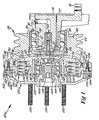
Figure 1 is a cross-sectional view of a rotational control apparatus constructed in accordance with a first preferred embodiment of the present invention; and -
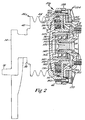
Figure 2 is a cross-sectional view of a rotational control apparatus constructed in accordance with a second preferred embodiment of the invention. - It should be noted that all the figures are drawn for ease of explanation of the basic teachings of the present invention only; the extensions of the figures with respect to number, position, relationship and dimensions of the parts to form the preferred embodiment will be explained or will be within the skill of the art after the following teachings of the present invention have been read and understood.
- Furthermore, when the terms "first", "second", "inner", "outer", "radially", "axially", and similar terms are used herein, its should be understood that these terms have reference only to the structure shown in the drawings as it would appear to a person viewing the drawings and are utilized only to facilitate describing the invention.
- With initial reference to
Figure 1 , a rotational control apparatus constructed in accordance with a first preferred embodiment according to the teachings of the invention is generally designated 10. In the most preferred form of the invention, rotational control apparatus 10 constitutes a friction clutch which is particularly adapted for use in driving a fan, such as a cooling fan used in an automotive environment. However, as it will become fully evident from reading and understanding the invention as detailed below, various aspects of the invention can be advantageously used outside this specific field, such as in the art of braking devices. - As depicted in this figure, rotational control apparatus 10 includes an integrally formed, generally L-
shaped journal bracket 14 that defines a support mount for the overall apparatus.Journal bracket 14 includes aflange portion 16 through which a plurality of bolts (not shown) are adapted to extend for threadably securingjournal bracket 14 in a fixed position to supporting structure (not shown), such as an engine block.Journal bracket 14 includes a shaft portion 22 that is adapted to support a sheave 26. In accordance with the preferred form according to the preferred teachings of the invention, sheave 26 constitutes a first or input member of rotational control apparatus 10 and is rotatably supported upon shaft portion 22 by means of a first bearing unit 30. More specifically, first bearing unit 30 includes inner and outer races which are press-fit upon shaft portion 22 and against sheave 26 respectively. The inner race(s) of first bearing unit 30 is axially fixed upon shaft portion 22 by abutting a shoulder 32 of shaft portion 22 at one axial position and, at a spaced axial position, through engagement with a retainer element 34 which is threadably attached to a reduced diametric, inner axial end 36 of shaft portion 22. - Sheave 26 is provided with a
shoulder 38 which axially locates sheave 26 relative to first bearing unit 30. In the preferred embodiment shown,shoulder 38 represents an extension of a first orhub portion 42 of sheave 26.First portion 42 defines an outer radial groovedsection 44 about which a belt (not shown) is adapted to extend for inputting a rotational driving force to sheave 26. Sheave 26 also includes a second portion 46 which is axially spaced fromfirst portion 42. With this arrangement, sheave 26 has associated therewith an inner radial diametric surface 48 and an outer radialdiametric surface 50, both of which are located within the confines of the sheave 26. - In the most preferred form of the invention, rotational control apparatus 10 constitutes a fluid pressure controlled device. In this preferred form, rotational control apparatus 10 incorporates a
cap member 54 which extends across inner diametric surface 48. As clearly shown inFigure 1 ,cap member 54 also abuts the outer race of first bearing unit 30 and is maintained axially by means of asnap ring 56. Aseal 58 is interposed betweencap member 54 and sheave 26. At the center ofcap member 54, a fluid passage defining coupling 62 is threadably secured. The passage of coupling 62 is in fluid communication with a conduit 66 of a rotary joint 68. Rotary joint 68 is mounted within a bore 70 formed in shaft portion 22 ofbracket 14. In general, rotary joint 68 takes the form of a cartridge that is known in the art and therefore will not be detailed here. However, it should be noted that conduit 66 is in further fluid communication with a passage 72 formed in shaft portion 22. Therefore, with this arrangement, a supply of pressurized fluid can be forced to selectively flow throughcap member 54 through passage 72, rotary joint 68 and coupling 62. - During initial assembly of rotational control apparatus 10, first bearing unit 30 is initially positioned against
shoulder 38 within sheave 26. Thereafter, sheave 26 and first bearing unit 30 are slid onto shaft portion 22 ofjournal bracket 14 until first bearing unit 30 abuts shoulder 32. Next, retainer element 34 is threaded onto the axial end 36 of shaft portion 22 which presses the inner race of first bearing unit 30 against shoulder 32. Rotary joint 68 can actually be installed before or after the assembly of sheave 26 and first bearing unit 30 uponjournal bracket 14. Withseal 58 and coupling 62 attached to capmember 54,cap member 54 is slid along inner radial diametric surface 48 and pressed against the outer race of first bearing unit 30. Thereafter,snap ring 56 is mounted in an annular groove formed in diametric surface 48 to axially retaincap member 54. With this arrangement,journal bracket 14 can be advantageously formed of one piece to enhance the structural characteristics thereof while still having shaft portion 22 extend well into sheave 26. In the preferred form, the fluid passage of coupling 62 is threaded for receipt of a bolt or the like to allow removal of cap member 54 (after removal of snap ring 56) for dissassembly. - In the most preferred form of the invention, retainer element 34 is formed with a weep hole 75 and shaft portion 22 is provided with a weep passage 77 that extends from the weep hole 75 axially through
journal bracket 14. With this preferred construction, if any leakage occurs between coupling 62 and rotary joint 68, the fluid will escape through the weep circuit and not through first bearing unit 30 to extend the useful life of bearing unit 30. - Rotational control apparatus 10 further includes a piston 76 having a disc-shaped portion defined, at least in part, by a first
axial side surface 80 that is exposed to the pressurized fluid flowing through coupling 62. Piston 76 also includes a second axial side surface 82 from which project outer and inner axially extendingportions seal 90 is interposed between outer axially extendingportion 86 andsurface 50 of second portion 46 of sheave 26 such that afluid chamber 92 is defined within sheave 26, which is preferably formed of a low porosity metal such as steel or iron and, more specifically, betweencap member 54, portions of sheave 26 and firstaxial side surface 80 of piston 76. As will be detailed further below, piston 76 is adapted to be selectively shifted axially relative to sheave 26 in order to engage and disengage rotational control apparatus 10. - In the preferred form of the invention, seal 90 is fixed to sheave 26. More specifically, an axially extending
annular projection 94 of a reaction plate 96 compresses seal 90 against sheave 26. Of course, it should be readily recognized that, while accommodating some axial movement ofseal 90,seal 90 could be carried by piston 76 itself and engagesurface 50. In any event, piston 76 is slidable along axial surfaces ofprojection 94,seal 90 and second portion 46 of sheave 26.Seal 90 preferably takes the form of a multi-cup seal and is positioned at an outermost portion offluid chamber 92 such that viscous fluids, such as grease or other lubricants, will tend to flow radially outwardly during operation of rotational control apparatus 10 and batheseal 90. Reaction plate 96 includes an outermost circumferential flange portion 100 that is adapted to be axially bolted to second portion 46 of sheave 26. More specifically, africtional lining 102 that defines a first frictional engagement surface of rotational control apparatus 10 receives buttonhead cap screws 104 that also extend through flange portion 100 and which are threadably received within second portion 46 of sheave 26. Therefore, the tightening ofscrews 104 securefrictional lining 102 and reaction plate 96 to sheave 26, as well as securely retainingannular seal 90 in a desired position. - Reaction plate 96 includes an inner, axially extending,
annular portion 108 which is provided with a dust seal 110 and aids in defining a plurality of annularly spacedcavities 112. In the preferred embodiment, twelvesuch cavities 112 are equally, annularly spaced in reaction plate 96 and the walls of thecavities 112 define ribs which structurally reinforce reaction plate 96. Each of thecavities 112 is adapted to receive acompression spring 116 which extends between reaction plate 96 and secondaxial side surface 82 of piston 76. Due to the presence ofsprings 116, piston 76 is biased towards shaft portion 22, but fluid pressure delivered intofluid chamber 92 through passage 72, rotary joint 68 and fluid passage defining coupling 62 can cause piston 76 to shift relative to sheave 26 against the biasing force ofsprings 116. During this axial shifting, piston 76 also slides relative to reaction plate 96, with inner axially extendingportion 88 of piston 76 being guided along inner axially extendingportion 108 of reaction plate 96. In the most preferred form of the invention, this interface between piston 76 and reaction plate 96 is provided with a friction reducing, thermal, spray applied, ceramic/metallic coating which is TEFLON impregnated. Such an arrangement is considered advantageous over the use of a lubricant, e.g. grease, which would tend to work out into the friction surfaces and could affect the engagement/disengagement forces associated with rotational control apparatus 10. This may be of particular concern given the intended field of use of rotational control apparatus 10 and the fact that dust could easily stick to and get into any lubricant used. Also, the adjacent radial surfaces of piston 76 and reactor plate 96 are not machined along a radial plane but have a convolute shape to provide stress relief. - Rotational control apparatus 10 also includes a second,
output member 120 having a first, outerradial section 124 which is interconnected with a second, innerradial section 128. Firstradial section 124 has associated therewith a secondfrictional lining 132 that is arranged juxtaposedfrictional lining 102. In the most preferred form of the invention, secondfrictional lining 132 is constituted by a disc formed of steel or other hardened material and is placed in an insertion mold whensecond member 120 is formed. In this fashion, secondfrictional lining 132 andsecond member 120 become integral. In the most preferred form of the invention, secondfrictional lining 132 is preferably reverse L-shaped as shown inFigure 1 which aids in holding the lining 132 in place. Secondfrictional lining 132 is also preferably formed with various radiallyconcentric teeth 133 to enhance the heat transfer from secondfrictional lining 132 tosecond member 120, as well as increasing the adhesion area between the two components. The disc-shapedlining 132 can also be provided withvarious bores 134 which open on the side ofsecond member 120 in order to enable the material forsecond member 120 to flow therein during the molding/casting process. Therefore, bores 134 will create pegs to prevent relative rotation between lining 132 andsecond member 120. Although friction lining 132 is preferably made of steel or iron,second member 120 is preferably formed from aluminum so as to be lightweight and to be easy to fabricate and machine, as well as for inertia, overall weight and reduced wear purposes. For similar reasons, piston 76 and reaction plate 96 are also preferably formed of aluminum. However, it should be appreciated that piston 76, reaction plate 96, and/orsecond member 120 could be formed as integral one piece castings of other material such as cast iron. - With this arrangement,
frictional linings Second member 120 is adapted to be mounted through the use of a threadedstub shaft 136 having ahead portion 142. More specifically, threadedstub shaft 136 is constituted by a jack bolt having a torque fitting and is adapted to be threadably received within a mountinghub 144 defined at a central portion of innerradial section 128. Mountinghub 144 is preferably formed integral with a cast-insteel insert 143 which actually is threadably attached tostub shaft 136. Mountinghub 144 is also provided with ashoulder 145 against which is positioned an inner race of asecond bearing unit 146.Second bearing unit 146 has an outer race which is press fit against a thermalexpansion controlling insert 147 cast integral with piston 76 and abuts piston 76 in one axial direction, with the outer race being retained in its desired position by means of asnap ring 148. - During a subsequent stage of assembly of rotational control apparatus 10, piston 76 is inserted into second portion 46 of sheave 26 and then reaction plate 96, with
springs 116 positioned withincavities 112, is secured to sheave 26 by means ofscrews 104. Withstub shaft 136 extending throughsecond bearing unit 146,second bearing unit 146 is press fit withininsert 147 and abuts piston 76. Thereafter,snap ring 148 is inserted to axially maintain the outer race ofsecond bearing unit 146. Mainly due to the construction of reaction plate 96, it should be realized thatsecond bearing unit 146 could be attached to piston 76 prior to the insertion of piston 76 within sheave 26 as well. Next,second member 120 is inserted within bearingunit 146. Thereafter, torque is applied tostub shaft 136 to rotate the same and drawsecond member 120 intosecond bearing unit 146 untilshoulder 145 abuts the inner race ofsecond bearing unit 146. In tightening of threadedstub shaft 136 in mountinghub 144,head portion 142 engages the inner race ofsecond bearing unit 146 such that the inner race is retained betweenhead portion 142 andshoulder 145. Due to this mounting arrangement and the presence ofsecond bearing unit 146, piston 76 andsecond member 120 are permitted to rotate relative to one another. In addition, sincesecond bearing unit 146 is located at an inner radial location, contaminants and friction lining dust will tend to flow radially outwardly and away fromsecond bearing unit 146 due to centrifugal forces created during operation of rotational control apparatus 10. Also provided onsecond member 120, at secondradial section 128, are a plurality of annularly spaced threaded shafts orstuds 150 which are preferably bonded withinsecond member 120. Since rotational control apparatus 10, in the most preferred form of the invention, constitutes a frictional fan clutch, threadedshafts 150 are adapted to mountingly receive a fan blade ring that is to be secured tosecond member 120. - With this construction,
first portion 42 of sheave 26 is adapted to be driven in a rotational manner relative tojournal bracket 14. The driving of sheave 26 also causes rotation of reaction plate 96 and firstfrictional lining 102. In addition, although there is no spline connection between piston 76 and reaction plate 96 or sheave 26, piston 76 will generally be caused to rotate in unison with these components due to the arrangement and mounting ofsprings 116. However, it should be recognized that there is permitted at least partial relative rotation between piston 76 and both sheave 26 and reaction plate 96 and thatsecond bearing unit 146 accommodates relative rotation between piston 76 andsecond member 120. - When used as a clutch wherein both sheave 26 and
second member 120 are permitted to rotate, springs 116 bias piston 76 into a position which causes engagement between the first and second frictional engagement surfaces defined byfrictional linings fluid chamber 92 to cause axial shifting of piston 76. Due to the interengagement between piston 76 andsecond member 120 throughsecond bearing unit 146, axial shifting of piston 76 relative to sheave 26 will cause concurrent axial shifting ofsecond member 120. This axial shifting ofsecond member 120 will cause disengagement betweenfrictional linings - At this point, it should be noted that first
axial side surface 80 of piston 76 is disc-shaped, i.e., non-annular, and has a substantial radial dimension, i.e., a dimension greater than the diameter offirst portion 42 of sheave 26. This construction establishes a large piston area which is acted upon by the pressurized fluid introduced intofluid chamber 92. Therefore, this large piston area enables a high disengagement force to be developed within rotational control apparatus 10 for a given fluid pressure, while also allowing a large amount of spring force to cause rapid engagement with reduced slipping and wear. - In the most preferred form of the invention, air is utilized as the fluid pressurized source. However, it should be readily recognized that other fluids could be utilized, including hydraulic fluid. In addition, other types of actuation systems could also be readily incorporated, including mechanical and eddy-current type actuation systems known in the art, without departing from the invention. In the case of an eddy-current actuation system, magnets could simply be provided on reaction plate 96, such as
opposite springs 116, to cooperate with a drive ring onsecond member 120. In any event, it is merely important to note that springs 116 and the fluid or other piston shifting system functions to axially shift piston 76 relative to sheave 26 so as to cause selective disengagement between sheave 26 andsecond member 120 in this form of the invention. Therefore, if pressure was lost, rotational control apparatus 10 would assume a fail-safe, engagement mode. - When sheave 26 and
second member 120 are engaged, the transfer of forces occurs at the outer radial portions of rotational control apparatus 10. More specifically, these forces are directly transferred between sheave 26 andsecond member 120 throughfrictional linings second bearing unit 146 does not get excessively loaded during operation of rotational control apparatus 10 such that an extended useful life ofsecond bearing unit 146 can be realized. - At this point, it should be also realized that the rotational control apparatus 10 of the present invention could also function as a braking device such as if threaded
shafts 150 or other commensurate structure are utilized to securesecond member 120 against rotation. However, the fixing ofsecond member 120 through threadedshafts 150 would still need to accommodate the axial shifting thereof in unison with piston 76. With such an arrangement, engagement betweenfrictional linings second member 120 could be selectively interconnected through other structure besides thefrictional linings - In the embodiment of
Figure 1 , springs 116 bias piston 76 into a position which causes engagement betweenfrictional linings Figure 2 represents an alternative embodiment which is constructed substantially identical to that of the first embodiment, but wherein correspondingsprings 116 are utilized to bias the rotational control apparatus 10a to a disengaged position. In accordance with this embodiment, a mounting ring 154 is secured to sheave 26 with a corresponding reaction plate 96a therebetween. Mounting ring 154 is formed with a pair of axially spaced and radially extendingportions Portion 158 actually receivesbolts 160 for interconnecting sheave 26, reaction plate 96a and mounting ring 154 together. On the other hand, radially extendingportion 159 of mounting ring 154 actually defines the first frictional engagement surface for the rotational control apparatus 10a of this embodiment. A corresponding second member 120a is provided with a radial flange 164 that becomes positioned in an undercut area generally defined byportion 159 of mounting ring 154. Radial flange 164 carries africtional lining 165 that is adapted to engageportion 159 of mounting ring 154 in order to interconnect sheave 26 and second member 120a. - Due to the positioning of radial flange 164 between sheave 26 and
portion 159 of mounting ring 154, springs 116 bias piston 76a in a direction which tends to disengage sheave 26 from second member 120a. In order to provide a more compact arrangement, piston 76a is provided with the cavities 112a for therespective springs 116 and reaction plate 96a is provided with astraight bearing surface 168 against which springs 116 act. - Except for the minor differences noted above, the embodiment of
Figure 2 is generally commensurate with that of the embodiment ofFigure 1 . However, due to the presence of mounting ring 154 and the arrangement of radial flange 164, springs 116 actually bias the rotational control apparatus 10a to a disengaged position by causing a concurrent axial shifting of piston 76a and second member 120a. The introduction of pressurized fluid intofluid chamber 92 will cause piston 76a and second member 120a to simultaneously shift, thereby causing sheave 26 to be interconnected with second member 120a. For the sake of completeness, mounting ring 154 can be provided with a plurality of annularly spacedfins 170 for heat dissipation and strength purposes and corresponding fins (not labeled) can be provided incap member 54 and in the embodiment ofFigure 1 such as along the axially sloping, outer portion ofsecond member 120. - Now that the basic teachings of the present invention have been explained, many extensions and variations would be obvious to one having ordinary skill in the art. For example, as indicated above, although the present invention has been explained with respect to a friction clutch, it should be appreciated that the teachings may apply to other types of torque transfer and/or rotational control apparatus such as brakes. Further, although rotational control apparatus 10 and 10a of the most preferred forms include several unique features which are believed to produce synergistic results, such features could be utilized separately or in other combinations.
- In general, the structural features of the present invention are provided to extend the useful life of the device. Because of the lack of axial loads placed on the bearing units and the exclusion of high wear items such as splines, rotational control apparatus is substantially maintenance free. When used as a vehicle fan clutch, the rotational control apparatus is expected to last well beyond the full life of the vehicle.
- Regardless of its particular use, the invention disclosed herein may be embodied in other specific forms without departing from the spirit or generally characteristics thereof and the embodiments described herein are to be considered in all respects illustrative and not restrictive. Instead, the scope of the invention is to be indicated by the appended claims, rather than by the foregoing description, and all changes which come within the meaning and range of equivalency of the claims are intended to be embraced therein.
Claims (19)
- Splineless rotational control apparatus comprising in combination:- a support mount (14) including a flange portion (16) adapted to receive bolts therethrough for securing the support mount in a fixed position to a support structure, with the support mount including a shaft portion (22) having an outer surface and a first fluid passage (72) therein;- a first member (26) including a first portion (42) formed as a hub adapted to be interconnected to a driving source and a second portion (46) axially spaced from the first portion (42);- a second member (120, 120a) having first (124) and second (128) sections, with the second section (128) extending radially inwardly from the first section and being axially spaced from the first portion (42) of the first member (26) a part of the second member being formed as a central mounting hub (144);- a piston (76, 76a) positioned axially between the first portion (42) of the first member (26) and the second section (128) of the second member (120,120a), with the piston being axially shiftable relative to the first member (26);- at least one spring (116) interposed between the first member (26) and the piston (76);- a first bearing unit (30) interposed between the support mount and the first member, with the first member being rotatably supported by the support mount through the first bearing unit, wherein the first bearing unit includes an outer race having an outer diameter dimensioned substantially equal to the inner diametric surface of the hub (42) and an inner race slidably received and retained on the outer surface of the shaft portion (22) and ;- a second bearing unit (146) interconnecting the piston and the second member for concurrent axial movement relative to the first member (26) while permitting relative rotation between the piston (76,76a) and the second member (120,120a); characterized by- a first frictional engagement surface (102,159) provided at the second portion of the first member for concurrent rotation with the first member;- a second frictional engagement surface (132,165) provided at the first section of the second member (120,120a) for concurrent rotation with the second member (120,120a);- and means for axially shifting the piston (76) relative to the first member (26) to cause selective engagement between the first (102,159) and second (132,165) engagement surfaces when the piston (76,76a) is axially shifted to selectively interconnect the first (26) and second members (120,120a).
- Splineless rotational control apparatus according to claim 1 in which the piston (76,76a) includes a radial portion (80) and an inner axially extending portion (88), with the axially extending portion of the first member (26) slidably supporting the axially extending portion (88) of the piston (76).
- Splineless rotational control apparatus according to claim 1 or 2 in which the second bearing unit (146) is interposed between the inner axially extending portion (88) of the piston (76) and the mounting hub (144) of the second member (120,120a), with the second bearing unit (146) being attached to and interconnecting each of the piston (76) and the second member (120,120a).
- Splineless rotationnal apparatus according to anyone of claims 1 to 3 in which the first bearing unit (30) is interposed between the support mount (14) and the first member (26), the first member being rotatably supported by the support mount (14) through the first bearing unit (30).
- Splineless rotational control apparatus according to anyone of claims 1 to 4 further comprising a cap member (54) sealingly engaging the first portion (42) of the first member (26), with the cap member (54), the piston (76) and the first member (26) defining a fluid chamber (92), said cap member (54) being attached to the first member (26) and arranged between the first bearing unit (30) and the piston (76), with the cap member having a second fluid passage (62) an outer diameter dimensioned substantially equal to the inner diametric surface of the hub (42), with the outer race being positioned against the inner diametric surface of the hub (42) and axially captured within the hub (42) by the cap member (54), with the hub, outer race and cap member (54) being rotatable in unison relative to the shaft portion (22).
- The splineless rotational control apparatus according to claim 5 further comprising a rotary joint (68) mounted between the cap (54) member and the shaft portion (22), with the rotary joint (68) including a conduit (66) which fluidly interconnects the first (72) and second (62) fluid passages while enabling concurrent rotation of the hub (42), the outer race and the cap member (54) relative to the shaft portion (22);
- Splineless rotational control apparatus according to anyone of claim 1 to 6 in which the radial portion (80) of the piston (76) is disc-shaped and non-annular.
- Splineless rotational control apparatus according to anyone of claim 1 to 7 further comprising a jack bolt (136) extending through the bearing unit (146) and being threadably secured to the mounting hub (144) of the second member (120,120a).
- Splineless rotational control apparatus according to claim 8 wherein the mounting hub (144) includes a central threaded opening for threadable receipt of said jack bolt (136), with the second bearing unit (146) being sandwiched between the jack bolt (136) and the mounting hub (144).
- Splineless rotational control apparatus according to anyone of claims 2 to 9 in which said support mount is a journal (14) and the first bearing unit (30) is interposed between the shaft portion (22) and the first member (26) for rotatably supporting the first member on the journal (14).
- Splineless rotational control apparatus according to anyone of claims 1 to 10 wherein the piston (76,76a) sealingly engages the second portion (46) of the first member (26).
- Splineless rotational control apparatus according to any one of claim 1 to 11 further comprising a reaction plate (96,96a) including an outer radial portion fixed to the second portion of the first member (26) and an inner radial portion.
- Splineless rotational control apparatus according to claim 12 wherein the piston (76,76a) includes an axial section positioned in slidable relationship with the inner radial portion of the reaction plate (96,96a).
- Splineless rotational control apparatus according to claim 12 or claim 13 further comprising a plurality of annularly spaced cavities (112) formed in the reaction plate (96), with each of the cavities (112) being adapted to receive a respective spring (116).
- Splineless rotational control apparatus according to claim 12 or claim 13 wherein said spring (116) is interposed between the reaction plate (96a) and the piston (76a).
- Splineless rotational apparatus according to anyone of claims 1 to 15 further comprising a retainer element (34) secured to the shaft portion (22) and abutting the inner race of the bearing unit (30) for axially fixing the inner race relative to the support mount.
- Splineless rotational apparatus according to claim 16 further comprising a weep hole (75) extending through the retainer element (34).
- Splineless rotational control apparatus according to anyone of claims 1 to 17 wherein the spring (116) moves the piston (76) to cause engagement between the first (102) and second (132) engagement surfaces.
- Splineless rotational control apparatus according to anyone of claims 1 to 17 wherein the spring (116) moves the piston (76a) to cause disengagement of the second (165) engagement surface from the first (159) engagement surface.
Applications Claiming Priority (1)
| Application Number | Priority Date | Filing Date | Title |
|---|---|---|---|
| PCT/US1999/010866 WO2000070236A2 (en) | 1998-03-05 | 1999-05-17 | Rotational control apparatus |
Publications (2)
| Publication Number | Publication Date |
|---|---|
| EP1185799A2 EP1185799A2 (en) | 2002-03-13 |
| EP1185799B1 true EP1185799B1 (en) | 2011-12-07 |
Family
ID=22272773
Family Applications (1)
| Application Number | Title | Priority Date | Filing Date |
|---|---|---|---|
| EP99923153A Expired - Lifetime EP1185799B1 (en) | 1999-05-17 | 1999-05-17 | Rotational control apparatus |
Country Status (8)
| Country | Link |
|---|---|
| EP (1) | EP1185799B1 (en) |
| JP (1) | JP3881519B2 (en) |
| KR (1) | KR100551541B1 (en) |
| CN (1) | CN1316175C (en) |
| AT (1) | ATE536491T1 (en) |
| AU (1) | AU2003266752B2 (en) |
| CA (1) | CA2373216C (en) |
| MX (1) | MXPA01011918A (en) |
Families Citing this family (3)
| Publication number | Priority date | Publication date | Assignee | Title |
|---|---|---|---|---|
| US6838796B1 (en) * | 2003-08-05 | 2005-01-04 | Horton, Inc. | Two-speed rotational control apparatus with eddy current drive |
| CN108050171B (en) * | 2018-01-22 | 2023-10-20 | 四川远星橡胶有限责任公司 | A pneumatically controlled clutch with adjustable output torque |
| CN109973543A (en) * | 2019-02-18 | 2019-07-05 | 芜湖市中亚汽车制动元件有限公司 | With dust-proof and sealing device end face zigzag clutch |
Family Cites Families (5)
| Publication number | Priority date | Publication date | Assignee | Title |
|---|---|---|---|---|
| US4427102A (en) * | 1981-07-06 | 1984-01-24 | Horton Industries, Inc. | Fluid engaged and spring returned fan clutch |
| US4541516A (en) * | 1983-03-09 | 1985-09-17 | Allied Corporation | Clutch drive with antirotation spring |
| US4589535A (en) * | 1984-09-17 | 1986-05-20 | Allied Corporation | Fan clutch with replaceable plate carrier member |
| US4657126A (en) * | 1985-02-25 | 1987-04-14 | Horton Manufacturing Co., Inc. | Two-speed clutch |
| US5398794A (en) * | 1993-06-02 | 1995-03-21 | Horton Industries, Inc. | Overheating protection device for rotational control apparatus |
-
1999
- 1999-05-17 CN CNB998167223A patent/CN1316175C/en not_active Expired - Fee Related
- 1999-05-17 MX MXPA01011918A patent/MXPA01011918A/en active IP Right Grant
- 1999-05-17 KR KR1020017014625A patent/KR100551541B1/en not_active Expired - Fee Related
- 1999-05-17 EP EP99923153A patent/EP1185799B1/en not_active Expired - Lifetime
- 1999-05-17 JP JP2000618627A patent/JP3881519B2/en not_active Expired - Lifetime
- 1999-05-17 CA CA002373216A patent/CA2373216C/en not_active Expired - Fee Related
- 1999-05-17 AT AT99923153T patent/ATE536491T1/en active
-
2003
- 2003-12-05 AU AU2003266752A patent/AU2003266752B2/en not_active Ceased
Also Published As
| Publication number | Publication date |
|---|---|
| JP2002544456A (en) | 2002-12-24 |
| AU2003266752B2 (en) | 2006-11-30 |
| CA2373216A1 (en) | 2000-11-23 |
| EP1185799A2 (en) | 2002-03-13 |
| CA2373216C (en) | 2007-05-08 |
| KR20020022664A (en) | 2002-03-27 |
| MXPA01011918A (en) | 2003-09-04 |
| ATE536491T1 (en) | 2011-12-15 |
| HK1056006A1 (en) | 2004-01-30 |
| CN1316175C (en) | 2007-05-16 |
| CN1443286A (en) | 2003-09-17 |
| AU2003266752A1 (en) | 2004-01-15 |
| KR100551541B1 (en) | 2006-02-13 |
| JP3881519B2 (en) | 2007-02-14 |
Similar Documents
| Publication | Publication Date | Title |
|---|---|---|
| EP0718520B1 (en) | Wet clutch assembly | |
| KR100551766B1 (en) | Multi-Disk Friction Device Having Forced Lubrication on Demand | |
| US6092638A (en) | Splineless rotational control apparatus | |
| CA1302918C (en) | Variable speed drive for engine cooling fans | |
| KR100561174B1 (en) | Automatic Transmission having Grounded Clutch with Convergent Cooling | |
| EP1081401A2 (en) | Multi-disk device having forced lubrication on demand | |
| US5611415A (en) | Rotational control apparatus | |
| AU2004300987B2 (en) | Two-speed rotational control apparatus with eddy current drive | |
| EP0513082B1 (en) | Rotational control apparatus | |
| US7591349B2 (en) | Liquid cooled brake assembly | |
| CA2373216C (en) | Splineless rotational control apparatus | |
| US6874610B2 (en) | Compact dry power takeoff unit | |
| US2818949A (en) | Brake-clutch construction | |
| JP4478129B2 (en) | Rotation control device without spline | |
| US20040031659A1 (en) | Rotational control apparatus | |
| US4606447A (en) | Coupling clutch and a self-contained, non-removable guard | |
| HK1056006B (en) | Splineless rotational control apparatus | |
| US6786313B2 (en) | Rotational control apparatus | |
| KR970006364B1 (en) | Disc Adapters for Power Transmission and Shutdown | |
| JPH10176722A (en) | Friction connecting member | |
| CS231740B1 (en) | Device for controlling the friction clutch of the cooling fan of internal combustion engines |
Legal Events
| Date | Code | Title | Description |
|---|---|---|---|
| PUAI | Public reference made under article 153(3) epc to a published international application that has entered the european phase |
Free format text: ORIGINAL CODE: 0009012 |
|
| AK | Designated contracting states |
Kind code of ref document: A2 Designated state(s): AT BE CH CY DE DK ES FI FR GB GR IE IT LI LU MC NL PT SE |
|
| AX | Request for extension of the european patent |
Free format text: AL PAYMENT 20011217;LT PAYMENT 20011217;LV PAYMENT 20011217;MK PAYMENT 20011217;RO PAYMENT 20011217;SI PAYMENT 20011217 |
|
| 17P | Request for examination filed |
Effective date: 20011217 |
|
| RAP1 | Party data changed (applicant data changed or rights of an application transferred) |
Owner name: HORTON INC. |
|
| 17Q | First examination report despatched |
Effective date: 20040714 |
|
| 17Q | First examination report despatched |
Effective date: 20040714 |
|
| APBK | Appeal reference recorded |
Free format text: ORIGINAL CODE: EPIDOSNREFNE |
|
| APBN | Date of receipt of notice of appeal recorded |
Free format text: ORIGINAL CODE: EPIDOSNNOA2E |
|
| APBR | Date of receipt of statement of grounds of appeal recorded |
Free format text: ORIGINAL CODE: EPIDOSNNOA3E |
|
| APBV | Interlocutory revision of appeal recorded |
Free format text: ORIGINAL CODE: EPIDOSNIRAPE |
|
| GRAP | Despatch of communication of intention to grant a patent |
Free format text: ORIGINAL CODE: EPIDOSNIGR1 |
|
| GRAS | Grant fee paid |
Free format text: ORIGINAL CODE: EPIDOSNIGR3 |
|
| GRAA | (expected) grant |
Free format text: ORIGINAL CODE: 0009210 |
|
| AK | Designated contracting states |
Kind code of ref document: B1 Designated state(s): AT BE CH CY DE DK ES FI FR GB GR IE IT LI LU MC NL PT SE |
|
| AX | Request for extension of the european patent |
Extension state: AL LT LV MK RO SI |
|
| REG | Reference to a national code |
Ref country code: GB Ref legal event code: FG4D |
|
| REG | Reference to a national code |
Ref country code: CH Ref legal event code: EP |
|
| REG | Reference to a national code |
Ref country code: IE Ref legal event code: FG4D |
|
| REG | Reference to a national code |
Ref country code: DE Ref legal event code: R096 Ref document number: 69943910 Country of ref document: DE Effective date: 20120202 |
|
| REG | Reference to a national code |
Ref country code: NL Ref legal event code: VDEP Effective date: 20111207 |
|
| LTLA | Lt: lapse of european patent or patent extension | ||
| PG25 | Lapsed in a contracting state [announced via postgrant information from national office to epo] |
Ref country code: NL Free format text: LAPSE BECAUSE OF FAILURE TO SUBMIT A TRANSLATION OF THE DESCRIPTION OR TO PAY THE FEE WITHIN THE PRESCRIBED TIME-LIMIT Effective date: 20111207 Ref country code: GR Free format text: LAPSE BECAUSE OF FAILURE TO SUBMIT A TRANSLATION OF THE DESCRIPTION OR TO PAY THE FEE WITHIN THE PRESCRIBED TIME-LIMIT Effective date: 20120308 Ref country code: SE Free format text: LAPSE BECAUSE OF FAILURE TO SUBMIT A TRANSLATION OF THE DESCRIPTION OR TO PAY THE FEE WITHIN THE PRESCRIBED TIME-LIMIT Effective date: 20111207 |
|
| PG25 | Lapsed in a contracting state [announced via postgrant information from national office to epo] |
Ref country code: CY Free format text: LAPSE BECAUSE OF FAILURE TO SUBMIT A TRANSLATION OF THE DESCRIPTION OR TO PAY THE FEE WITHIN THE PRESCRIBED TIME-LIMIT Effective date: 20111207 Ref country code: BE Free format text: LAPSE BECAUSE OF FAILURE TO SUBMIT A TRANSLATION OF THE DESCRIPTION OR TO PAY THE FEE WITHIN THE PRESCRIBED TIME-LIMIT Effective date: 20111207 |
|
| PG25 | Lapsed in a contracting state [announced via postgrant information from national office to epo] |
Ref country code: PT Free format text: LAPSE BECAUSE OF FAILURE TO SUBMIT A TRANSLATION OF THE DESCRIPTION OR TO PAY THE FEE WITHIN THE PRESCRIBED TIME-LIMIT Effective date: 20120409 |
|
| REG | Reference to a national code |
Ref country code: AT Ref legal event code: MK05 Ref document number: 536491 Country of ref document: AT Kind code of ref document: T Effective date: 20111207 |
|
| PLBE | No opposition filed within time limit |
Free format text: ORIGINAL CODE: 0009261 |
|
| STAA | Information on the status of an ep patent application or granted ep patent |
Free format text: STATUS: NO OPPOSITION FILED WITHIN TIME LIMIT |
|
| PG25 | Lapsed in a contracting state [announced via postgrant information from national office to epo] |
Ref country code: DK Free format text: LAPSE BECAUSE OF FAILURE TO SUBMIT A TRANSLATION OF THE DESCRIPTION OR TO PAY THE FEE WITHIN THE PRESCRIBED TIME-LIMIT Effective date: 20111207 |
|
| 26N | No opposition filed |
Effective date: 20120910 |
|
| PG25 | Lapsed in a contracting state [announced via postgrant information from national office to epo] |
Ref country code: IT Free format text: LAPSE BECAUSE OF FAILURE TO SUBMIT A TRANSLATION OF THE DESCRIPTION OR TO PAY THE FEE WITHIN THE PRESCRIBED TIME-LIMIT Effective date: 20111207 |
|
| PG25 | Lapsed in a contracting state [announced via postgrant information from national office to epo] |
Ref country code: MC Free format text: LAPSE BECAUSE OF NON-PAYMENT OF DUE FEES Effective date: 20120531 |
|
| REG | Reference to a national code |
Ref country code: CH Ref legal event code: PL |
|
| REG | Reference to a national code |
Ref country code: DE Ref legal event code: R097 Ref document number: 69943910 Country of ref document: DE Effective date: 20120910 |
|
| PG25 | Lapsed in a contracting state [announced via postgrant information from national office to epo] |
Ref country code: AT Free format text: LAPSE BECAUSE OF FAILURE TO SUBMIT A TRANSLATION OF THE DESCRIPTION OR TO PAY THE FEE WITHIN THE PRESCRIBED TIME-LIMIT Effective date: 20111207 Ref country code: CH Free format text: LAPSE BECAUSE OF NON-PAYMENT OF DUE FEES Effective date: 20120531 Ref country code: LI Free format text: LAPSE BECAUSE OF NON-PAYMENT OF DUE FEES Effective date: 20120531 |
|
| REG | Reference to a national code |
Ref country code: IE Ref legal event code: MM4A |
|
| REG | Reference to a national code |
Ref country code: FR Ref legal event code: ST Effective date: 20130131 |
|
| PG25 | Lapsed in a contracting state [announced via postgrant information from national office to epo] |
Ref country code: FR Free format text: LAPSE BECAUSE OF NON-PAYMENT OF DUE FEES Effective date: 20120531 Ref country code: ES Free format text: LAPSE BECAUSE OF FAILURE TO SUBMIT A TRANSLATION OF THE DESCRIPTION OR TO PAY THE FEE WITHIN THE PRESCRIBED TIME-LIMIT Effective date: 20120318 Ref country code: IE Free format text: LAPSE BECAUSE OF NON-PAYMENT OF DUE FEES Effective date: 20120517 |
|
| PG25 | Lapsed in a contracting state [announced via postgrant information from national office to epo] |
Ref country code: FI Free format text: LAPSE BECAUSE OF FAILURE TO SUBMIT A TRANSLATION OF THE DESCRIPTION OR TO PAY THE FEE WITHIN THE PRESCRIBED TIME-LIMIT Effective date: 20111207 |
|
| PG25 | Lapsed in a contracting state [announced via postgrant information from national office to epo] |
Ref country code: LU Free format text: LAPSE BECAUSE OF NON-PAYMENT OF DUE FEES Effective date: 20120517 |
|
| PGFP | Annual fee paid to national office [announced via postgrant information from national office to epo] |
Ref country code: DE Payment date: 20160524 Year of fee payment: 18 Ref country code: GB Payment date: 20160426 Year of fee payment: 18 |
|
| REG | Reference to a national code |
Ref country code: DE Ref legal event code: R119 Ref document number: 69943910 Country of ref document: DE |
|
| GBPC | Gb: european patent ceased through non-payment of renewal fee |
Effective date: 20170517 |
|
| PG25 | Lapsed in a contracting state [announced via postgrant information from national office to epo] |
Ref country code: GB Free format text: LAPSE BECAUSE OF NON-PAYMENT OF DUE FEES Effective date: 20170517 Ref country code: DE Free format text: LAPSE BECAUSE OF NON-PAYMENT OF DUE FEES Effective date: 20171201 |