EP1185476B1 - Process and apparatus for controlling the registration of converting operations with prints on a web - Google Patents
Process and apparatus for controlling the registration of converting operations with prints on a web Download PDFInfo
- Publication number
- EP1185476B1 EP1185476B1 EP00936291A EP00936291A EP1185476B1 EP 1185476 B1 EP1185476 B1 EP 1185476B1 EP 00936291 A EP00936291 A EP 00936291A EP 00936291 A EP00936291 A EP 00936291A EP 1185476 B1 EP1185476 B1 EP 1185476B1
- Authority
- EP
- European Patent Office
- Prior art keywords
- web
- signal
- indicia
- folding
- web speed
- Prior art date
- Legal status (The legal status is an assumption and is not a legal conclusion. Google has not performed a legal analysis and makes no representation as to the accuracy of the status listed.)
- Expired - Lifetime
Links
Images


Classifications
-
- B—PERFORMING OPERATIONS; TRANSPORTING
- B65—CONVEYING; PACKING; STORING; HANDLING THIN OR FILAMENTARY MATERIAL
- B65H—HANDLING THIN OR FILAMENTARY MATERIAL, e.g. SHEETS, WEBS, CABLES
- B65H23/00—Registering, tensioning, smoothing or guiding webs
- B65H23/04—Registering, tensioning, smoothing or guiding webs longitudinally
- B65H23/18—Registering, tensioning, smoothing or guiding webs longitudinally by controlling or regulating the web-advancing mechanism, e.g. mechanism acting on the running web
- B65H23/188—Registering, tensioning, smoothing or guiding webs longitudinally by controlling or regulating the web-advancing mechanism, e.g. mechanism acting on the running web in connection with running-web
- B65H23/1882—Registering, tensioning, smoothing or guiding webs longitudinally by controlling or regulating the web-advancing mechanism, e.g. mechanism acting on the running web in connection with running-web and controlling longitudinal register of web
-
- B—PERFORMING OPERATIONS; TRANSPORTING
- B65—CONVEYING; PACKING; STORING; HANDLING THIN OR FILAMENTARY MATERIAL
- B65H—HANDLING THIN OR FILAMENTARY MATERIAL, e.g. SHEETS, WEBS, CABLES
- B65H45/00—Folding thin material
- B65H45/02—Folding limp material without application of pressure to define or form crease lines
- B65H45/06—Folding webs
- B65H45/10—Folding webs transversely
Definitions
- the present invention relates to registration of indicia into a predetermined space on a paper web. Particularly, the present invention relates to controlling the location of the indicia during paper converting operations such as folding and cutting operations.
- Sheets for household use are well known in the art. It is often desired to decorate such sheets, such as by printing. Printing imparts an aesthetically pleasing pattern to the sheet. Alternatively, the sheet may be embossed to impart an aesthetically pleasing pattern which is also tactually discernible.
- Such sheets are typically made in continuous form, then later cut to discrete lengths as desired. Such cutting to discrete lengths may occur at the point of use, such as is caused by the consumer detaching one sheet from the balance thereof at a line of termination.
- the line of termination typically comprises a line of weakness, such as a perforation.
- the continuous sheet may be folded and cut into discrete portions prior to the point of use. Such an arrangement often occurs in individual napkins which are folded and cut during manufacture and purchased by the consumer as discrete units.
- a phasing device is necessary to ensure that a machine direction misalignment of the web caused by web slippage or stretching will not cause each of the indicia occurring after the slippage or stretching to be placed out of registry with the converting machinery.
- Significant misregistry between the web indicia and converting machinery results in scrap of succeeding portions of the web affected by the misregistry. Therefore, an accurate web phasing device is essential for any commercial high speed converting operation requiring indicia to be registered in the machine direction relative to the operation being performed.
- Such monitoring device is generally performed by a photoelectric scanning device, generally referred to in the industry as a photo eye unit which senses registration marks on the web associated with each indicia and generates an indicia reference signal.
- a photoelectric scanning device generally referred to in the industry as a photo eye unit which senses registration marks on the web associated with each indicia and generates an indicia reference signal.
- the photo eye unit would be positioned within the operating station and would sense a registration mark at exactly the time that the associated converting operation were being performed on the web.
- a reference signal generated by the converting operation would be input to a signal comparator along with the web indicia signal to determine the degree of misregistry between the web and the equipment performing the converting operation.
- the system would then compensate for the misregistry by adjusting the orientation of the converting equipment.
- Varying the speed of an in-line operation such as perforating or printing can be accomplished where the web speed is maintained by a set of nip rollers or a winding operation which pulls the web past the operation being performed.
- folding cylinders are typically the last operation in the process such that adjusting the rotation of the folding cylinders to maintain print registration requires concurrent adjustment in the web speed.
- the design may be feasible, the maintenance of such a complex system may render it impractical, particularly for high speed applications.
- a sensor for detecting misregistration of the indicia is placed a set distance upstream of the folding operation with a set of nip rolls interposed therebetween for controlling the speed of the web.
- a web speed control varies the rotational speed of the nip rolls increasing or decreasing the web speed to synchronize the registration of the indicia with fold lines produced by folding cylinders.
- the present invention provides a process for registering indicia with folds on a web.
- the process comprises providing a web having a series indicia successively spaced in a machine direction. As the web advances in the machine direction, the indicia are in juxtaposition to a photo sensor which detects the position of the registration marks relative to the rotation of a pair of folding cylinders.
- the pair of folding cylinders are spaced a predetermined distance in the machine direction from the photo sensor.
- the photo sensor is linked to a web speed control which adjust the rate of web movement in the machine direction in order to synchronize the location of registration marks relative to the folds produced by the folding cylinders.
- the web speed control comprises a signal comparator which receives first and second input signals.
- the first input signal is generated by the photo sensor detecting the position of the registration marks on the web.
- the second input signal is generated by a position resolver measuring the angular position of the folding cylinders.
- the signal comparator generates an error signal representing the misregistration of the indicia relative to the fold lines.
- the web speed is advanced or retarded via the nip rolls in order to continually reduce the error signal to zero.
- the web 12 according to the present invention is generally planar, soft and absorbent.
- the web 12 is suitable for use in applications, such as toilet tissue, paper toweling, placemats, napkins, etc.
- the web 12 is cellulosic, and preferably paper.
- the web 12 according to the present invention may be made according to commonly assigned U.S. Patents 4,191,609 issued March 4, 1980 to Trokhan; 4,637,859 issued January 20, 1987 to Trokhan; and 5,245,025 issued September 14, 1993 to Trokhan et al.
- the web 12 is preferably manufactured in a continuous process, then later cut into discrete units according to how the final product will be distributed to the consumer.
- Discrete units include roll products (such as paper toweling and bath tissue) and individual sheets (such as table napkins).
- the sheet 40 is presented to the consumer as an individually folded unit produced by a folding operation.
- the present invention may be equally applicable to various types of web folding and web chop-off operations, the application described hereunder is a folding operation utilizing pair of folding cylinders.
- Illustrated in Figures 1a and 1b is a converting operation 60 for folding and cutting a paper web 12 having indicia 45 disposed thereon.
- the indicia 45 may include registration marks.
- a feedback control system governs the location of the indicia 45 with respect to fold lines via variable speed nip rolls 28 which advance or retard the web speed while delivering the paper web 12 from a parent roll 16 to a folding table 30, and eventually a pair of folding cylinders 60a and 60b.
- the pair of folding cylinders 60a, 60b rotate at a constant angular velocity forming a continuous web stack 34 which is eventually cut in half producing two equal stacks of individually folded sheets 40.
- the output produced by most converting operations is a function of the web speed.
- web speed is set at a base speed by the surface speed of the folding cylinders 60a, 60b and advanced or retarded by the variable speed nip rolls 28.
- the web speed can be as low as about 1000 feet/minute (305 m/min), preferably the web speed can be as low as 500 feet/ minute (152 m/min), more preferably the web speed can be as low as about 100 feet/minute (30 m/min).
- the web speed can be as high as about 2000 feet/minute (610 m/min), preferably the web speed can be as high as about 2500 feet/minute (762 m/min), more preferably the web speed can be as high as about 3000 feet/minute (914 m/min).
- Advancing or retarding the web speed in order to accommodate registration of the indicia 45 with the folding operation may require adjustments to other equipment upstream of the folding operation.
- the web 12 is drawn from an unwind stand 14 comprising a parent roll.
- the parent roll is typically surface driven by an unwind stand motor.
- a dancer 18 connected to a feedback position sensor for the unwind stand motor governs the speed at which the parent roll 16 is unwound.
- the converting operation may include embossment rolls 20 between the unwind stand 14 and the folding equipment.
- the embossment rolls typically have an independent drive requiring a separate feedback control system for adjusting to the rapid changes in web speed induced by the variable speed nip rolls.
- Such feedback control system may include a load cell 22 which is an electronic device for measuring reaction forces at an idler bearing. The reaction forces can be used to measure the average tension in the web.
- the indicia 45 may be applied to the web 12 by any means known in the art suitable for applying spaced indicia 45 at predetermined repeating intervals.
- the indicia 45 may be aesthetically pleasing and printed, either in a single color or in a plurality of colors.
- the indicia 45 may be embossed or applied in a manner affecting inherent properties of the web 12 such as caliper, strength, softness etc.
- the equipment applying the indicia may be installed upstream of the folding equipment. Such equipment typically have independent drives requiring separate feedback control systems for accommodating adjustments in web speed.
- the indicia 45 are printed onto the web 12 from a rotatable cylinder.
- the rotatable cylinder is driven about a central axis at a predetermined angular velocity.
- Suitable printing processes known in the art include gravure printing and flexographic printing.
- a suitable apparatus for applying the indicia 45 to the substrate is disclosed in commonly assigned patent 5,213,037 issued May 25, 1993 to Leopardi, II.
- embossing technique well known in the art is suitable. Suitable embossing techniques include those described in commonly assigned U.S. Patents 3,414,459 issued December 3, 1968 to Wells; 3,556,907 issued January 19, 1971 to Nystraad; and 5,294,475 issued March 15, 1994 to McNeil.
- the indicia 45 may comprise known additives which increase the adhesion, softness, wet strength, temporary wet strength, hydrophobicity/hydrophilicity, or which functionally affects any other property of the web 12 may be applied thereto.
- a device which may be used in intermittent operation and suitable for applying functional indicia 45 to the web 12 is disclosed in commonly assigned U.S. Patent 5,143,776 issued September 1, 1992 to Givens.
- the web 12 Prior to folding, the web 12 is drawn along idler rollers by the variable speed nip rolls such that the longitudinal edges 47 of the web 12 are aligned with the MD.
- the web 12 is folded two times, first in the CD so that each of the longitudinal edges 47 is contiguous, producing a fold line running in the MD and second in the MD producing a fold line running in the CD.
- the folded web 12 is subsequently cut in half, parallel to the fold line running in the CD.
- the cutting operation divides the web 12 into individual folded sheets and forms the leading and trailing edges 46, 48 which are contiguous in the folded arrangement.
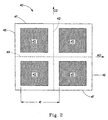
- each unfolded sheet comprises four quadrants defined by orthogonal fold lines running in the MD and the CD and the corresponding leading 46, trailing 48 and longitudinal edges 47.
- the indicia may be arranged in any repeating manner with respect to the quadrants.
- the Indicia 45 are disposed within each quadrant, juxtaposed with the CD fold line 42 and the corresponding leading 46 or trailing edge 48 of the sheet 40 and generally oriented in the CD within the X-Y plane of the sheet.
- the CD fold lines 42 are spaced from the indicia 45 a predetermined distance that is repeated in succession.
- the CD fold lines 42 are centered between two successive indicia 45 such that the distance between successive CD fold lines 42 is about equal to the design length 41. This results in a spaced relationship that is repeated throughout the folding process.
- the spaced relationship is maintained by a control system that monitors the registration of the indicia 45 relative to the folding operation and adjust the web speed to correct misregistration occurring between the indicia 45 and the CD fold lines 42.
- the folding operation may be accomplished by any suitable means for folding and cutting a continuous web 12 to form individual sheets having four quadrants defined by perpendicular fold lines.
- a folding board 30 which folds the web 12 in the CD bringing the longitudinal edges together in a face-to-face relationship producing MD fold lines.
- the folded web 12 is delivered to a pair of folding cylinders 60a, 60b which transversely fold the web 12 in the MD forming a continuous web stack 34 with CD fold lines 42 on opposite ends of the stack 34.
- a typical folding cylinder arrangement is depicted in Figure 3.
- the arrangement includes a pair of opposing, continuously turning cylinders 60a, 60b.
- Each cylinder 60a, 60b includes a folding knife 62a, 62b and a folding jaw 64a, 64b that pivots towards an anvil 66a, 66b.
- the folding knife 62a of one folding cylinder 60a enters between the folding jaw 64b and anvil 66b of the opposing folding cylinder 60b, pressing the web 12 into this intermediate space and guiding the web 12 up to the opening of the folding jaw 64b.
- the folding knife 62a Shortly before the completion of the closing movement of the folding jaw 64b, the folding knife 62a is guided out of this space and the web 12 is clamped between the folding jaw 64b and the anvil 66b and guided along the circumference of the continuously turning folding cylinder 60b until the folding jaw 64b opens and the folded web 12 is released. Concurrently, while the folding cylinder 60b releases the web 12, the folding knife 62b of the same cylinder 60b enters between the folding jaw 64a and anvil 64a of the opposing cylinder 60a pressing the web 12 therein and the and the process is repeated. This repetitive process proceeds forming a continuous web stack 34.
- a control system monitors the location of the indicia 45 relative to the placement of the CD fold lines 42.
- the web 12 travels in the machine direction over a series of idler rollers 24 in juxtaposition to an optic sensor 26 fixed a known distance upstream of the folding cylinders 60a, 60b.
- the optic sensor 26 detects the position of the indicia 45 on the web 12.
- the sensor 26 determines the difference in reflectance between the indicia 45 and the web 12.
- the indicia 45 may not provide adequate contrast with the web 12.
- a registration mark may be applied to the web 12 in register with the indicia.
- the registration mark may be included within the indicia 45 or it may be applied to the trim of the web 12. Trim refers to that portion of the web 12 at the outboard edges, and which is later removed from the portion of the sheet 40 which is presented to the consumer. Since the trim is not presented to the consumer, registration marks applied to the trim may be of any size and shape suitable for indicating its position to the sensing means.
- the registration mark 31 is printed onto the web 12 by the same printing plate used to print the indicia 45. In this manner the spacing of the registration mark relative to the indicia 45, or any part thereof, is known.
- the optic sensor 26 produces a first signal comprising real time pulses for every indicia 45 passing in juxtaposition to the sensor 26.
- the real time pulses represent the position of the indicia 45 with respect to time.
- the folding cylinders 60a, 60b are set at a constant angular velocity which establishes the base web speed.
- a position resolver 36 mounted on the folding cylinders 60a, 60b produces a second signal comprising a numerical value that repeats every rotation.
- the numerical values represent the angular position of the folding cylinders 60a, 60b at any point in time.
- a suitable position resolver 38 is available from the Reliance Electric Co. of Cleveland, Ohio as Model No. M/N 57C360 and is typically designated by the motor which drives the rotatable component from which the signal is taken.
- the resolver may be used in conjunction with a resolver input module, such as is available from Reliance Electric as Part No. M/N 57C411.
- an encoder can be substituted for the position resolver 36, provided one uses the appropriate control logic, as is well known in the art.
- a suitable position resolver 36 is capable of determining angular position within at least 0.1 degrees.
- a preferred position resolver has at least 4,096 distinct positions corresponding to a numerical value per rotation.
- the photo sensor 26 and the position resolver 36 are set up such that the real time pulses produced by the photo sensor are desired to coincide with a specific numerical value produced by the position resolver 36.
- the specific numerical value produced by the position resolver 36 indicates the angular position of the folding cylinders where the CD fold lines 42 are in register with the indicia. Misregistration between the indicia 45 (registration marks) and the CD fold lines 42 is measured and corrected via a web speed control 80.
- the web speed control 80 comprises a signal comparator 82 which activates a servo motor 84 coupled to the variable speed nip rolls 28.
- a suitable signal comparator 82 is a Reliance Electric Auto Max Processor Module comprising the resolver photo eyes and resolver input cards.
- the first and second signals are input to the signal comparator 82 which measures the pulses created by the first signal and the numerical value produced by the second signal to yield an error signal.
- the error signal is based on the difference between the actual numerical value of the second signal and the specific numerical value desired for the indicia to register with the CD fold lines.
- the difference between the actual numerical value and the desired numerical value represents distance between the desired location on the web where the CD fold line is in register with the indicia and the actual location of the CD fold line on the web.
- the error signal may be compared to a preset value to determine whether an adjustment in web speed is required.
- the preset value is the distance between the actual CD fold line location relative to the indicia and the desired CD fold line location relative to the indicia. In other words, the preset value represents the amount by which the CD fold lines are out of register with the indicia.
- Suitable preset values for the present invention are ⁇ 0,125 inches (3.2 mm) (for a total range of 0.25 inches) (6.3 mm) and preferably ⁇ 0.063 inches (1.6 mm) (for a total range of 0.125 inches (3.175 mm)). Most preferably, the preset value for the present invention is equal to zero.
- the signal comparator detects an error
- the variable speed nip rolls 28 are activated via the servo motor 84 to advance or retard the web speed in order to continually reduce the error to zero.
- a "web” comprises a plurality of sheets integral with one another and simultaneously transported through the converting operation 10 in parallel in the cross-machine direction.
- the web is later slit or cut, in the machine direction, into individual webs.
- Each web 12 proceeds through separate folding processes operating in parallel in a fashion similar to the process described above.
Description
Claims (10)
- A process for registering indicia (45) with folds on a web (12), the process comprising the steps of:providing a web, the web (12) having a series of detectable indicia (45) successively spaced in a machine direction;providing a pair of folding cylinders (60a,60b) rotating at a constant angular velocity producing CD fold lines in the web,providing an optic sensor (26) disposed at a sensor location and spaced a predetermined distance in the machine direction from the folding cylinders, the optic sensor detects the successively spaced indicia producing a first signal comprising real time pulses;providing a position resolver (36) coupled to the folding cylinders (60a,60b), the position resolver tracks the angular position of the folding cylinders producing a second signal comprising a numerical value corresponding to the angular position of the folding cylinder;providing a web speed control, comprising variable speed nip rolls (28) the web speed control receives the first signal and the second signal and adjusts the web speed so that the CD fold lines are successively spaced in register with the indicia;providing a web tension load cell (22) upstream of the nip rolls (28) to enable compensation for variations in web tension corresponding to adjustments in web speed;advancing the web in the machine direction and in juxtaposition to the optic sensor (26) so that the indicia (45) detectably pass the optic sensor; andadjusting the web speed via the web speed control so that the CD fold lines are successively spaced in register with the indicia (45).
- The process according to Claim 1 characterised in that the web speed control comprises a signal comparator (82) which receives the first signal and the second signal and adjust the web speed via a servo motor coupled to variable speed nip rolls.
- The process according to Claim 2 characterised in that the signal comparator generates an error signal based on the real time pulses from the first signal and the numerical value from the second signal.
- The process according to Claim 3 characterised in that the error signal is the difference between a specific numerical value and an actual numerical value provided by the second signal for each real time pulse provided by the first signal.
- The process according to Claim 4 characterized in that the web speed control continually reduces the error signal to zero.
- An apparatus for controlling the registration of CD fold lines with indicia (45) successively spaced in the MD on an advancing web (12), the apparatus comprising:characterized in that the web speed control receives the first signal and the second signal and adjusts the web speed via the motor driven rotatable component so that the CD fold lines are in register with the indicia and,a motor driven rotatable component for advancing the web (12);a pair of constant speed folding cylinders (60a,60b) producing CD fold lines successively spaced in the MD;an optic sensor (26) disposed at a sensor location a predetermined distance in the MD from the folding cylinders (60a, 60b) in juxtaposition to the web so that the successively spaced indicia dotectably pass the optic sensor (26) enabling the optic sensor to produce a first signal comprising real time pulses;a position resolver (36) coupled to the folding cylinders (60a,60b), the position resolver tracks the angular position of the folding cylinders producing a second signal comprising a numerical value; anda web speed control comprising variable speed nip rolls (28), said web speed control being linked to the optic sensor (26) and the position resolver (36),
a web tension load cell upstream of the nip rolls (28) to enable compensation for variations in web tension corresponding to adjustments in web speed. - The apparatus according to Claim 6 characterized in that the web speed control comprises a signal comparator (82) and a servo motor coupled to the motor driven rotatable component.
- The apparatus according to Claim 7 characterized in that the signal comparator (82) generates an error signal based on the real time pulses from the first signal and the numerical value from the second signal.
- The apparatus according to Claim 8 characterized in that the error signal is the difference between a specific numerical value and an actual numerical value provided by the second signal for each real time pulse provided by the first signal.
- The apparatus according to Claim 9 characterized in that the web speed control continually reduces the error signal to zero via the servo motor.
Applications Claiming Priority (3)
| Application Number | Priority Date | Filing Date | Title |
|---|---|---|---|
| US09/324,133 US6273313B1 (en) | 1999-06-02 | 1999-06-02 | Process and apparatus for controlling the registration of converting operations with prints on a web |
| US324133 | 1999-06-02 | ||
| PCT/US2000/014403 WO2000073186A1 (en) | 1999-06-02 | 2000-05-25 | Process and apparatus for controlling the registration of converting operations with prints on a web |
Publications (2)
| Publication Number | Publication Date |
|---|---|
| EP1185476A1 EP1185476A1 (en) | 2002-03-13 |
| EP1185476B1 true EP1185476B1 (en) | 2004-05-06 |
Family
ID=23262235
Family Applications (1)
| Application Number | Title | Priority Date | Filing Date |
|---|---|---|---|
| EP00936291A Expired - Lifetime EP1185476B1 (en) | 1999-06-02 | 2000-05-25 | Process and apparatus for controlling the registration of converting operations with prints on a web |
Country Status (18)
| Country | Link |
|---|---|
| US (1) | US6273313B1 (en) |
| EP (1) | EP1185476B1 (en) |
| JP (1) | JP4601833B2 (en) |
| KR (1) | KR20020010919A (en) |
| CN (1) | CN1278916C (en) |
| AR (1) | AR020568A1 (en) |
| AT (1) | ATE265980T1 (en) |
| AU (1) | AU5162700A (en) |
| BR (1) | BR0011241A (en) |
| CA (1) | CA2373965C (en) |
| DE (1) | DE60010459T2 (en) |
| HK (1) | HK1044522A1 (en) |
| MX (1) | MXPA01012372A (en) |
| MY (1) | MY136155A (en) |
| PE (1) | PE20010104A1 (en) |
| TW (1) | TW476730B (en) |
| WO (1) | WO2000073186A1 (en) |
| ZA (1) | ZA200109385B (en) |
Families Citing this family (30)
| Publication number | Priority date | Publication date | Assignee | Title |
|---|---|---|---|---|
| US6666809B1 (en) * | 2000-01-31 | 2003-12-23 | Stora Enso North America Corp. | Paper decurler for uneven curl profile |
| DE10154003A1 (en) * | 2001-11-02 | 2003-05-15 | Heidelberger Druckmasch Ag | Device and method for positioning a cross section on a printing material in web printing machines |
| US7017484B2 (en) * | 2002-03-08 | 2006-03-28 | Komori Corporation | Method for controlling an apparatus for controlling a cutting position of a web member and device therefor |
| JP3680945B2 (en) * | 2002-06-14 | 2005-08-10 | 株式会社東京機械製作所 | Automatic adjustment device for the customizing device |
| US6869386B2 (en) | 2002-06-26 | 2005-03-22 | The Procter & Gamble Company | Method for manufacturing discrete articles from a material web using synchronized servo-actuated operational units |
| US7123981B2 (en) * | 2002-08-07 | 2006-10-17 | Kimberly-Clark Worldwide, Inc | Autosetpoint registration control system and method associated with a web converting manufacturing process |
| US7082347B2 (en) * | 2002-08-07 | 2006-07-25 | Kimberly-Clark Worldwide, Inc. | Autosetpoint registration control system and method associated with a web converting manufacturing process |
| US20040143231A1 (en) * | 2003-01-21 | 2004-07-22 | The Procter & Gamble Company | Absorbent product containing absorbent articles each having different graphic |
| DE10311431A1 (en) * | 2003-03-13 | 2004-09-23 | WINKLER + DüNNEBIER AG | Method and device for making envelopes and the like |
| US7926688B2 (en) * | 2005-08-23 | 2011-04-19 | Durst Phototechnik Ag | Tension-controlled web processing machine and method |
| EP2115543B1 (en) * | 2007-01-11 | 2012-10-31 | 3M Innovative Properties Company | Web longitudinal position sensor |
| US8844437B2 (en) * | 2007-04-27 | 2014-09-30 | Kimberly-Clark Worldwide, Inc. | Process and system for aligning printed images with perforated sheets |
| JP2010532466A (en) * | 2007-06-19 | 2010-10-07 | スリーエム イノベイティブ プロパティズ カンパニー | System and method for displaying web position |
| EP2162705A4 (en) * | 2007-06-19 | 2014-02-19 | 3M Innovative Properties Co | Systems and methods for fabricating displacement scales |
| JP2010530544A (en) * | 2007-06-19 | 2010-09-09 | スリーエム イノベイティブ プロパティズ カンパニー | Total reflection displacement scale |
| DE102007054939A1 (en) * | 2007-11-17 | 2009-05-20 | Manroland Ag | Device for folding flat products |
| US8847185B2 (en) | 2008-12-29 | 2014-09-30 | 3M Innovative Properties Company | Phase-locked web position signal using web fiducials |
| KR101578259B1 (en) | 2008-12-30 | 2015-12-16 | 쓰리엠 이노베이티브 프로퍼티즈 컴파니 | Apparatus and method for making fiducials on a substrate |
| JP5736129B2 (en) * | 2010-06-30 | 2015-06-17 | 大王製紙株式会社 | Manufacturing method of tissue paper products |
| CN102849521B (en) * | 2012-08-31 | 2015-02-18 | 苏州一致电子制程有限公司 | Electric folding mechanism of folding machine |
| CN103101795B (en) * | 2013-01-08 | 2016-01-13 | 金红叶纸业集团有限公司 | Taking out piled paper napkin production facilities, technique and taking out piled paper napkin |
| CN103318700B (en) * | 2013-06-07 | 2016-02-24 | 金红叶纸业集团有限公司 | The production method of folder and collapsible sheet material |
| US9951472B2 (en) | 2014-04-15 | 2018-04-24 | Gpcp Ip Holdings Llc | Methods and apparatuses for controlling a manufacturing line used to convert a paper web into paper products by reading marks on the paper web |
| US10232579B2 (en) * | 2015-07-31 | 2019-03-19 | Jeffrey Allen SHAFFER | Apparatus for the placement of a second material piece on a paperboard cutout and methods thereof |
| BR112018008618A2 (en) * | 2015-10-29 | 2018-10-30 | Tetra Laval Holdings & Finance | ? arrangement and method for processing a ready-to-use continuous sheet of a laminated packaging material and ready-to-use laminated packaging material? |
| EP3325361B1 (en) * | 2015-10-30 | 2020-12-23 | Hewlett-Packard Development Company, L.P. | Detecting misalignment |
| US10694902B2 (en) | 2017-03-08 | 2020-06-30 | Gpcp Ip Holdings Llc | Out indicator sheets |
| US11203173B2 (en) * | 2017-09-27 | 2021-12-21 | Mitsubishi Heavy Industries Machinery Systems, Ltd. | Box making machinery and method for adjusting processing position of corrugated boards |
| CN111453523A (en) * | 2020-04-28 | 2020-07-28 | 山东省东平县华东纸业有限责任公司 | Three-layer tissue with excellent toughness and strength and preparation method thereof |
| CN111469495A (en) * | 2020-04-28 | 2020-07-31 | 山东省东平县华东纸业有限责任公司 | Double-layer folding paper extraction and preparation method thereof |
Family Cites Families (28)
| Publication number | Priority date | Publication date | Assignee | Title |
|---|---|---|---|---|
| CH495271A (en) * | 1969-02-28 | 1970-08-31 | Weber Paul Ag | Device for maintaining a certain state of tension in a material web running between successive drive rollers |
| US3841216A (en) * | 1972-12-07 | 1974-10-15 | Hamilton Tool Co | Method of and apparatus for correcting deviations in length and registration in a continuous strip of material |
| US3949949A (en) * | 1975-04-25 | 1976-04-13 | Phillips Petroleum Company | Web tension control |
| GB1569169A (en) * | 1976-12-14 | 1980-06-11 | Deritenol Eng Co Ltd | Treatment of web materials |
| US4361260A (en) * | 1980-06-27 | 1982-11-30 | Hanlan Marc A | Web registration control |
| US4459885A (en) * | 1980-11-20 | 1984-07-17 | Owens-Illinois, Inc. | Registration control for a label cutoff apparatus |
| US4715846A (en) * | 1986-06-11 | 1987-12-29 | Post Machinery, Inc. | Trailing panel folder |
| US4781317A (en) * | 1986-08-29 | 1988-11-01 | Adolph Coors Company | Phasing control system for web having variable repeat length portions |
| US4757930A (en) | 1986-08-29 | 1988-07-19 | Adolph Coors Company | Web indicia reference signal generating system |
| JPS6397566A (en) * | 1986-10-13 | 1988-04-28 | Tokyo Kikai Seisakusho Ltd | Automatic adjuster for paper sheet cutting position in rotary press machine |
| EP0328783B1 (en) | 1988-02-19 | 1992-04-08 | Asea Brown Boveri Ag | Method of determining a cutting position for printing machines |
| US5016182A (en) * | 1988-12-29 | 1991-05-14 | Stevens Graphics Corporation | Register control means for web processing apparatus |
| US5224640A (en) | 1990-01-22 | 1993-07-06 | Sequa Corporation | Off-line web finishing system |
| US5129568A (en) * | 1990-01-22 | 1992-07-14 | Sequa Corporation | Off-line web finishing system |
| FR2672879B1 (en) * | 1991-02-20 | 1994-12-09 | Rollin Sa | METHOD FOR THE CONTINUOUS CONTROL OF AN ENDLESS TAPE AND MACHINE FOR CARRYING OUT THIS METHOD. |
| US5235515A (en) * | 1992-02-07 | 1993-08-10 | Kimberly-Clark Corporation | Method and apparatus for controlling the cutting and placement of components on a moving substrate |
| DE4234308C2 (en) * | 1992-10-12 | 1996-08-29 | Heidelberger Druckmasch Ag | Method for setting the cutting register on a cross cutting device arranged downstream of a web printing press |
| US5821724A (en) * | 1995-02-03 | 1998-10-13 | Cms Gilbreth Packaging Systems | Feedback limiter for closed loop motor controller |
| US5455764A (en) * | 1993-09-09 | 1995-10-03 | Sequa Corporation | Register control system, particularly for off-line web finishing |
| US5795280A (en) * | 1996-03-20 | 1998-08-18 | Stone Container Corporation | Apparatus for the registration of printed matter during the manufacture of bags |
| US5802974A (en) | 1996-03-25 | 1998-09-08 | The Procter & Gamble Company | Apparatus for sheet having indicia registered with lines of termination |
| JPH1015783A (en) * | 1996-07-04 | 1998-01-20 | Mitsubishi Electric Corp | Intermittent continuous working device |
| US5930139A (en) * | 1996-11-13 | 1999-07-27 | Kimberly-Clark Worldwide, Inc. | Process and apparatus for registration control of material printed at machine product length |
| US5833107A (en) * | 1997-03-04 | 1998-11-10 | Ro-An Industries Corporation | Apparatus for drawing, a web through a synchronization section of a bag making machine |
| US5839688A (en) * | 1997-08-08 | 1998-11-24 | Paper Converting Machine Co. | Method and apparatus for producing a roll of bathroom tissue or kitchen toweling with a pattern being repeated between each pair of transverse perforations |
| US6059705A (en) * | 1997-10-17 | 2000-05-09 | United Container Machinery, Inc. | Method and apparatus for registering processing heads |
| DE19747997A1 (en) * | 1997-10-30 | 1999-05-12 | Stahl Gmbh & Co Maschf | Pocket folder and method for register control of a pocket folder |
| US6106448A (en) * | 1998-08-04 | 2000-08-22 | Hosokawa Yoko Co., Ltd. | Package material processing machine |
-
1999
- 1999-06-02 US US09/324,133 patent/US6273313B1/en not_active Expired - Lifetime
-
2000
- 2000-05-25 MX MXPA01012372A patent/MXPA01012372A/en active IP Right Grant
- 2000-05-25 CN CNB008083940A patent/CN1278916C/en not_active Expired - Fee Related
- 2000-05-25 CA CA002373965A patent/CA2373965C/en not_active Expired - Fee Related
- 2000-05-25 KR KR1020017015491A patent/KR20020010919A/en not_active Application Discontinuation
- 2000-05-25 AU AU51627/00A patent/AU5162700A/en not_active Abandoned
- 2000-05-25 JP JP2000621264A patent/JP4601833B2/en not_active Expired - Fee Related
- 2000-05-25 BR BR0011241-0A patent/BR0011241A/en not_active IP Right Cessation
- 2000-05-25 EP EP00936291A patent/EP1185476B1/en not_active Expired - Lifetime
- 2000-05-25 AT AT00936291T patent/ATE265980T1/en not_active IP Right Cessation
- 2000-05-25 WO PCT/US2000/014403 patent/WO2000073186A1/en not_active Application Discontinuation
- 2000-05-25 DE DE60010459T patent/DE60010459T2/en not_active Expired - Lifetime
- 2000-05-31 MY MYPI20002454A patent/MY136155A/en unknown
- 2000-06-01 PE PE2000000530A patent/PE20010104A1/en not_active Application Discontinuation
- 2000-06-02 AR ARP000102762A patent/AR020568A1/en unknown
- 2000-07-21 TW TW089110810A patent/TW476730B/en not_active IP Right Cessation
-
2001
- 2001-11-14 ZA ZA200109385A patent/ZA200109385B/en unknown
-
2002
- 2002-08-21 HK HK02106148.6A patent/HK1044522A1/en unknown
Also Published As
| Publication number | Publication date |
|---|---|
| TW476730B (en) | 2002-02-21 |
| EP1185476A1 (en) | 2002-03-13 |
| CN1353665A (en) | 2002-06-12 |
| MXPA01012372A (en) | 2002-07-30 |
| US6273313B1 (en) | 2001-08-14 |
| AR020568A1 (en) | 2002-05-15 |
| CA2373965C (en) | 2005-08-16 |
| CN1278916C (en) | 2006-10-11 |
| AU5162700A (en) | 2000-12-18 |
| WO2000073186A1 (en) | 2000-12-07 |
| PE20010104A1 (en) | 2001-04-21 |
| ATE265980T1 (en) | 2004-05-15 |
| DE60010459T2 (en) | 2005-05-12 |
| CA2373965A1 (en) | 2000-12-07 |
| BR0011241A (en) | 2002-03-05 |
| JP2003500313A (en) | 2003-01-07 |
| DE60010459D1 (en) | 2004-06-09 |
| JP4601833B2 (en) | 2010-12-22 |
| ZA200109385B (en) | 2003-02-14 |
| KR20020010919A (en) | 2002-02-06 |
| HK1044522A1 (en) | 2002-10-25 |
| MY136155A (en) | 2008-08-29 |
Similar Documents
| Publication | Publication Date | Title |
|---|---|---|
| EP1185476B1 (en) | Process and apparatus for controlling the registration of converting operations with prints on a web | |
| US5802974A (en) | Apparatus for sheet having indicia registered with lines of termination | |
| US7089854B2 (en) | Process of making sheet having indicia registered with lines of termination | |
| AU644140B2 (en) | Off-line web finishing system | |
| CA2529699C (en) | Process for producing highly registered printed images and embossment patterns on stretchable substrates | |
| CA2250012C (en) | Apparatus for registering indicia with lines of termination in a transported sheet | |
| KR100313288B1 (en) | Arrangement of display and end line in sheet | |
| CA2659129C (en) | An apparatus for perforating printed or embossed substrates | |
| JPH0839669A (en) | Pattern following emboss register adjusting method | |
| US7222436B1 (en) | Process for perforating printed or embossed substrates | |
| GB2569421A (en) | Printing and embossing apparatus and a method of use | |
| JPS6351266A (en) | Control for web tension of belt type printing machine | |
| MXPA98007875A (en) | Apparatus to match matches with termination lines on a transport sheet | |
| JPS6378751A (en) | Printing method and apparatus | |
| JPS62286786A (en) | Printing method and apparatus |
Legal Events
| Date | Code | Title | Description |
|---|---|---|---|
| PUAI | Public reference made under article 153(3) epc to a published international application that has entered the european phase |
Free format text: ORIGINAL CODE: 0009012 |
|
| 17P | Request for examination filed |
Effective date: 20011221 |
|
| AK | Designated contracting states |
Kind code of ref document: A1 Designated state(s): AT BE CH CY DE DK ES FI FR GB GR IE IT LI LU |
|
| AX | Request for extension of the european patent |
Free format text: AL;LT;LV;MK;RO;SI |
|
| 17Q | First examination report despatched |
Effective date: 20030130 |
|
| GRAP | Despatch of communication of intention to grant a patent |
Free format text: ORIGINAL CODE: EPIDOSNIGR1 |
|
| GRAS | Grant fee paid |
Free format text: ORIGINAL CODE: EPIDOSNIGR3 |
|
| GRAA | (expected) grant |
Free format text: ORIGINAL CODE: 0009210 |
|
| AK | Designated contracting states |
Kind code of ref document: B1 Designated state(s): AT BE CH CY DE DK ES FI FR GB GR IE IT LI LU MC NL PT SE |
|
| PG25 | Lapsed in a contracting state [announced via postgrant information from national office to epo] |
Ref country code: AT Free format text: LAPSE BECAUSE OF FAILURE TO SUBMIT A TRANSLATION OF THE DESCRIPTION OR TO PAY THE FEE WITHIN THE PRESCRIBED TIME-LIMIT Effective date: 20040506 Ref country code: FI Free format text: LAPSE BECAUSE OF FAILURE TO SUBMIT A TRANSLATION OF THE DESCRIPTION OR TO PAY THE FEE WITHIN THE PRESCRIBED TIME-LIMIT Effective date: 20040506 Ref country code: CH Free format text: LAPSE BECAUSE OF FAILURE TO SUBMIT A TRANSLATION OF THE DESCRIPTION OR TO PAY THE FEE WITHIN THE PRESCRIBED TIME-LIMIT Effective date: 20040506 Ref country code: CY Free format text: LAPSE BECAUSE OF FAILURE TO SUBMIT A TRANSLATION OF THE DESCRIPTION OR TO PAY THE FEE WITHIN THE PRESCRIBED TIME-LIMIT Effective date: 20040506 Ref country code: BE Free format text: LAPSE BECAUSE OF FAILURE TO SUBMIT A TRANSLATION OF THE DESCRIPTION OR TO PAY THE FEE WITHIN THE PRESCRIBED TIME-LIMIT Effective date: 20040506 Ref country code: LI Free format text: LAPSE BECAUSE OF FAILURE TO SUBMIT A TRANSLATION OF THE DESCRIPTION OR TO PAY THE FEE WITHIN THE PRESCRIBED TIME-LIMIT Effective date: 20040506 |
|
| REG | Reference to a national code |
Ref country code: GB Ref legal event code: FG4D |
|
| REG | Reference to a national code |
Ref country code: CH Ref legal event code: EP |
|
| PG25 | Lapsed in a contracting state [announced via postgrant information from national office to epo] |
Ref country code: LU Free format text: LAPSE BECAUSE OF NON-PAYMENT OF DUE FEES Effective date: 20040525 Ref country code: IE Free format text: LAPSE BECAUSE OF NON-PAYMENT OF DUE FEES Effective date: 20040525 |
|
| PG25 | Lapsed in a contracting state [announced via postgrant information from national office to epo] |
Ref country code: MC Free format text: LAPSE BECAUSE OF NON-PAYMENT OF DUE FEES Effective date: 20040531 |
|
| REF | Corresponds to: |
Ref document number: 60010459 Country of ref document: DE Date of ref document: 20040609 Kind code of ref document: P |
|
| REG | Reference to a national code |
Ref country code: IE Ref legal event code: FG4D |
|
| PG25 | Lapsed in a contracting state [announced via postgrant information from national office to epo] |
Ref country code: GR Free format text: LAPSE BECAUSE OF FAILURE TO SUBMIT A TRANSLATION OF THE DESCRIPTION OR TO PAY THE FEE WITHIN THE PRESCRIBED TIME-LIMIT Effective date: 20040806 Ref country code: SE Free format text: LAPSE BECAUSE OF FAILURE TO SUBMIT A TRANSLATION OF THE DESCRIPTION OR TO PAY THE FEE WITHIN THE PRESCRIBED TIME-LIMIT Effective date: 20040806 Ref country code: DK Free format text: LAPSE BECAUSE OF FAILURE TO SUBMIT A TRANSLATION OF THE DESCRIPTION OR TO PAY THE FEE WITHIN THE PRESCRIBED TIME-LIMIT Effective date: 20040806 |
|
| PG25 | Lapsed in a contracting state [announced via postgrant information from national office to epo] |
Ref country code: ES Free format text: LAPSE BECAUSE OF FAILURE TO SUBMIT A TRANSLATION OF THE DESCRIPTION OR TO PAY THE FEE WITHIN THE PRESCRIBED TIME-LIMIT Effective date: 20040817 |
|
| LTIE | Lt: invalidation of european patent or patent extension |
Effective date: 20040506 |
|
| REG | Reference to a national code |
Ref country code: CH Ref legal event code: PL |
|
| ET | Fr: translation filed | ||
| REG | Reference to a national code |
Ref country code: IE Ref legal event code: MM4A |
|
| PLBE | No opposition filed within time limit |
Free format text: ORIGINAL CODE: 0009261 |
|
| STAA | Information on the status of an ep patent application or granted ep patent |
Free format text: STATUS: NO OPPOSITION FILED WITHIN TIME LIMIT |
|
| 26N | No opposition filed |
Effective date: 20050208 |
|
| PG25 | Lapsed in a contracting state [announced via postgrant information from national office to epo] |
Ref country code: PT Free format text: LAPSE BECAUSE OF NON-PAYMENT OF DUE FEES Effective date: 20041006 |
|
| REG | Reference to a national code |
Ref country code: HK Ref legal event code: WD Ref document number: 1044522 Country of ref document: HK |
|
| PGFP | Annual fee paid to national office [announced via postgrant information from national office to epo] |
Ref country code: IT Payment date: 20100513 Year of fee payment: 11 |
|
| PGFP | Annual fee paid to national office [announced via postgrant information from national office to epo] |
Ref country code: NL Payment date: 20110523 Year of fee payment: 12 |
|
| PG25 | Lapsed in a contracting state [announced via postgrant information from national office to epo] |
Ref country code: IT Free format text: LAPSE BECAUSE OF NON-PAYMENT OF DUE FEES Effective date: 20110525 |
|
| REG | Reference to a national code |
Ref country code: NL Ref legal event code: V1 Effective date: 20121201 |
|
| PG25 | Lapsed in a contracting state [announced via postgrant information from national office to epo] |
Ref country code: NL Free format text: LAPSE BECAUSE OF NON-PAYMENT OF DUE FEES Effective date: 20121201 |
|
| PGFP | Annual fee paid to national office [announced via postgrant information from national office to epo] |
Ref country code: GB Payment date: 20140425 Year of fee payment: 15 |
|
| PGFP | Annual fee paid to national office [announced via postgrant information from national office to epo] |
Ref country code: DE Payment date: 20140602 Year of fee payment: 15 Ref country code: FR Payment date: 20140424 Year of fee payment: 15 |
|
| REG | Reference to a national code |
Ref country code: DE Ref legal event code: R119 Ref document number: 60010459 Country of ref document: DE |
|
| GBPC | Gb: european patent ceased through non-payment of renewal fee |
Effective date: 20150525 |
|
| REG | Reference to a national code |
Ref country code: FR Ref legal event code: ST Effective date: 20160129 |
|
| PG25 | Lapsed in a contracting state [announced via postgrant information from national office to epo] |
Ref country code: GB Free format text: LAPSE BECAUSE OF NON-PAYMENT OF DUE FEES Effective date: 20150525 Ref country code: DE Free format text: LAPSE BECAUSE OF NON-PAYMENT OF DUE FEES Effective date: 20151201 |
|
| PG25 | Lapsed in a contracting state [announced via postgrant information from national office to epo] |
Ref country code: FR Free format text: LAPSE BECAUSE OF NON-PAYMENT OF DUE FEES Effective date: 20150601 |