EP1185110A2 - Automated color matching for tiled projection system - Google Patents
Automated color matching for tiled projection system Download PDFInfo
- Publication number
- EP1185110A2 EP1185110A2 EP01000413A EP01000413A EP1185110A2 EP 1185110 A2 EP1185110 A2 EP 1185110A2 EP 01000413 A EP01000413 A EP 01000413A EP 01000413 A EP01000413 A EP 01000413A EP 1185110 A2 EP1185110 A2 EP 1185110A2
- Authority
- EP
- European Patent Office
- Prior art keywords
- projector
- data
- color
- main controller
- luminance
- Prior art date
- Legal status (The legal status is an assumption and is not a legal conclusion. Google has not performed a legal analysis and makes no representation as to the accuracy of the status listed.)
- Granted
Links
Images


Classifications
-
- H—ELECTRICITY
- H04—ELECTRIC COMMUNICATION TECHNIQUE
- H04N—PICTORIAL COMMUNICATION, e.g. TELEVISION
- H04N9/00—Details of colour television systems
- H04N9/64—Circuits for processing colour signals
- H04N9/73—Colour balance circuits, e.g. white balance circuits or colour temperature control
-
- H—ELECTRICITY
- H04—ELECTRIC COMMUNICATION TECHNIQUE
- H04N—PICTORIAL COMMUNICATION, e.g. TELEVISION
- H04N9/00—Details of colour television systems
- H04N9/12—Picture reproducers
-
- H—ELECTRICITY
- H04—ELECTRIC COMMUNICATION TECHNIQUE
- H04N—PICTORIAL COMMUNICATION, e.g. TELEVISION
- H04N9/00—Details of colour television systems
- H04N9/12—Picture reproducers
- H04N9/31—Projection devices for colour picture display, e.g. using electronic spatial light modulators [ESLM]
- H04N9/3141—Constructional details thereof
- H04N9/3147—Multi-projection systems
-
- H—ELECTRICITY
- H04—ELECTRIC COMMUNICATION TECHNIQUE
- H04N—PICTORIAL COMMUNICATION, e.g. TELEVISION
- H04N9/00—Details of colour television systems
- H04N9/12—Picture reproducers
- H04N9/31—Projection devices for colour picture display, e.g. using electronic spatial light modulators [ESLM]
- H04N9/3179—Video signal processing therefor
- H04N9/3182—Colour adjustment, e.g. white balance, shading or gamut
-
- H—ELECTRICITY
- H04—ELECTRIC COMMUNICATION TECHNIQUE
- H04N—PICTORIAL COMMUNICATION, e.g. TELEVISION
- H04N5/00—Details of television systems
- H04N5/74—Projection arrangements for image reproduction, e.g. using eidophor
- H04N5/7416—Projection arrangements for image reproduction, e.g. using eidophor involving the use of a spatial light modulator, e.g. a light valve, controlled by a video signal
- H04N5/7458—Projection arrangements for image reproduction, e.g. using eidophor involving the use of a spatial light modulator, e.g. a light valve, controlled by a video signal the modulator being an array of deformable mirrors, e.g. digital micromirror device [DMD]
- H04N2005/7466—Control circuits therefor
Definitions
- This invention relates to projection display systems, and more particularly to display systems that use multiple projectors to generate a tiled display and to a subsystem and method for matching the colors generated by each projector.
- a tiled display is used when a large display is desired.
- the outputs of several projectors are tiled so that each projector provides a portion of the display.
- the output of six projectors could be tiled to provide a two-by-three array of images, each image a portion of the total image.
- the color space of each projector must be matched, using color correction techniques.
- Color correction is designed to correct for variations in the color spaces of two different imaging devices. Color correction changes the color values of the pixels in an image in a way such that what the eye sees is consistent.
- a first type of color correction is the correction of the display system to the device used to capture the image.
- the optical system of each projector has its color filters adjusted and tuned to provide a match to other projectors.
- a second type of color correction is electronic color correction.
- Electronic color correction adjusts the input signal to the display device to match the projectors. Each display to be matched must be measured to determine the color range or gamut over which it operates. From this data, (for each display), all displays can be corrected to match. This method is easier to implement than optical system adjustments because it requires only measurement of the systems for color correction to occur.
- One aspect of the invention is a method of color matching images generated by multiple projectors of a tiled projection display system. It is assumed that each projector has a processing unit and that the system has some sort of main controller.
- the main controller could be one of the projector processing systems acting as a master controller, or it could be a separate processing system in communication with the projector processing systems via a bus.
- Each projector stores its own chromaticity data, this data representing at least the color gamut of images generated by that projector. It may also represent various aspects of luminance of the images.
- Each projector communicates this chromaticity data to the main controller.
- the main controller stores or computes a standard color gamut data, which represents a standard color gamut to which the projectors are to be matched.
- the main controller uses this standard color gamut data as well as the chromaticity data from each projector, to calculate color correction data for each projector.
- the main controller then communicates each projector's color correction data to that projector, which uses the color correction data to calculate pixel values.
- the data stored at each projector and communicated to the main controller may also include data representing relative luminance of colors, such as might result from a color wheel or other color filter.
- the data may also represent luminance characteristics of a light source.
- An advantage of the invention is that it avoids the need for tedious manual measurements and adjustments after the system is installed.
- the color and luminance data for each projector are stored with that projector and the color matching is automatically performed.
- FIGURE 1 illustrates the projectors 11 and main controller 13 of a tiled projection system. These are the elements of the projection system relevant to the invention; a typical display system has various other electrical and mechanical features.
- the images from four projectors 11 are projected onto a screen 12.
- Each of the projectors 11 contributes a tile of the screen 12.
- a first projector generates tile 1
- a second projector generates tile 2, etc.
- the total image has four tiles.
- each projector 11 is a SLM (spatial light modulator) projector.
- each projector 11 has a single SLM and uses a color wheel to provide color images. Further details of projectors 11 are set out below in connection with FIGURE 3. In other embodiments, color could be provided by using two SLMs and a color wheel with a color splitting prism, or with three SLMs.
- Each SLM generates images of a different color and the images are optically combined to create a full color images.
- Each projector 11 stores certain color and luminance data associated with that projector 11.
- This data includes at least three types of data.
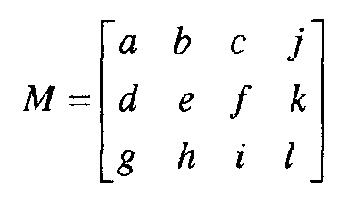
- Projector chromaticity data, M represents various aspects of color and luminance of the projector. As explained below, although this data may represent certain luminance aspects of the projector as well as its color, it is referred to herein as "chromaticity" data to distinguish it from other types of luminance data.
- Relative luminance data, E represents the relative luminance of each color of the color wheel relative to a base rate at which the color wheel is running.
- Overall luminance data, L represents characteristics of its illumination source. As explained below, this data is provided to main controller 13, which returns color correction data to each projector 11.
- CM represents the correction needed for that projector 11 to match its color to a standard color gamut.
- Each projector 11 then uses its color correction data to match its pixel data to that of the standard.
- Main controller 13 performs various control functions required for generating the display, including calculation of the color correction data for each projector 11.
- a bus 14 carries data between projectors 11 and main controller 13.
- FIGURE 2 illustrates a typical data flow of the image data within a projector 11.
- the input data is YCrCb data, such as that provided by a television signal.
- Each projector 11 receives the data appropriate for its tile of the total image.
- the projection display system has some sort of receiver or data storage device for providing the input data.
- a first color space conversion (CSC1) process 21 converts the YCrCb color space to an RGB (red, green, blue) color space.
- a degamma process 22 removes the gamma from the signal, such that the RGB signal is in linear space.
- the input data might already be RGB data, with no need for process 21.
- An RGBY gain process 23 applies gain to the signal.
- Process 23 is essentially for white processing, for projectors 11 whose color wheels have one or more white segments.
- a second color space conversion process (CSC2) process 24 converts the gained RGB signal to a color-corrected space in accordance with the invention.
- process 24 results in pixel data that is color matched between projectors 11. Further details of process 24 are described below.
- Process 24 may also include luminance matching, which compensates for variances in the illumination systems of the projectors.
- Process 25 applies error diffusion and RGBY offset. Error diffusion provides the correct number of bits per pixel for the display.
- the RGBY offset is an additional part of the white processing initiated in process 23.
- the resulting RGBW data is the input data for the projector's SLM.
- FIGURE 3A illustrates the internal components of each projector 11, where projector 11 uses a color wheel.
- each projector 11 is a digital micromirror device (DMDTM) projector.
- DMDTM digital micromirror device
- Each projector 11 has a single DMD 31, which is a type of SLM.
- the DMD 31 has an array of tiny mirrors, each of which are individually addressable with image data. Each mirror can be tilted to either an on or an off position.
- An image is generated by illuminating the DMD 31 with light from a white light source 32, switching the appropriate mirrors on or off and by modulating the time that the on mirrors are on. Images can be generated in such fast sequence, that the viewer perceives motion.
- Each projector 11 has a color wheel 33 for adding color to the images.
- the color wheel 33 has red, green, blue, and white (RGBW) filter segments and spins in sequence with the images' corresponding RGBW data.
- RGBW red, green, blue, and white
- the projector 11 further comprises the color wheel motor 33a, pixel processing unit 34, various optics 35 and 36 for shaping the illumination to the DMD, and a projection lens 37.
- Processing unit 34 has one or more processors and associated memory appropriate for performing the processes of FIGURE 2.
- FIGURE 3B illustrates the internal components of projector 11, where projector 11 uses three SLMs (here DMDs 31) to generate color images. Each DMD 31 generates images of a different color. Optics 39, including a TIR (total internal reflection prism), are used to combine the images into projection lens 37.
- SLMs single-mode laser diode
- TIR total internal reflection prism
- each projector 11 delivers its stored color and luminance data (its chromaticity data, M, its relative luminance data, E, and its luminance data, L) to main controller 13.
- main controller 32 calculates color space correction data, CM, which it delivers to the processing unit 34 of that projector. The projector 11 uses this data during the color and luminance matching process 24.
- controller 13 could communicate with customer interfaces and provide inputs for adjustment of the white point of the system. Or, it could provide outputs of the lamp status of each projector 11, using the luminance data collected from each projector. This could give the customer advanced warning to the need to replace lamp 32 prior to lamp failure.
- Main controller 13 could be a DSP, a microcontroller, or an external computer such as a PC, or workstation. It could be placed within a bus structure 14, which could communicate with each projector 11, polling for the needed color and luminance data and then returning the color correction data. Alternatively, one of the projectors 11 could have a master processing system that performs the role of main controller 13.
- FIGURE 4 illustrates how the color correction data, CM, is calculated and used.
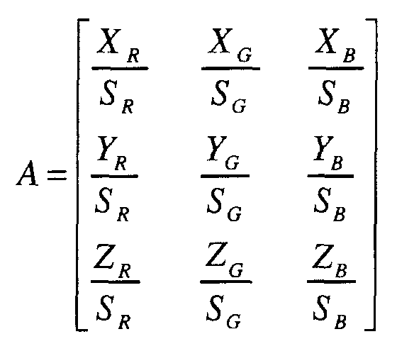
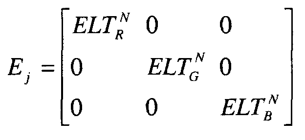
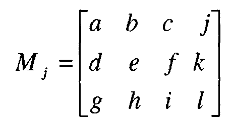
- the chromaticity data and the relative luminance data are calculated in matrix form, designated as the matrices M and E, respectively.
- the color correction data is returned to the projectors in matrix form, designated as CM j , for each projector 11.
- Steps 41 - 43 are performed for each projector 11, resulting in the stored M and E data for each projector 11.
- Steps 44 - 47 are performed by main controller 13, using the M and E data to calculate CM j for each projector 11.
- Step 48 is the actual correction of the RGBW data at each projector 11, using the CM j data from the main controller 13.
- Step 41 involves measuring chromaticity and relative luminances for each projector 11.
- the following chromaticity measurements are obtained, using conventional measurement equipment for measuring chromaticity (X, Y, Z) values off the screen: X R ,Y R ,Z R X G ,Y G ,Z G X B , Y B , Z B X WS , Y WS , Z WS , where the subscript WS indicates white.
- Luminance measurements are also acquired as follows: Y ' / RGB Y ' / WS
- X RGB X R + X G + X B
- Y RGB Y R + Y G + Y B
- RGB Z R + Z G + Z B
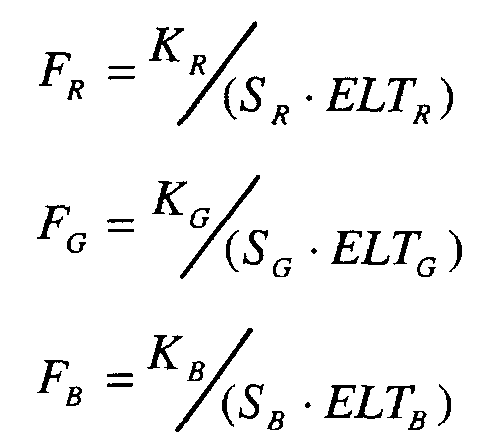
- the relative luminance data, E is based on effective light times (ELTs) of color wheel 33 at a defined standard rate, such as 60 cycles per second.
- ELTs effective light times
- discrepancies between the ELTs at various rates may be insignificant and the measurements and calculations involving the E data could be omitted.
- the relative luminances could be measured for the images generated by the different SLMs.
- ELT's from a standard rate of color wheel 33 are expressed as: ELT S / R, ELT S / G , ELT S / B , ELT S / WS
- X N ⁇ X ⁇ ⁇ ELT ⁇ N ELT ⁇ S
- Y N ⁇ Y ⁇ ⁇ ELT ⁇ N ELT ⁇ S
- Z N ⁇ Z ⁇ ⁇ ELT ⁇ N ELT ⁇ S
- ⁇ R,G,B,WS
- ELT ⁇ S is the standard wheel rate ELT for a given color ⁇
- ELT ⁇ N is the ELT for wheel rate N for a given color ⁇
- X N ⁇ , Y N ⁇ , Z N ⁇ are the new adjusted measurement for the given wheel rate N.
- the above measurements may also be used for various calibration adjustments for the projector 11.
- Step 42 the above measurements are used to calculate a chromaticity matrix, M, and a relative luminance matrix, E, for each projector 11.
- the chromaticity and luminance data is used to calculate two parameters, ⁇ and ⁇ , and to compute white segment colorimetry.
- a relative luminance matrix, E can be derived for each projector 11 from its ELT data as follows: , where N is a given color wheel rate.
- Step 43 the color and luminance data for each projector 11 is stored in memory of its processing unit 34.
- This data includes the above-described matrices M and E, which are to be subsequently downloaded to main controller 13. Alternatively, data used to derive these matrices may be stored, then downloaded to main controller 13, which calculates the matrices.
- the color wheel 33 has an associated EPROM, where this data may be stored.
- Each projector 11 now has its own colorimetry stored in its memory.
- Step 44 is to compute a standard color gamut, which will be used as the standard to which all projectors 11 are matched. This can be accomplished by finding the largest color gamut triangle that is contained within the color gamut of all the projectors 11. This color gamut can be found by pairing two projectors, and finding the largest color gamut which is contained within their color gamut. This new color gamut is then paired with all other projectors, and a new gamut established from each pairing.
- FIGURE 5 illustrates the process of determining the standard color gamut. As shown, the standard gamut is the largest color gamut completely contained within four projector gamuts.
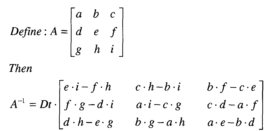
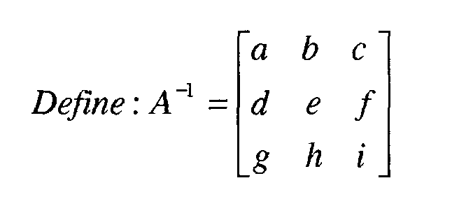
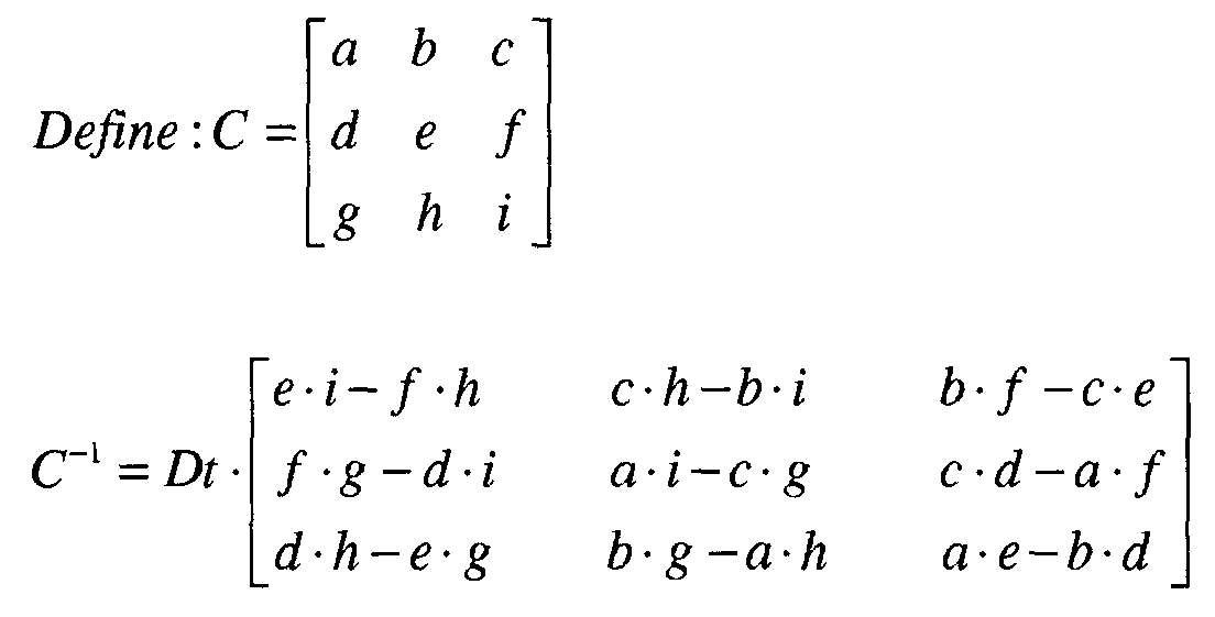
- the standard color gamut is used to determine a standard color matrix, M T .
- Known techniques may be used to calculate the matrix from the gamut. These techniques generally involve selecting three points from the standard gamut and a white point.
- the white point can be defined as either the average white point of all projectors 11 or as an arbitrary white point.
- Step 46 is calculating a color correction matrix, CM j , for each projector 11.
- CM j a color correction matrix
- CM color correction data
- E T is a standard relative luminance matrix derived from the standard wheel rates described above in connection with Step 41.
- the luminance level of each projector 11 is matched. This can be accomplished using either a direct measurement of each projector 11, or through use of a sensor internal to each projector 11.
- This internal sensor could be a sensor placed in a dump light path or other suitable location in which the light is proportional to the lamp output. This sensor could be calibrated in the factory to read a number related to the luminance level of the projector 11.
- the luminance data, L, of each projector 11 can be used to adjust the gain levels of the CM matrix.
- color correction for screen colorimetric performance could be performed. This could include correction for reduced blue saturation, or general white point movement due to the screen.
- the color correction matrix, CM for each projector 11 can now be downloaded into that projector 11.
- Each projector 11 uses this matrix to perform the color matching process 24 of FIGURE 2.
- its images are color corrected into the gamut defined by C T ⁇ E T .
- the relative luminance data could be incorporated into the C matrix.
- the above is but one example of a color correction matrix.
- U.S. Patent Serial No. 09/561,160 entitled “Enhanced Color Correction", and incorporated by reference herein, describes an alternative color correction matrix.
- the color correction matrix is a 3 x 3 matrix, but is derived from a 3x7 matrix that includes secondary color values as well as primary color values.
- Using the enhanced color correction technique provides additional flexibility in the color correction of multiple display systems. This includes larger color gamuts and brighter displays.
- DMD digital micromirror device
Landscapes
- Engineering & Computer Science (AREA)
- Multimedia (AREA)
- Signal Processing (AREA)
- Video Image Reproduction Devices For Color Tv Systems (AREA)
- Controls And Circuits For Display Device (AREA)
- Control Of Indicators Other Than Cathode Ray Tubes (AREA)
- Projection Apparatus (AREA)
Abstract
Description
XR,YR,ZR
XG,YG,ZG
XB, YB, ZB
XWS, YWS, ZWS
, where the subscript WS indicates white. Luminance measurements are also acquired as follows:
Y ' / RGB
Y ' / WS
The following chromaticity terms are defined:
ELT S / R, ELT S / G, ELT S / B, ELT S / WS


Claims (23)
- A method of color matching images generated by multiple projectors of a tiled projection display system, each projector having a processing unit and the system having a main controller, comprising the steps of:storing chromaticity data in the processing unit of each projector, representing at least the colors of images generated by that projector;communicating each projector's chromaticity data to the main controller;storing standard color gamut data at the main controller, representing a standard color gamut to which the projectors are to be matched;calculating, at the main controller, color correction data for each projector, based on that projector's chromaticity data and on the standard color gamut data;communicating each projector's color correction data from the main controller to that projector; andcalculating pixel values, using the processing system of each projector, on the basis of that projector's color correction data.
- The method of Claim 1, wherein the chromaticity data further represents luminance of images generated by the projector.
- The method of Claim 1, further comprising the steps of:storing projector relative luminance data in the processing unit of each projector, representing the relative luminance of colors generated by that projector; and of storing standard relative luminance data at the main controller, representing a standard relative luminance of colors to which the projectors are to be matched; and wherein the communicating step is performed by also communicating this projector relative luminance data; and the calculating step is performed such that the color correction data is further based on the projector relative luminance data.
- The method of Claim 3, wherein the projectors each use a color wheel, and wherein relative luminance data represents effective light times of each color.
- The method of Claim 1, further comprising the step of storing additional data representing the luminance of a light source of each projector, and wherein the communicating step is performed by also communicating this luminance data, and further comprising the step of adjusting the gain of the color correction data based on the luminance data.
- The method of Claim 1, wherein the step of communicating each projector's chromaticity data is performed by communicating the data in the form of a transfer function matrix.
- The method of Claim 1, wherein the chromaticity data is calculated from primary and white color values.
- The method of Claim 1, wherein the main controller is a processing system in data communication with each projector.
- The method of Claim 1, wherein the main controller is also one of the projector processing units.
- The method of Claim 1, wherein each projector generates images using a spatial light modulator.
- The method of Claim 1, wherein the color correction data is derived from primary and secondary colors.
- A projector for a tiled projection display system, the display system having a main controller, comprising:a set of projectors, each projector operable to generate a portion of an image, and each projector having a light path along at least the following elements: a light source, a color wheel, a spatial light modulator, and a projection lens, each projector further having a processing unit for processing pixel values for image data to be delivered to the spatial light modulator; andwherein each processing unit stores chromaticity data associated with that processor; andwherein each processor is operable to deliver the chromaticity data to the main controller, to receive color correction data from the main controller, and to calculate pixel values based on the color correction data.
- The projector of Claim 12, wherein the spatial light modulator is a digital micro mirror device.
- The projector of Claim 12, wherein the chromaticity data represents both color and luminance of images generated by the spatial light modulator.
- The projector of Claim 12, wherein the processing unit further stores and delivers relative luminance data representing relative luminance of colors generated by the projector.
- The projector of Claim 15, wherein the relative luminance data represents effective light times of the color wheel.
- The projector of Claim 12, wherein the processing unit further stores and delivers luminance data representing luminance characteristics of the light source.
- The projector of Claim 12, wherein the color correction data is derived from primary and secondary colors.
- A projector for a tiled projection display system, the display system having a main controller, comprising:a set of projectors, each projector operable to generate a portion of an image, and each projector having a light path along at least the following elements: a light source, two or more spatial light modulators, and a projection lens, each projector further having a processing unit for processing pixel values for image data to be delivered to the spatial light modulator; andwherein each processing unit stores chromaticity data associated with that processor; andwherein each processor is operable to deliver the chromaticity data to the main controller, to receive color correction data from the main controller, and to calculate pixel values based on the color correction data.
- The projector of Claim 19, wherein the spatial light modulator is a digital micro mirror device.
- The projector of Claim 19, wherein the chromaticity data represents both color and luminance of images generated by the spatial light modulator.
- The projector of Claim 19, wherein the processing unit further stores and delivers luminance data representing luminance characteristics of the light source.
- The projector of Claim 19, wherein the color correction data is derived from primary and secondary colors.
Applications Claiming Priority (2)
| Application Number | Priority Date | Filing Date | Title |
|---|---|---|---|
| US22962500P | 2000-08-31 | 2000-08-31 | |
| US229625 | 2000-08-31 |
Publications (3)
| Publication Number | Publication Date |
|---|---|
| EP1185110A2 true EP1185110A2 (en) | 2002-03-06 |
| EP1185110A3 EP1185110A3 (en) | 2005-11-02 |
| EP1185110B1 EP1185110B1 (en) | 2010-02-10 |
Family
ID=22862030
Family Applications (1)
| Application Number | Title | Priority Date | Filing Date |
|---|---|---|---|
| EP01000413A Expired - Lifetime EP1185110B1 (en) | 2000-08-31 | 2001-08-30 | Automated color matching for tiled projection system |
Country Status (3)
| Country | Link |
|---|---|
| US (1) | US7515746B2 (en) |
| EP (1) | EP1185110B1 (en) |
| DE (1) | DE60141262D1 (en) |
Families Citing this family (23)
| Publication number | Priority date | Publication date | Assignee | Title |
|---|---|---|---|---|
| US7283181B2 (en) | 2002-01-31 | 2007-10-16 | Hewlett-Packard Development Company, L.P. | Selectable color adjustment for image display |
| US7391475B2 (en) * | 2002-01-31 | 2008-06-24 | Hewlett-Packard Development Company, L.P. | Display image generation with differential illumination |
| US7460179B2 (en) * | 2002-01-31 | 2008-12-02 | Hewlett-Packard Development Company, L.P. | Adaptive image display |
| US7154458B2 (en) * | 2002-08-21 | 2006-12-26 | Nec Viewtechnology, Ltd. | Video display device with spatial light modulator |
| US20060007406A1 (en) * | 2002-10-21 | 2006-01-12 | Sean Adkins | Equipment, systems and methods for control of color in projection displays |
| US7074418B2 (en) * | 2002-11-18 | 2006-07-11 | Changaris David G | Conjugated fatty acid based emulsion and methods for preparing and using same |
| US7184054B2 (en) * | 2003-01-21 | 2007-02-27 | Hewlett-Packard Development Company, L.P. | Correction of a projected image based on a reflected image |
| US8567953B2 (en) * | 2005-04-26 | 2013-10-29 | Imax Corporation | Systems and methods for projecting composite images |
| KR20070014862A (en) * | 2005-07-29 | 2007-02-01 | 삼성전자주식회사 | Image signal processing device, liquid crystal display device and driving method thereof |
| US8976080B2 (en) * | 2005-12-06 | 2015-03-10 | Dolby Laboratories Licensing Corporation | Multi-segment imager |
| CN101416227B (en) * | 2005-12-06 | 2011-02-23 | 杜比实验室特许公司 | Modular Electronic Display |
| EP2122395A1 (en) | 2006-12-18 | 2009-11-25 | Thomson Licensing | 2d/3d projector with rotating translucent cylinder for alternating light polarisation |
| US20100014008A1 (en) * | 2006-12-19 | 2010-01-21 | Youngshik Yoon | Wide color gaut high resolution dmd projection system |
| WO2008076114A1 (en) * | 2006-12-19 | 2008-06-26 | Thomson Licensing | High resolution dmd projection system |
| US8363267B2 (en) * | 2007-06-01 | 2013-01-29 | Samsung Electronics Co., Ltd. | Image forming apparatus and color converting method thereof |
| EP2160647A1 (en) * | 2007-06-25 | 2010-03-10 | Thomson Licensing | Video recording prevention system |
| US20120128246A1 (en) * | 2008-06-27 | 2012-05-24 | High Definition Integration, LTD | Methods and systems for color management in display systems |
| US9052584B2 (en) * | 2009-04-28 | 2015-06-09 | The Regents Of The University Of California | Color seamlessness across tiled multi-projector displays |
| US8310499B2 (en) * | 2009-09-10 | 2012-11-13 | Seiko Epson Corporation | Balancing luminance disparity in a display by multiple projectors |
| US8267531B2 (en) * | 2010-03-26 | 2012-09-18 | Seiko Epson Corporation | Correcting row and column shifts in a calibration matrix for a projection system |
| US8342696B2 (en) * | 2010-03-26 | 2013-01-01 | Seiko Epson Corporation | System and method for displaying remote content through multiple projectors |
| KR20120088103A (en) * | 2011-01-31 | 2012-08-08 | 삼성전자주식회사 | Image processing device |
| CN104599636B (en) * | 2015-02-10 | 2017-03-01 | 西安诺瓦电子科技有限公司 | LED display bright chroma bearing calibration and bright chroma correction coefficient generating means |
Family Cites Families (24)
| Publication number | Priority date | Publication date | Assignee | Title |
|---|---|---|---|---|
| JP2706269B2 (en) * | 1988-02-29 | 1998-01-28 | 株式会社リコー | Color image forming method |
| US5079544A (en) * | 1989-02-27 | 1992-01-07 | Texas Instruments Incorporated | Standard independent digitized video system |
| EP0447228A3 (en) * | 1990-03-16 | 1993-01-07 | Hewlett-Packard Company | Data stream concentrator providing attribute data storage and graphics pipeline access |
| US5253043A (en) * | 1991-10-24 | 1993-10-12 | Da Vinci Systems, Inc. | Upsampled interpolative processing of digital video signals |
| JP3116472B2 (en) * | 1991-11-18 | 2000-12-11 | ソニー株式会社 | White balance adjustment method |
| US5512961A (en) * | 1993-03-24 | 1996-04-30 | Apple Computer, Inc. | Method and system of achieving accurate white point setting of a CRT display |
| EP0650291B1 (en) * | 1993-09-29 | 2002-04-24 | Canon Kabushiki Kaisha | Image processing apparatus and image processing method |
| US5412186A (en) * | 1994-02-23 | 1995-05-02 | Texas Instruments Incorporated | Elimination of sticking of micro-mechanical devices |
| US5612753A (en) * | 1995-01-27 | 1997-03-18 | Texas Instruments Incorporated | Full-color projection display system using two light modulators |
| US5986721A (en) * | 1995-06-13 | 1999-11-16 | Texas Instruments Incorporated | Producing a rendered image version of an original image using an image structure map representation of the image |
| JPH09146496A (en) * | 1995-11-17 | 1997-06-06 | Nec Corp | Projector with color and brightness unevenness correction circuit |
| CA2222031C (en) * | 1996-03-25 | 2002-01-29 | Rainbow Displays, Inc. | Tiled, flat-panel displays with color-correction capability |
| JP3907783B2 (en) * | 1996-12-12 | 2007-04-18 | 富士フイルム株式会社 | Color conversion method |
| US6054832A (en) * | 1997-05-30 | 2000-04-25 | Texas Instruments Incorporated | Electronically programmable color wheel |
| US6453067B1 (en) * | 1997-10-20 | 2002-09-17 | Texas Instruments Incorporated | Brightness gain using white segment with hue and gain correction |
| JP3714163B2 (en) * | 1997-12-12 | 2005-11-09 | 株式会社日立製作所 | Video display system |
| US6505252B1 (en) * | 1997-12-24 | 2003-01-07 | Seiko Epson Corporation | Data transfer utilizing preview data |
| US5921650A (en) * | 1998-02-27 | 1999-07-13 | International Business Machines Corporation | High efficiency field-sequential color projector using two SLMs |
| JP3514776B2 (en) * | 1998-04-15 | 2004-03-31 | 三菱電機株式会社 | Multi vision system |
| JPH11305970A (en) * | 1998-04-27 | 1999-11-05 | Canon Inc | Image processing apparatus, method, and recording medium |
| JPH11341296A (en) * | 1998-05-28 | 1999-12-10 | Sony Corp | Color gamut conversion method and color gamut conversion device |
| JP2000115558A (en) * | 1998-10-08 | 2000-04-21 | Mitsubishi Electric Corp | Color characteristic description device, color management device, image conversion device, and color correction method |
| US6559826B1 (en) * | 1998-11-06 | 2003-05-06 | Silicon Graphics, Inc. | Method for modeling and updating a colorimetric reference profile for a flat panel display |
| EP1063852A2 (en) * | 1999-06-21 | 2000-12-27 | Sony Corporation | Image projector |
-
2001
- 2001-08-30 DE DE60141262T patent/DE60141262D1/en not_active Expired - Lifetime
- 2001-08-30 EP EP01000413A patent/EP1185110B1/en not_active Expired - Lifetime
- 2001-08-31 US US09/945,295 patent/US7515746B2/en not_active Expired - Lifetime
Also Published As
| Publication number | Publication date |
|---|---|
| EP1185110A3 (en) | 2005-11-02 |
| DE60141262D1 (en) | 2010-03-25 |
| US7515746B2 (en) | 2009-04-07 |
| EP1185110B1 (en) | 2010-02-10 |
| US20020041708A1 (en) | 2002-04-11 |
Similar Documents
| Publication | Publication Date | Title |
|---|---|---|
| US7515746B2 (en) | Automated color matching for tiled projection system | |
| CN110958438B (en) | Device and method for photometric compensation of an image provided by a display device | |
| US8570363B2 (en) | Display of generalized anaglyphs without retinal rivalry | |
| EP1104923B1 (en) | Colour sequential light valve display device | |
| US8177367B2 (en) | 2D/3D switchable color display apparatus with narrow band emitters | |
| KR102936507B1 (en) | Color uniformity correction of display devices | |
| JP2001209358A (en) | Unevenness correction of display image | |
| EP2519013B1 (en) | Projection apparatus, projection method, and storage medium having program stored thereon | |
| EP3253053B1 (en) | Projection image correcting method and projection apparatus | |
| EP1061500A2 (en) | Color correction in image display | |
| US9635327B2 (en) | Projector, color correction device, and projection method | |
| JP2015525037A (en) | Method for reducing metamerism mismatch between observers | |
| US7070286B2 (en) | Projector with projection lens having a zoom function | |
| US6975337B2 (en) | Projection type image display device | |
| US9022576B2 (en) | Image correction apparatus, method and medium | |
| US6771233B1 (en) | Projection display device using two liquid crystal display panels | |
| JP2003125317A (en) | Video projection system, video projection method, video signal processing device, video signal processing method, video projection device, and video projection method | |
| Kresse et al. | Color consistency for digital multi-projector stereo display systems: the heyewall and the digital cave | |
| US20050185143A1 (en) | Optical arrangement for non-inverting illumination system | |
| JP2009237240A (en) | Image adjusting device, image display system, and image adjusting method | |
| CN114842779B (en) | Laser projection image display method, apparatus and computer storage medium | |
| KR100350987B1 (en) | Display device and display method using single liquid crystal display panel | |
| JP2009098627A (en) | Projection video display device | |
| Tominaga et al. | A color control method for image output with projection displays | |
| JP2009168886A (en) | Image correction apparatus, image display system, and image correction method |
Legal Events
| Date | Code | Title | Description |
|---|---|---|---|
| PUAI | Public reference made under article 153(3) epc to a published international application that has entered the european phase |
Free format text: ORIGINAL CODE: 0009012 |
|
| AK | Designated contracting states |
Kind code of ref document: A2 Designated state(s): AT BE CH CY DE DK ES FI FR GB GR IE IT LI LU MC NL PT SE TR |
|
| AX | Request for extension of the european patent |
Free format text: AL;LT;LV;MK;RO;SI |
|
| PUAL | Search report despatched |
Free format text: ORIGINAL CODE: 0009013 |
|
| AK | Designated contracting states |
Kind code of ref document: A3 Designated state(s): AT BE CH CY DE DK ES FI FR GB GR IE IT LI LU MC NL PT SE TR |
|
| AX | Request for extension of the european patent |
Extension state: AL LT LV MK RO SI |
|
| RIC1 | Information provided on ipc code assigned before grant |
Ipc: 7H 04N 9/31 B Ipc: 7H 04N 9/12 A |
|
| 17P | Request for examination filed |
Effective date: 20060502 |
|
| AKX | Designation fees paid |
Designated state(s): DE FR GB |
|
| 17Q | First examination report despatched |
Effective date: 20060704 |
|
| RIC1 | Information provided on ipc code assigned before grant |
Ipc: H04N 9/31 20060101AFI20090728BHEP Ipc: H04N 9/73 20060101ALN20090728BHEP |
|
| GRAP | Despatch of communication of intention to grant a patent |
Free format text: ORIGINAL CODE: EPIDOSNIGR1 |
|
| GRAS | Grant fee paid |
Free format text: ORIGINAL CODE: EPIDOSNIGR3 |
|
| GRAA | (expected) grant |
Free format text: ORIGINAL CODE: 0009210 |
|
| AK | Designated contracting states |
Kind code of ref document: B1 Designated state(s): DE FR GB |
|
| REG | Reference to a national code |
Ref country code: GB Ref legal event code: FG4D |
|
| REF | Corresponds to: |
Ref document number: 60141262 Country of ref document: DE Date of ref document: 20100325 Kind code of ref document: P |
|
| PLBE | No opposition filed within time limit |
Free format text: ORIGINAL CODE: 0009261 |
|
| STAA | Information on the status of an ep patent application or granted ep patent |
Free format text: STATUS: NO OPPOSITION FILED WITHIN TIME LIMIT |
|
| 26N | No opposition filed |
Effective date: 20101111 |
|
| REG | Reference to a national code |
Ref country code: FR Ref legal event code: PLFP Year of fee payment: 16 |
|
| PGFP | Annual fee paid to national office [announced via postgrant information from national office to epo] |
Ref country code: DE Payment date: 20160831 Year of fee payment: 16 Ref country code: GB Payment date: 20160725 Year of fee payment: 16 |
|
| PGFP | Annual fee paid to national office [announced via postgrant information from national office to epo] |
Ref country code: FR Payment date: 20160719 Year of fee payment: 16 |
|
| REG | Reference to a national code |
Ref country code: DE Ref legal event code: R119 Ref document number: 60141262 Country of ref document: DE |
|
| GBPC | Gb: european patent ceased through non-payment of renewal fee |
Effective date: 20170830 |
|
| REG | Reference to a national code |
Ref country code: FR Ref legal event code: ST Effective date: 20180430 |
|
| PG25 | Lapsed in a contracting state [announced via postgrant information from national office to epo] |
Ref country code: DE Free format text: LAPSE BECAUSE OF NON-PAYMENT OF DUE FEES Effective date: 20180301 Ref country code: GB Free format text: LAPSE BECAUSE OF NON-PAYMENT OF DUE FEES Effective date: 20170830 |
|
| PG25 | Lapsed in a contracting state [announced via postgrant information from national office to epo] |
Ref country code: FR Free format text: LAPSE BECAUSE OF NON-PAYMENT OF DUE FEES Effective date: 20170831 |