EP1185060A2 - State monitoring method and apparatus in subscriber line test - Google Patents
State monitoring method and apparatus in subscriber line test Download PDFInfo
- Publication number
- EP1185060A2 EP1185060A2 EP01120629A EP01120629A EP1185060A2 EP 1185060 A2 EP1185060 A2 EP 1185060A2 EP 01120629 A EP01120629 A EP 01120629A EP 01120629 A EP01120629 A EP 01120629A EP 1185060 A2 EP1185060 A2 EP 1185060A2
- Authority
- EP
- European Patent Office
- Prior art keywords
- line
- line test
- test instruction
- control terminal
- subscriber
- Prior art date
- Legal status (The legal status is an assumption and is not a legal conclusion. Google has not performed a legal analysis and makes no representation as to the accuracy of the status listed.)
- Granted
Links
Images



Classifications
-
- H—ELECTRICITY
- H04—ELECTRIC COMMUNICATION TECHNIQUE
- H04M—TELEPHONIC COMMUNICATION
- H04M3/00—Automatic or semi-automatic exchanges
- H04M3/22—Arrangements for supervision, monitoring or testing
- H04M3/26—Arrangements for supervision, monitoring or testing with means for applying test signals or for measuring
- H04M3/28—Automatic routine testing ; Fault testing; Installation testing; Test methods, test equipment or test arrangements therefor
- H04M3/30—Automatic routine testing ; Fault testing; Installation testing; Test methods, test equipment or test arrangements therefor for subscriber's lines, for the local loop
Definitions
- the present invention relates to a state monitoring method and apparatus in a subscriber line test between a telephone exchange and an ADSL (Asymmetric Digital Subscriber Line) apparatus.
- ADSL Asymmetric Digital Subscriber Line
- POTS Personal Telephone Service
- ADSL Advanced Subscriber Line
- a subscriber who is receiving a POTS which is an existing telephone service through a telephone exchange
- an ADSL service which is asymmetric digital subscriber line communication. Since POTS control in a telephone exchange and ADSL control in an ADSL apparatus are mutually independent, it is impossible for the telephone exchange to know the state of the ADSL apparatus, and vice versa. For this reason, a line blocked state due to a line test instruction from one control terminal looks like a fault to the other control terminal.
- Fig. 4 shows a conventional communication system.
- the conventional communication system shown in Fig. 4 is comprised of a subscriber 3 constituted by a telephone 31 and terminal 32, a multiplexing/matching circuit 8 to which the telephone 31 and terminal 32 are connected and which executes line matching and modulates/multiplexes a voice signal from the telephone 31 and a data signal from the terminal 32 in different frequency bands, a demultiplexing circuit 9 for demultiplexing the multiplexed voice signal and data signal, a telephone exchange 1 for receiving the voice signal from the demultiplexing circuit 9, an ADSL control section 21 for receiving the data signal from the demultiplexing circuit 9, a control terminal 4 which is connected to the telephone exchange 1 to maintain and manage the telephone exchange 1, a data network 7 to which an ADSL apparatus 2 -is connected, a control terminal 5 which is connected to the data network 7 to maintain and manage various units subordinate to the data network 7, and a PSTN 6 to which the telephone exchange 1 is connected.
- the telephone exchange 1 includes a POTS control section 11 which is a subscriber circuit of the telephone exchange 1 and sends a telephone voice signal to a PSTN (Public Switched Telephone Network) upon converting it into a digital signal, and a host apparatus 12 for controlling transmission/reception of the voice data as the digital signal.
- the ADSL apparatus 2 includes the ADSL control section 21, which is a subscriber circuit of the ADSL apparatus 2, and a host apparatus 22 for controlling transmission/reception of data signals to/from the terminal 32.
- the control terminal 5 on the ADSL apparatus 2 side knows nothing about a line test instruction from the control terminal 4 on the telephone exchange 1 side. For this reason, the control terminal 5 determines even a line blocked state for a line test as a line blocked state of the subscriber 3, i.e., a fault.
- a state monitoring method in a subscriber line test in a communication system in which a subscriber telephone and a subscriber terminal are independently connected to a telephone exchange and an ADSL (Asymmetric Digital Subscriber Line) apparatus through a subscriber line comprising the steps of connecting, through an interface, the telephone exchange to which a first control terminal is connected to the ADSL apparatus to which a second control terminal is connected, notifying a line blocked state due to a line test instruction from one of the first and second control terminals to the other of the first and second control terminals through the interface, and causing the other of the first and second control terminals to determine, when receiving a notification of the line block state due to the line test instruction, that the line blocked state is not caused by a fault.
- ADSL Asymmetric Digital Subscriber Line
- Fig. 1 shows a communication system according to an embodiment of the present invention.
- the communication system shown in Fig. 1 is comprised of a subscriber 103 constituted by a telephone 131 and terminal 132, a multiplexing/matching circuit 108 to which the telephone 131 and terminal 132 are connected and which executes line matching and modulates/multiplexes a voice signal from the telephone 131 and a data signal from the terminal 132 in different frequency bands, a demultiplexing circuit 109 for demultiplexing the multiplexed voice signal and data signal, a telephone exchange 101 for receiving the voice signal from the demultiplexing circuit 109, an ADSL apparatus 102 for receiving the data signal from the demultiplexing circuit 109, a control terminal 104 which is connected to the telephone exchange 101 to maintain and manage the telephone exchange 101, a data network 107 to which the ADSL apparatus 102 is connected, a control terminal 105 which is connected to the data network 107 to maintain and manage various units subordinate to the data network 107, and a PSTN
- a host apparatus 112 of the telephone exchange 101 is connected to a host apparatus 122 of the ADSL apparatus 102 through an interface 110.
- the control terminals 104 and 105 respectively have determining sections 104a and 105a each for determining the blocked state of a subscriber line.
- the telephone exchange 101 includes a POTS control section 111 which is a subscriber circuit of the telephone exchange 101 and sends a telephone voice signal to a PSTN (Public Switched Telephone Network) upon converting it into a digital signal, and a host apparatus 112 for controlling transmission/reception of the voice data as the digital signal.
- the host apparatus 112 includes a determining section 112a for determining a block instruction, a blocking section 112b for blocking the subscriber line, and a transmitting section 112c for transmitting line test information to the control terminal 104.
- the ADSL apparatus 102 includes an ADSL control section 121 which is a subscriber circuit of the ADSL apparatus 102, and the host apparatus 122 for controlling transmission/reception of data signals to/from the terminal 132.
- the host apparatus 122 includes a determining section 122a for determining a block instruction, a blocking section 122b for blocking the subscriber line, and a transmitting section 122c for transmitting line test information to the control terminal 105.
- a voice signal from the telephone 131 of the subscriber 103 and a data signal from the terminal 132 are multiplexed by the multiplexing/matching circuit 108.
- the multiplexed signal is transmitted to the multiplexing/matching circuit 108 by using different frequency bands on the same wire.
- the voice signal demultiplexed by the demultiplexing circuit 109 is output to the POTS control section 111, and the data signal to the ADSL control section 121.
- the POTS control section 111 converts the voice signal from the telephone 131 of the subscriber 103 into a digital signal, and transmits it to the PSTN (Public Switched Telephone Network) 106 through the host apparatus 112.
- PSTN Public Switched Telephone Network
- the ADSL control section 121 processes the data signal from the terminal 132 of the subscriber 103 and transmits the resultant signal to the data network 107 through the host apparatus 122.
- the host apparatuses 112 and 122 notify each other of the states of lines under the control of the respective apparatuses through the interface 110
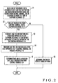
- control terminal 104 on the telephone exchange 101 side outputs a line test instruction and line block instruction to the telephone exchange 101, and the blocking section 112b blocks the line of the subscriber 103 (step S1).
- the determining section 112a then checks whether a line test instruction is output from the control terminal 104 (step S2).
- the telephone exchange 101 drops line test instruction data from the host apparatus 112 of the telephone exchange 101 to the interface 110 to transmit the line test instruction data to the host apparatus 122 on the ADSL apparatus 102 side (step S3).
- the determining section 122a of the host apparatus 122 transmits the line test instruction data, received through the interface 110, to the control terminal 105 (step S4).
- the control terminal 105 can be indirectly notified of the state of a line subordinate to the control terminal 104, although there is actually no direct interface between the control terminal 104 and the control terminal 105.
- the determining section 105a of the control terminal 105 When the determining section 105a of the control terminal 105 receives the line test instruction data, the section 105a recognizes that the subscriber line is in a blocked state due to an instruction from the control terminal 104, thereby determining that the blocked state is not a fault (step S5). If no line test instruction is output from the control terminal 104, the determining section 105a determines that the subscriber line is in a blocked state due to a fault (step S6).
- the control terminal 105 transmits line test instruction information (including line block instruction information) to the ADSL apparatus 102 through the data network 107 (step S11).
- the blocking section 122b blocks the subscriber line.
- the determining section 122a checks whether -line test instruction information is output from the control terminal 105 (step S12).
- the host apparatus 122 of the ADSL apparatus 102 drops the line test instruction information to the interface 110 to transmit it to the host apparatus 112 of the telephone exchange 101 (step S13).
- the transmitting section 112c of the host apparatus 112 notifies the control terminal 104 of the line test instruction information (step S14).
- the determining section 104a of the control terminal 104 When the determining section 104a of the control terminal 104 receives the data of the line test instruction information, the section 104a recognizes that the subscriber line is in a blocked state due to the line test instruction from the control terminal 105, thereby determining that the blocked state is not caused by a fault (step S15). If no line test instruction is output from the control terminal 105, the determining section 104a determines that the subscriber line is in a blocked state due to fault (step S16).
- determining section 112a and blocking section 112b are installed in the host apparatus 112 of the telephone exchange 101, their installation positions are not limited as long as they are installed in the telephone exchange 101.
- determining section 122a and blocking section 122b are installed in the host apparatus 122 of the ADSL apparatus 102, their installation positions are not limited as long as they are installed in the ADSL apparatus 102.
- the present invention can prevent a line blocked state due to a line test instruction from the control terminal on one of the telephone exchange side or the ADSL apparatus side from being mistaken for a blocked state due to a fault by the other control terminal.
Landscapes
- Engineering & Computer Science (AREA)
- Signal Processing (AREA)
- Monitoring And Testing Of Exchanges (AREA)
- Telephonic Communication Services (AREA)
Abstract
Description
Claims (8)
- A state monitoring method in a subscriber line test in a communication system in which a subscriber telephone (131) and a subscriber terminal (132) are independently connected to a telephone exchange and an ADSL (Asymmetric Digital Subscriber Line) apparatus through a subscriber line, characterized by comprising the steps of:connecting, through an interface (110), the telephone exchange to which a first control terminal (104) is connected to the ADSL apparatus to which a second control terminal is connected;notifying a line blocked state due to a line test instruction from one of the first and second control terminals to the other of the first and second control terminals through the interface; andcausing the other of the first and second control terminals to determine, when receiving a notification of the line block state due to the line test instruction, that the line blocked state is not caused by a fault.
- A method according to claim 1, whereinthe step of notifying comprises the steps of:sending out a line test instruction for performing a line test on a subscriber line and a line block instruction from the first control terminal to the telephone exchange, and blocking the subscriber line;when the subscriber is blocked, determining whether a line test instruction is output from the first control terminal; andwhen a line test instruction is output, transmitting line test instruction data from a host apparatus (112) of the telephone exchange to an host apparatus (122) of the ADSL apparatus through the interface, andthe step of determining comprises the steps of:transmitting the line test instruction data received through the interface from the host apparatus of the ADSL apparatus to the second control terminal; andwhen the second control terminal receives line test instruction data, determining that the line blocked state is not caused by a fault.
- A method according to claim 1, whereinthe step of notifying comprises the steps of:sending out a line test instruction for performing a line test on a subscriber line and a line block instruction from the second control terminal to the ADSL apparatus, and blocking the subscriber line;when the subscriber is blocked, determining whether a line test instruction is output from the second control terminal; andwhen a line test instruction is output, transmitting line test instruction data from a host apparatus (122) of the ADSL apparatus to an host apparatus (112) of the telephone exchange through the interface, andthe step of determining comprises the steps of:transmitting the line test instruction data received through the interface from the host apparatus of the telephone exchange to the first control terminal; andwhen the first control terminal receives line test instruction data, determining that the line blocked state is not caused by a fault.
- A state monitoring apparatus in a subscriber line test, characterized by comprising:a telephone exchange (101) and an ADSL (Asymmetric Digital Subscriber Line) apparatus (102) to which a subscriber telephone (131) and a subscriber terminal (132) are independently connected through a common subscriber line;a first control terminal (104) connected to said telephone exchange;a second control terminal (105) connected to said ADSL apparatus through a data network (107); andan interface (110) for notifying a line blocked state due to a line test instruction from one of said first and second control terminals to the other of said first and second control terminals.
- An apparatus according to claim 4, wherein said telephone exchange comprises:said ADSL apparatus comprises transmitting means (122c) for, when a line test instruction is output, receiving line test instruction data from said telephone exchange through said interface, and transmitting the data to said second control terminal, andline blocking means (112b) for blocking the subscriber line on the basis of a line test instruction for a line test on the subscriber line and a line block instruction which are sent out from said first control terminal; anddetermining means (112a) for determining whether a line test instruction is output from said first control terminal,
said second control terminal comprises determining means (105a) for, when line test instruction data is received from said ADSL apparatus, determining that the line blocked state is not caused by a fault. - An apparatus according to claim 5, wherein said ADSL apparatus comprises a host apparatus (122) including said transmitting means.
- An apparatus according to claim 4, wherein said ADSL apparatus comprises:said telephone exchange comprises transmitting means (112c) for, when a line test instruction is output, receiving line test instruction data from said ADSL apparatus through said interface, and transmitting the data to said first control terminal, andline blocking means (122b) for blocking the subscriber line on the basis of a line test instruction for a line test on the subscriber line and a line block instruction which are sent out from said second control means; anddetermining means (122a) for determining whether a line test instruction is output from said second control means,
said first control terminal comprises determining means (104a) for, when line test instruction data is received from said telephone exchange, determining that the line blocked state is not caused by a fault. - An apparatus according to claim 7, wherein said telephone exchange comprises a host apparatus (112) including said transmitting means.
Applications Claiming Priority (2)
| Application Number | Priority Date | Filing Date | Title |
|---|---|---|---|
| JP2000260822 | 2000-08-30 | ||
| JP2000260822A JP3570504B2 (en) | 2000-08-30 | 2000-08-30 | Condition monitoring method and device during subscriber line test |
Publications (3)
| Publication Number | Publication Date |
|---|---|
| EP1185060A2 true EP1185060A2 (en) | 2002-03-06 |
| EP1185060A3 EP1185060A3 (en) | 2003-11-05 |
| EP1185060B1 EP1185060B1 (en) | 2007-06-06 |
Family
ID=18748769
Family Applications (1)
| Application Number | Title | Priority Date | Filing Date |
|---|---|---|---|
| EP01120629A Expired - Lifetime EP1185060B1 (en) | 2000-08-30 | 2001-08-29 | State monitoring method and apparatus in subscriber line test |
Country Status (6)
| Country | Link |
|---|---|
| US (1) | US6519320B2 (en) |
| EP (1) | EP1185060B1 (en) |
| JP (1) | JP3570504B2 (en) |
| CN (1) | CN1170413C (en) |
| CA (1) | CA2356210C (en) |
| DE (1) | DE60128759T2 (en) |
Families Citing this family (8)
| Publication number | Priority date | Publication date | Assignee | Title |
|---|---|---|---|---|
| JP4675524B2 (en) * | 2001-09-21 | 2011-04-27 | 富士通株式会社 | Control device for controlling abnormality repair of terminal device |
| CN100454954C (en) * | 2002-03-30 | 2009-01-21 | 中兴通讯股份有限公司 | A Fast Initialization Method for Asymmetric Digital Subscriber Loop Central Office Equipment |
| CN100442722C (en) * | 2005-03-10 | 2008-12-10 | 华为技术有限公司 | Method and device for diagnosing network faults |
| EP1703763A1 (en) * | 2005-03-18 | 2006-09-20 | Alcatel | Communication interface and testing method therefore |
| CN1870687A (en) * | 2005-05-25 | 2006-11-29 | 华为技术有限公司 | Local termial broadband equipment with self-detection function and method for detecting XDSL port |
| CN100461720C (en) * | 2007-01-17 | 2009-02-11 | 中兴通讯股份有限公司 | Device and method for detecting and processing multi-pair DSL equipment |
| CN101494600B (en) * | 2008-11-21 | 2011-08-31 | 深圳市共进电子有限公司 | Network configuration method and apparatus for mirror-image monitoring message information of ADSL terminal |
| TWI766425B (en) * | 2020-11-05 | 2022-06-01 | 中華電信股份有限公司 | System and method for detecting damage of telecommunication cables |
Family Cites Families (11)
| Publication number | Priority date | Publication date | Assignee | Title |
|---|---|---|---|---|
| US5905781A (en) * | 1996-03-29 | 1999-05-18 | Cisco Technology, Inc. | Communication server apparatus and method |
| US6366644B1 (en) * | 1997-09-15 | 2002-04-02 | Cisco Technology, Inc. | Loop integrity test device and method for digital subscriber line (XDSL) communication |
| US6449362B1 (en) * | 1997-11-17 | 2002-09-10 | Bellsouth Intellectual Property Corporation | Apparatus, systems and methods for isolating ADSL signals from POTS signals |
| US6181775B1 (en) * | 1998-11-25 | 2001-01-30 | Westell Technologies, Inc. | Dual test mode network interface unit for remote testing of transmission line and customer equipment |
| US6212258B1 (en) * | 1998-11-25 | 2001-04-03 | Westell Technologies, Inc. | Device for remotely testing a twisted pair transmission line |
| US6278769B1 (en) * | 1998-11-25 | 2001-08-21 | Westell Technologies, Inc. | Signaling method for invoking a test mode in a network interface unit |
| US6349130B1 (en) * | 1998-12-22 | 2002-02-19 | Lucent Technologies, Inc. | Method to pre-qualify copper loops for ADSL service |
| US6292468B1 (en) * | 1998-12-31 | 2001-09-18 | Qwest Communications International Inc. | Method for qualifying a loop for DSL service |
| US6343114B1 (en) * | 1999-12-30 | 2002-01-29 | Turnstone Systems, Inc. | Remotely addressable maintenance unit |
| US6574309B1 (en) * | 2000-03-01 | 2003-06-03 | Turnstone Systems, Inc. | Remotely actuated splittler bypass system and method |
| US6404347B1 (en) * | 2001-05-04 | 2002-06-11 | Excelsus Technologies, Inc. | Alarm filter circuit |
-
2000
- 2000-08-30 JP JP2000260822A patent/JP3570504B2/en not_active Expired - Lifetime
-
2001
- 2001-08-29 US US09/940,804 patent/US6519320B2/en not_active Expired - Fee Related
- 2001-08-29 DE DE60128759T patent/DE60128759T2/en not_active Expired - Lifetime
- 2001-08-29 EP EP01120629A patent/EP1185060B1/en not_active Expired - Lifetime
- 2001-08-30 CA CA002356210A patent/CA2356210C/en not_active Expired - Fee Related
- 2001-08-30 CN CNB011310073A patent/CN1170413C/en not_active Expired - Fee Related
Also Published As
| Publication number | Publication date |
|---|---|
| JP2002077389A (en) | 2002-03-15 |
| CN1340948A (en) | 2002-03-20 |
| EP1185060A3 (en) | 2003-11-05 |
| US6519320B2 (en) | 2003-02-11 |
| DE60128759D1 (en) | 2007-07-19 |
| CN1170413C (en) | 2004-10-06 |
| US20020025025A1 (en) | 2002-02-28 |
| CA2356210C (en) | 2003-12-23 |
| CA2356210A1 (en) | 2002-02-28 |
| JP3570504B2 (en) | 2004-09-29 |
| EP1185060B1 (en) | 2007-06-06 |
| DE60128759T2 (en) | 2007-10-11 |
Similar Documents
| Publication | Publication Date | Title |
|---|---|---|
| AU692628B2 (en) | Signalling techniques and device for high speed data transmission over voiceband channels | |
| CA2111941C (en) | Emergency local switching | |
| US6996134B1 (en) | System and method for reliably communicating telecommunication information | |
| US6072793A (en) | Electronically controlled main distributing frame | |
| EP1185060B1 (en) | State monitoring method and apparatus in subscriber line test | |
| AU712703B2 (en) | Process and device for transmitting confidential connection establishment and service information between subscriber terminals and one or more digital exchanges | |
| KR20010060863A (en) | Home phoneline networking alliance switch system | |
| JP3123942B2 (en) | Bulk transmission method using dedicated line | |
| JP2775846B2 (en) | Time division multiplexer | |
| USRE38472E1 (en) | Multiplexing system for ISDN circuits | |
| US6952417B1 (en) | System and method for selectively providing data communications in an XDSL communication system | |
| JP3632612B2 (en) | Remote side switch reset method and switch system | |
| US6778489B1 (en) | Subscriber terminating equipment | |
| JP3624851B2 (en) | Remote switching system switching method and switching system | |
| JPH088820A (en) | Point / multipoint transmission system | |
| JPH0818626A (en) | Backup multiplex method | |
| KR100210799B1 (en) | Method for setting inter-office signalling system in the switching system | |
| JPH09261700A (en) | Switches and switching systems | |
| JPH02295329A (en) | Subscriber line housing and exchanging device | |
| JPH06209496A (en) | Call connection communication method | |
| JP2003008739A (en) | Method of testing circuit in adsl system | |
| JPH0865281A (en) | Line switching control / multiplexing device | |
| JPH077543A (en) | Automatic reporting system for fault information | |
| JPH04304058A (en) | Radio repeater | |
| JPS5925542B2 (en) | Remote station fault location identification method |
Legal Events
| Date | Code | Title | Description |
|---|---|---|---|
| PUAI | Public reference made under article 153(3) epc to a published international application that has entered the european phase |
Free format text: ORIGINAL CODE: 0009012 |
|
| AK | Designated contracting states |
Kind code of ref document: A2 Designated state(s): AT BE CH CY DE DK ES FI FR GB GR IE IT LI LU MC NL PT SE TR |
|
| AX | Request for extension of the european patent |
Free format text: AL;LT;LV;MK;RO;SI |
|
| PUAL | Search report despatched |
Free format text: ORIGINAL CODE: 0009013 |
|
| AK | Designated contracting states |
Kind code of ref document: A3 Designated state(s): AT BE CH CY DE DK ES FI FR GB GR IE IT LI LU MC NL PT SE TR |
|
| AX | Request for extension of the european patent |
Extension state: AL LT LV MK RO SI |
|
| 17P | Request for examination filed |
Effective date: 20030925 |
|
| AKX | Designation fees paid |
Designated state(s): DE FR SE |
|
| GRAP | Despatch of communication of intention to grant a patent |
Free format text: ORIGINAL CODE: EPIDOSNIGR1 |
|
| GRAS | Grant fee paid |
Free format text: ORIGINAL CODE: EPIDOSNIGR3 |
|
| RIN1 | Information on inventor provided before grant (corrected) |
Inventor name: YANAGI, KAZUYA |
|
| GRAA | (expected) grant |
Free format text: ORIGINAL CODE: 0009210 |
|
| AK | Designated contracting states |
Kind code of ref document: B1 Designated state(s): DE FR SE |
|
| REG | Reference to a national code |
Ref country code: SE Ref legal event code: TRGR |
|
| REF | Corresponds to: |
Ref document number: 60128759 Country of ref document: DE Date of ref document: 20070719 Kind code of ref document: P |
|
| ET | Fr: translation filed | ||
| PLBE | No opposition filed within time limit |
Free format text: ORIGINAL CODE: 0009261 |
|
| STAA | Information on the status of an ep patent application or granted ep patent |
Free format text: STATUS: NO OPPOSITION FILED WITHIN TIME LIMIT |
|
| 26N | No opposition filed |
Effective date: 20080307 |
|
| PGFP | Annual fee paid to national office [announced via postgrant information from national office to epo] |
Ref country code: FR Payment date: 20090814 Year of fee payment: 9 |
|
| PGFP | Annual fee paid to national office [announced via postgrant information from national office to epo] |
Ref country code: DE Payment date: 20090827 Year of fee payment: 9 Ref country code: SE Payment date: 20090806 Year of fee payment: 9 |
|
| EUG | Se: european patent has lapsed | ||
| REG | Reference to a national code |
Ref country code: FR Ref legal event code: ST Effective date: 20110502 |
|
| REG | Reference to a national code |
Ref country code: DE Ref legal event code: R119 Ref document number: 60128759 Country of ref document: DE Effective date: 20110301 |
|
| PG25 | Lapsed in a contracting state [announced via postgrant information from national office to epo] |
Ref country code: DE Free format text: LAPSE BECAUSE OF NON-PAYMENT OF DUE FEES Effective date: 20110301 Ref country code: FR Free format text: LAPSE BECAUSE OF NON-PAYMENT OF DUE FEES Effective date: 20100831 |
|
| PG25 | Lapsed in a contracting state [announced via postgrant information from national office to epo] |
Ref country code: SE Free format text: LAPSE BECAUSE OF NON-PAYMENT OF DUE FEES Effective date: 20100830 |