EP1184916A2 - Sealed type lead acid battery - Google Patents
Sealed type lead acid battery Download PDFInfo
- Publication number
- EP1184916A2 EP1184916A2 EP01121176A EP01121176A EP1184916A2 EP 1184916 A2 EP1184916 A2 EP 1184916A2 EP 01121176 A EP01121176 A EP 01121176A EP 01121176 A EP01121176 A EP 01121176A EP 1184916 A2 EP1184916 A2 EP 1184916A2
- Authority
- EP
- European Patent Office
- Prior art keywords
- pole
- lead acid
- sealed type
- type lead
- acid battery
- Prior art date
- Legal status (The legal status is an assumption and is not a legal conclusion. Google has not performed a legal analysis and makes no representation as to the accuracy of the status listed.)
- Withdrawn
Links
Images


Classifications
-
- H—ELECTRICITY
- H01—ELECTRIC ELEMENTS
- H01M—PROCESSES OR MEANS, e.g. BATTERIES, FOR THE DIRECT CONVERSION OF CHEMICAL ENERGY INTO ELECTRICAL ENERGY
- H01M10/00—Secondary cells; Manufacture thereof
- H01M10/34—Gastight accumulators
- H01M10/342—Gastight lead accumulators
-
- H—ELECTRICITY
- H01—ELECTRIC ELEMENTS
- H01M—PROCESSES OR MEANS, e.g. BATTERIES, FOR THE DIRECT CONVERSION OF CHEMICAL ENERGY INTO ELECTRICAL ENERGY
- H01M50/00—Constructional details or processes of manufacture of the non-active parts of electrochemical cells other than fuel cells, e.g. hybrid cells
- H01M50/10—Primary casings; Jackets or wrappings
- H01M50/102—Primary casings; Jackets or wrappings characterised by their shape or physical structure
- H01M50/103—Primary casings; Jackets or wrappings characterised by their shape or physical structure prismatic or rectangular
-
- H—ELECTRICITY
- H01—ELECTRIC ELEMENTS
- H01M—PROCESSES OR MEANS, e.g. BATTERIES, FOR THE DIRECT CONVERSION OF CHEMICAL ENERGY INTO ELECTRICAL ENERGY
- H01M50/00—Constructional details or processes of manufacture of the non-active parts of electrochemical cells other than fuel cells, e.g. hybrid cells
- H01M50/10—Primary casings; Jackets or wrappings
- H01M50/172—Arrangements of electric connectors penetrating the casing
- H01M50/174—Arrangements of electric connectors penetrating the casing adapted for the shape of the cells
- H01M50/176—Arrangements of electric connectors penetrating the casing adapted for the shape of the cells for prismatic or rectangular cells
-
- H—ELECTRICITY
- H01—ELECTRIC ELEMENTS
- H01M—PROCESSES OR MEANS, e.g. BATTERIES, FOR THE DIRECT CONVERSION OF CHEMICAL ENERGY INTO ELECTRICAL ENERGY
- H01M50/00—Constructional details or processes of manufacture of the non-active parts of electrochemical cells other than fuel cells, e.g. hybrid cells
- H01M50/10—Primary casings; Jackets or wrappings
- H01M50/183—Sealing members
- H01M50/184—Sealing members characterised by their shape or structure
-
- H—ELECTRICITY
- H01—ELECTRIC ELEMENTS
- H01M—PROCESSES OR MEANS, e.g. BATTERIES, FOR THE DIRECT CONVERSION OF CHEMICAL ENERGY INTO ELECTRICAL ENERGY
- H01M50/00—Constructional details or processes of manufacture of the non-active parts of electrochemical cells other than fuel cells, e.g. hybrid cells
- H01M50/10—Primary casings; Jackets or wrappings
- H01M50/183—Sealing members
- H01M50/186—Sealing members characterised by the disposition of the sealing members
-
- H—ELECTRICITY
- H01—ELECTRIC ELEMENTS
- H01M—PROCESSES OR MEANS, e.g. BATTERIES, FOR THE DIRECT CONVERSION OF CHEMICAL ENERGY INTO ELECTRICAL ENERGY
- H01M50/00—Constructional details or processes of manufacture of the non-active parts of electrochemical cells other than fuel cells, e.g. hybrid cells
- H01M50/10—Primary casings; Jackets or wrappings
- H01M50/183—Sealing members
- H01M50/19—Sealing members characterised by the material
- H01M50/193—Organic material
-
- H—ELECTRICITY
- H01—ELECTRIC ELEMENTS
- H01M—PROCESSES OR MEANS, e.g. BATTERIES, FOR THE DIRECT CONVERSION OF CHEMICAL ENERGY INTO ELECTRICAL ENERGY
- H01M50/00—Constructional details or processes of manufacture of the non-active parts of electrochemical cells other than fuel cells, e.g. hybrid cells
- H01M50/50—Current conducting connections for cells or batteries
- H01M50/531—Electrode connections inside a battery casing
- H01M50/534—Electrode connections inside a battery casing characterised by the material of the leads or tabs
-
- H—ELECTRICITY
- H01—ELECTRIC ELEMENTS
- H01M—PROCESSES OR MEANS, e.g. BATTERIES, FOR THE DIRECT CONVERSION OF CHEMICAL ENERGY INTO ELECTRICAL ENERGY
- H01M50/00—Constructional details or processes of manufacture of the non-active parts of electrochemical cells other than fuel cells, e.g. hybrid cells
- H01M50/50—Current conducting connections for cells or batteries
- H01M50/531—Electrode connections inside a battery casing
- H01M50/54—Connection of several leads or tabs of plate-like electrode stacks, e.g. electrode pole straps or bridges
- H01M50/541—Connection of several leads or tabs of plate-like electrode stacks, e.g. electrode pole straps or bridges for lead-acid accumulators
-
- H—ELECTRICITY
- H01—ELECTRIC ELEMENTS
- H01M—PROCESSES OR MEANS, e.g. BATTERIES, FOR THE DIRECT CONVERSION OF CHEMICAL ENERGY INTO ELECTRICAL ENERGY
- H01M50/00—Constructional details or processes of manufacture of the non-active parts of electrochemical cells other than fuel cells, e.g. hybrid cells
- H01M50/50—Current conducting connections for cells or batteries
- H01M50/543—Terminals
- H01M50/547—Terminals characterised by the disposition of the terminals on the cells
- H01M50/55—Terminals characterised by the disposition of the terminals on the cells on the same side of the cell
-
- H—ELECTRICITY
- H01—ELECTRIC ELEMENTS
- H01M—PROCESSES OR MEANS, e.g. BATTERIES, FOR THE DIRECT CONVERSION OF CHEMICAL ENERGY INTO ELECTRICAL ENERGY
- H01M50/00—Constructional details or processes of manufacture of the non-active parts of electrochemical cells other than fuel cells, e.g. hybrid cells
- H01M50/50—Current conducting connections for cells or batteries
- H01M50/543—Terminals
- H01M50/552—Terminals characterised by their shape
- H01M50/553—Terminals adapted for prismatic, pouch or rectangular cells
-
- H—ELECTRICITY
- H01—ELECTRIC ELEMENTS
- H01M—PROCESSES OR MEANS, e.g. BATTERIES, FOR THE DIRECT CONVERSION OF CHEMICAL ENERGY INTO ELECTRICAL ENERGY
- H01M10/00—Secondary cells; Manufacture thereof
- H01M10/06—Lead-acid accumulators
- H01M10/12—Construction or manufacture
-
- Y—GENERAL TAGGING OF NEW TECHNOLOGICAL DEVELOPMENTS; GENERAL TAGGING OF CROSS-SECTIONAL TECHNOLOGIES SPANNING OVER SEVERAL SECTIONS OF THE IPC; TECHNICAL SUBJECTS COVERED BY FORMER USPC CROSS-REFERENCE ART COLLECTIONS [XRACs] AND DIGESTS
- Y02—TECHNOLOGIES OR APPLICATIONS FOR MITIGATION OR ADAPTATION AGAINST CLIMATE CHANGE
- Y02E—REDUCTION OF GREENHOUSE GAS [GHG] EMISSIONS, RELATED TO ENERGY GENERATION, TRANSMISSION OR DISTRIBUTION
- Y02E60/00—Enabling technologies; Technologies with a potential or indirect contribution to GHG emissions mitigation
- Y02E60/10—Energy storage using batteries
-
- Y—GENERAL TAGGING OF NEW TECHNOLOGICAL DEVELOPMENTS; GENERAL TAGGING OF CROSS-SECTIONAL TECHNOLOGIES SPANNING OVER SEVERAL SECTIONS OF THE IPC; TECHNICAL SUBJECTS COVERED BY FORMER USPC CROSS-REFERENCE ART COLLECTIONS [XRACs] AND DIGESTS
- Y02—TECHNOLOGIES OR APPLICATIONS FOR MITIGATION OR ADAPTATION AGAINST CLIMATE CHANGE
- Y02P—CLIMATE CHANGE MITIGATION TECHNOLOGIES IN THE PRODUCTION OR PROCESSING OF GOODS
- Y02P70/00—Climate change mitigation technologies in the production process for final industrial or consumer products
- Y02P70/50—Manufacturing or production processes characterised by the final manufactured product
Definitions
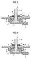
- the third and fourth embodiments of the present invention will be described hereinafter in connection with Figs. 7 and 8.
- the third embodiment differs from the first embodiment in that the surrounding wall 27 is tapered in such an arrangement that the diameter of the inner circumference increases towards the lower end thereof.
- the fourth embodiment differs from the first embodiment in that the pole 13 has a tapered outer circumference the diameter of which decreases toward the upper end. In accordance with any of these embodiments, when the nut 31 is tightened to pull up the pole 13, the upper portion of the pole 13 comes in close and firm contact with the inner surface of the surrounding wall 27.
- annular protrusion 25 and the surrounding wall 27 are made of, e.g., polypropylene, it will be apparent to those skilled in the art that the material of the annular protrusion 25 and the surrounding wall 27 is not specifically limited but may be a metal, polycarbonate, ABS, or polycarbonate/ABS.
- pole 15 is made of, e.g., Pb-Sn alloy
- the material of the pole 15 is not specifically limited so far as it is a deformable electrically-conductive material and may be pure lead or Pb-Sn alloy containing Se, Ag, As or the like.
Landscapes
- Chemical & Material Sciences (AREA)
- Chemical Kinetics & Catalysis (AREA)
- Electrochemistry (AREA)
- General Chemical & Material Sciences (AREA)
- Engineering & Computer Science (AREA)
- Manufacturing & Machinery (AREA)
- Sealing Battery Cases Or Jackets (AREA)
- Connection Of Batteries Or Terminals (AREA)
Abstract
Description
Claims (10)
- A sealed type lead acid battery comprising:wherein said female thread member is tightened so that said annular protrusion bites into the upper surface of said pole.a battery case which has an upper wall having a hole,an electrolytic solution contained in said battery case,an electrode contained in said battery case,an annular protrusion provided on the inner surface of said upper wall and surrounding the holes,a pole connected to said electrode and disposed beneath said hole,a male thread element having one end embedded in said pole and another end protruding from said pole to extend from the interior of said battery case to the exterior of said battery case through said hole, anda female thread member engaged with said male thread member at the portion thereof protruding from said upper wall,
- The sealed type lead acid battery according to Claim 1, wherein said male thread member acts as a terminal.
- The sealed type lead acid battery according to Claim 1 or 2, wherein said male thread member has a flange portion at one end thereof and said flange portion is embedded in said pole.
- The sealed type lead acid battery according to any one of Claims 1 to 3, which further comprises a surrounding wall on the inner surface of said upper wall the outer circumference of said pole and the inner circumference of said surrounding wall come in close contact with each other by tightening said female thread.
- The sealed type lead acid battery according to any one of Claims 1 to 4, wherein said pole is tapered such that the outer diameter decreases towards the upper end thereof.
- The sealed type lead acid battery according to Claim 4, wherein said surrounding wall is tapered such that the inner diameter increases towards the lower end thereof.
- The sealed type lead acid battery according to any one of Claims 1 to 6, wherein said pole comprises lead or lead alloy.
- The sealed type lead acid battery according to any one of Claims 1 to 7, which further comprises an elastic body interposed between said pole and the inner surface of said upper wall and disposed inside said annular protrusion.
- The sealed type lead acid battery according to Claim 8, wherein said elastic body is an O-ring.
- The sealed type lead acid battery according to any one of Claims 1 to 9, which comprises a plurality of said annular protrusions.
Applications Claiming Priority (2)
| Application Number | Priority Date | Filing Date | Title |
|---|---|---|---|
| JP2000267517 | 2000-09-04 | ||
| JP2000267517A JP2002075328A (en) | 2000-09-04 | 2000-09-04 | Sealed lead-acid battery |
Publications (2)
| Publication Number | Publication Date |
|---|---|
| EP1184916A2 true EP1184916A2 (en) | 2002-03-06 |
| EP1184916A3 EP1184916A3 (en) | 2004-02-18 |
Family
ID=18754429
Family Applications (1)
| Application Number | Title | Priority Date | Filing Date |
|---|---|---|---|
| EP01121176A Withdrawn EP1184916A3 (en) | 2000-09-04 | 2001-09-04 | Sealed type lead acid battery |
Country Status (4)
| Country | Link |
|---|---|
| US (1) | US20020039678A1 (en) |
| EP (1) | EP1184916A3 (en) |
| JP (1) | JP2002075328A (en) |
| CN (1) | CN1343021A (en) |
Cited By (3)
| Publication number | Priority date | Publication date | Assignee | Title |
|---|---|---|---|---|
| FR2888668A1 (en) * | 2005-07-13 | 2007-01-19 | Batscap Sa | ELECTRICAL BONDING TERMINAL FOR ELECTRIC ENERGY STORAGE CELL |
| US9368908B2 (en) | 2014-04-03 | 2016-06-14 | Akron Brass Company | Electrical terminal assembly |
| CN106816645A (en) * | 2017-04-10 | 2017-06-09 | 中和全盛(深圳)股份有限公司 | A kind of CNT is combined lead-acid battery |
Families Citing this family (11)
| Publication number | Priority date | Publication date | Assignee | Title |
|---|---|---|---|---|
| JP2003173767A (en) * | 2001-12-04 | 2003-06-20 | Nec Tokin Tochigi Ltd | Sealed battery |
| CN1331249C (en) * | 2002-12-25 | 2007-08-08 | 富士重工业株式会社 | Storage battery |
| KR100684743B1 (en) * | 2004-10-28 | 2007-02-20 | 삼성에스디아이 주식회사 | Secondary battery module |
| CN101383427B (en) * | 2008-10-17 | 2010-04-14 | 杜文达 | Method for converting chemical energy into electric energy |
| DE102009054639A1 (en) * | 2009-12-15 | 2011-06-16 | Robert Bosch Gmbh | Hand tool add-on module |
| CN102255063B (en) * | 2011-06-13 | 2013-07-03 | 江苏华富储能新技术股份有限公司 | Connecting method of power type batteries with internal screw-threaded polar posts |
| WO2013002173A1 (en) * | 2011-06-30 | 2013-01-03 | 三洋電機株式会社 | Sealed battery |
| DE102011054773A1 (en) * | 2011-10-25 | 2013-04-25 | Vb Autobatterie Gmbh & Co. Kgaa | Connection pole for a rechargeable battery, accumulator housing and machine for the production of a connection pole |
| WO2014042135A1 (en) * | 2012-09-13 | 2014-03-20 | 株式会社 豊田自動織機 | Power storage device |
| EP3734684A4 (en) * | 2017-12-27 | 2021-07-21 | Kabushiki Kaisha Toshiba | Secondary battery and method for restoring secondary battery |
| CN114039104B (en) * | 2021-09-24 | 2023-09-26 | 风帆(扬州)有限责任公司 | Leakage-proof valve-controlled lead-acid battery |
Family Cites Families (6)
| Publication number | Priority date | Publication date | Assignee | Title |
|---|---|---|---|---|
| FR1418682A (en) * | 1963-12-24 | 1965-11-19 | Oldham & Son Ltd | Improvements to the sealed assembly of the connection terminals in the battery covers of electric accumulators |
| US3839093A (en) * | 1972-09-25 | 1974-10-01 | Gates Rubber Co | Lead sealed-through connection |
| US5686202A (en) * | 1995-10-18 | 1997-11-11 | Hawker Energy Products, Inc. | Stress resistant battery configuration |
| US5834134A (en) * | 1995-10-18 | 1998-11-10 | Hawker Energy Products, Inc. | Sealant gasketing plastic nut battery terminal seal |
| JP3714428B2 (en) * | 1995-12-15 | 2005-11-09 | 株式会社ユアサコーポレーション | Lead acid battery terminal |
| JP2000231917A (en) * | 1999-02-09 | 2000-08-22 | Nec Mobile Energy Kk | Sealed battery |
-
2000
- 2000-09-04 JP JP2000267517A patent/JP2002075328A/en active Pending
-
2001
- 2001-08-31 US US09/942,767 patent/US20020039678A1/en not_active Abandoned
- 2001-09-04 EP EP01121176A patent/EP1184916A3/en not_active Withdrawn
- 2001-09-04 CN CN01131036A patent/CN1343021A/en active Pending
Cited By (5)
| Publication number | Priority date | Publication date | Assignee | Title |
|---|---|---|---|---|
| FR2888668A1 (en) * | 2005-07-13 | 2007-01-19 | Batscap Sa | ELECTRICAL BONDING TERMINAL FOR ELECTRIC ENERGY STORAGE CELL |
| WO2007006809A3 (en) * | 2005-07-13 | 2007-04-19 | Batscap Sa | Electrical connection terminal for electric power storage cell |
| US8025996B2 (en) | 2005-07-13 | 2011-09-27 | Batscap | Electrical connection terminal for electric power storage cell |
| US9368908B2 (en) | 2014-04-03 | 2016-06-14 | Akron Brass Company | Electrical terminal assembly |
| CN106816645A (en) * | 2017-04-10 | 2017-06-09 | 中和全盛(深圳)股份有限公司 | A kind of CNT is combined lead-acid battery |
Also Published As
| Publication number | Publication date |
|---|---|
| US20020039678A1 (en) | 2002-04-04 |
| JP2002075328A (en) | 2002-03-15 |
| CN1343021A (en) | 2002-04-03 |
| EP1184916A3 (en) | 2004-02-18 |
Similar Documents
| Publication | Publication Date | Title |
|---|---|---|
| EP1184916A2 (en) | Sealed type lead acid battery | |
| US5422201A (en) | Current collector assembly for an electrochemical cell | |
| JPWO2020149350A1 (en) | Sealed battery | |
| EP0320430A2 (en) | Bushing and gasket assembly | |
| WO2020137372A1 (en) | Sealed battery | |
| JP2000138055A (en) | Non-aqueous electrolyte battery | |
| JP2000138055A5 (en) | ||
| JP2012164637A (en) | Electric storage element | |
| JP4127618B2 (en) | Sealed battery | |
| US3964934A (en) | High discharge capability sealed through connector | |
| EP3447780B1 (en) | Electronic component | |
| JP4672041B2 (en) | Alkaline battery and alkaline battery sealing unit | |
| US5380603A (en) | Battery terminal seal | |
| JP3691268B2 (en) | Sealed battery | |
| JP2000215880A (en) | Battery | |
| JP4590911B2 (en) | battery | |
| US3839093A (en) | Lead sealed-through connection | |
| JP2006128010A (en) | Sealed battery | |
| US4385100A (en) | Terminal apparatus for electrolytic device | |
| JP2002289156A (en) | Storage battery | |
| KR19980702192A (en) | Thin battery | |
| EP0037121A1 (en) | Improvements in alkaline cells | |
| JP4540035B2 (en) | Battery and battery manufacturing method | |
| JPS59132558A (en) | battery | |
| US4295705A (en) | One piece connector |
Legal Events
| Date | Code | Title | Description |
|---|---|---|---|
| PUAI | Public reference made under article 153(3) epc to a published international application that has entered the european phase |
Free format text: ORIGINAL CODE: 0009012 |
|
| AK | Designated contracting states |
Kind code of ref document: A2 Designated state(s): AT BE CH CY DE DK ES FI FR GB GR IE IT LI LU MC NL PT SE TR |
|
| AX | Request for extension of the european patent |
Free format text: AL;LT;LV;MK;RO;SI |
|
| PUAL | Search report despatched |
Free format text: ORIGINAL CODE: 0009013 |
|
| AK | Designated contracting states |
Kind code of ref document: A3 Designated state(s): AT BE CH CY DE DK ES FI FR GB GR IE IT LI LU MC NL PT SE TR |
|
| AX | Request for extension of the european patent |
Extension state: AL LT LV MK RO SI |
|
| RIC1 | Information provided on ipc code assigned before grant |
Ipc: 7H 01M 2/08 B Ipc: 7H 01M 10/12 B Ipc: 7H 01M 2/06 A |
|
| AKX | Designation fees paid | ||
| REG | Reference to a national code |
Ref country code: DE Ref legal event code: 8566 |
|
| STAA | Information on the status of an ep patent application or granted ep patent |
Free format text: STATUS: THE APPLICATION IS DEEMED TO BE WITHDRAWN |
|
| 18D | Application deemed to be withdrawn |
Effective date: 20040819 |