EP1184768A2 - Thermal control apparatus and method for thermally controlling a plurality of objects within a predetermined temperature range - Google Patents
Thermal control apparatus and method for thermally controlling a plurality of objects within a predetermined temperature range Download PDFInfo
- Publication number
- EP1184768A2 EP1184768A2 EP01102589A EP01102589A EP1184768A2 EP 1184768 A2 EP1184768 A2 EP 1184768A2 EP 01102589 A EP01102589 A EP 01102589A EP 01102589 A EP01102589 A EP 01102589A EP 1184768 A2 EP1184768 A2 EP 1184768A2
- Authority
- EP
- European Patent Office
- Prior art keywords
- temperature
- thermal control
- heater
- heaters
- priority
- Prior art date
- Legal status (The legal status is an assumption and is not a legal conclusion. Google has not performed a legal analysis and makes no representation as to the accuracy of the status listed.)
- Granted
Links
Images


Classifications
-
- H—ELECTRICITY
- H02—GENERATION; CONVERSION OR DISTRIBUTION OF ELECTRIC POWER
- H02J—CIRCUIT ARRANGEMENTS OR SYSTEMS FOR SUPPLYING OR DISTRIBUTING ELECTRIC POWER; SYSTEMS FOR STORING ELECTRIC ENERGY
- H02J3/00—Circuit arrangements for AC mains or AC distribution networks
- H02J3/12—Circuit arrangements for AC mains or AC distribution networks for adjusting voltage in AC networks by changing a characteristic of the network load
- H02J3/14—Circuit arrangements for AC mains or AC distribution networks for adjusting voltage in AC networks by changing a characteristic of the network load by switching loads on to, or off from, network, e.g. progressively balanced loading
-
- G—PHYSICS
- G05—CONTROLLING; REGULATING
- G05D—SYSTEMS FOR CONTROLLING OR REGULATING NON-ELECTRIC VARIABLES
- G05D23/00—Control of temperature
- G05D23/19—Control of temperature characterised by the use of electric means
- G05D23/1927—Control of temperature characterised by the use of electric means using a plurality of sensors
- G05D23/193—Control of temperature characterised by the use of electric means using a plurality of sensors sensing the temperaure in different places in thermal relationship with one or more spaces
- G05D23/1932—Control of temperature characterised by the use of electric means using a plurality of sensors sensing the temperaure in different places in thermal relationship with one or more spaces to control the temperature of a plurality of spaces
- G05D23/1934—Control of temperature characterised by the use of electric means using a plurality of sensors sensing the temperaure in different places in thermal relationship with one or more spaces to control the temperature of a plurality of spaces each space being provided with one sensor acting on one or more control means
-
- H02J2105/52—
-
- H02J2105/54—
-
- Y—GENERAL TAGGING OF NEW TECHNOLOGICAL DEVELOPMENTS; GENERAL TAGGING OF CROSS-SECTIONAL TECHNOLOGIES SPANNING OVER SEVERAL SECTIONS OF THE IPC; TECHNICAL SUBJECTS COVERED BY FORMER USPC CROSS-REFERENCE ART COLLECTIONS [XRACs] AND DIGESTS
- Y02—TECHNOLOGIES OR APPLICATIONS FOR MITIGATION OR ADAPTATION AGAINST CLIMATE CHANGE
- Y02B—CLIMATE CHANGE MITIGATION TECHNOLOGIES RELATED TO BUILDINGS, e.g. HOUSING, HOUSE APPLIANCES OR RELATED END-USER APPLICATIONS
- Y02B70/00—Technologies for an efficient end-user side electric power management and consumption
- Y02B70/30—Systems integrating technologies related to power network operation and communication or information technologies for improving the carbon footprint of the management of residential or tertiary loads, i.e. smart grids as climate change mitigation technology in the buildings sector, including also the last stages of power distribution and the control, monitoring or operating management systems at local level
- Y02B70/3225—Demand response systems, e.g. load shedding, peak shaving
-
- Y—GENERAL TAGGING OF NEW TECHNOLOGICAL DEVELOPMENTS; GENERAL TAGGING OF CROSS-SECTIONAL TECHNOLOGIES SPANNING OVER SEVERAL SECTIONS OF THE IPC; TECHNICAL SUBJECTS COVERED BY FORMER USPC CROSS-REFERENCE ART COLLECTIONS [XRACs] AND DIGESTS
- Y04—INFORMATION OR COMMUNICATION TECHNOLOGIES HAVING AN IMPACT ON OTHER TECHNOLOGY AREAS
- Y04S—SYSTEMS INTEGRATING TECHNOLOGIES RELATED TO POWER NETWORK OPERATION, COMMUNICATION OR INFORMATION TECHNOLOGIES FOR IMPROVING THE ELECTRICAL POWER GENERATION, TRANSMISSION, DISTRIBUTION, MANAGEMENT OR USAGE, i.e. SMART GRIDS
- Y04S20/00—Management or operation of end-user stationary applications or the last stages of power distribution; Controlling, monitoring or operating thereof
- Y04S20/20—End-user application control systems
- Y04S20/222—Demand response systems, e.g. load shedding, peak shaving
Definitions
- the present invention relates to a thermal control apparatus for applying simultaneous thermal control to a plurality of objects using heaters or the like, a space craft provided with said thermal control apparatus, and a thermal control method.
- the present invention relates to thermal control for an artificial satellite, a space station, or a space craft such as a transporter for space navigation.
- Fig. 6 schematically shows a conventional thermal control system for an artificial satellite.
- the system includes a power source 1, and a calculator 6 for determining/instructing ON/OFF of heaters 3, as will be described below.
- the calculator 6 includes a heater ON/OFF determining circuit 7 for the heaters 3.
- a plurality of thermal control objects 2 1 , 2 2 , 2 3 ... 2 i ... (hereinafter will be referred to as "objects") are installed in an artificial satellite.
- the object 2 may include, for example, an electronic device for attitude control, communication, data processing, power supply or the like, a propeller device, and an antenna device, which are disposed in the satellite structure.
- step S1 the temperature Ti of each object 2i is measured using the temperature sensor 4i mounted on the object 2i.
- step S2 the temperature Ti is compared with the lower limit control temperature Tia of the object 2i.
- the calculator 6 instructs the switch 5i to be ON according to step S3, so that the heater 3i is turned on to raise the temperature Ti.
- the temperature Ti is further compared with the upper limit control temperature Tib of the object 2i at step 4.
- the calculator 6 instructs the switch 5i to be OFF according to step S5, such that the heater 3i is turned off to thereby reduce the temperature Ti of the object 2i.
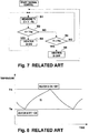
- the temperature Ti of the object 2i is controlled within a range approximately between Tia and Tib, as shown in Fig. 8.
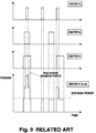
- Fig. 9 illustrates an example when three objects are thermally controlled by means of three heaters, respectively.
- the average power of the three heaters is indicated by a dotted line.
- thermal control should be possible as long as power corresponding to the average power is continuously consumed by the heaters.
- a significantly large peak power is produced by simultaneously actuating a plurality of heaters, which adversely affects a power system of the artificial satellite.
- the power system of the satellite must be designed so that it can supply power sufficient to cover such peak periods, but doing so introduces significant disadvantages regarding weight or cost of the satellite resulting from including such a power source with large maximum supply capacity.
- the present invention was made so as to solve the above problems of the conventional thermal control for an artificial satellite or the like, and aims to reduce the peak energy (maximum energy) which must be supplied to heaters or coolers, which is produced when a plurality of heaters and coolers are simultaneously actuated.
- a thermal control apparatus comprising a plurality of heaters and/or coolers each controlled to be ON and OFF for changing a temperature of each of a plurality of thermal control objects; a plurality of temperature sensors each provided in each of said plurality of thermal control objects for measuring the temperature of said thermal control object and outputting the measured temperature; a heater and/or cooler ON/OFF priority reading table which, in response to input of said measured temperature, outputs priority for turning on said plurality of heaters and/or coolers, based on order values for turning on said plurality of heaters and/or coolers, predetermined in correspondence with temperature, and said measured temperature; and an energy managing section for turning on the heater or the cooler with high priority and turning off the heater or the cooler with low priority based on said priority output from said ON/OFF priority reading table, such that a sum of energy supplied for actuating said plurality of heaters or coolers does not exceed an energy limit.
- each of said order values is determined for every plurality of temperature levels within a temperature control range established for each of said plurality of thermal control objects.
- said priority is determined based on the speed of temperature response of said plurality of thermal control objects.
- higher priority is assigned to a heater or cooler of a thermal control object with higher speed of temperature response and to a heater or cooler of a thermal control object whose measured temperature is more approximate to a lower limit.
- said temperature control range includes a level of upper limit approximate temperature adjoining the upper limit of said temperature control range, and when said measured temperature falls within said level of upper limit approximate temperature, the heater or the cooler provided in the thermal control object having said measured temperature is turned off.
- said temperature control range includes a level of OFF maintaining temperature, such that, when said measured temperature falls within said level of OFF maintaining temperature and a heater or cooler provided in the thermal control object having said measured temperature is in an off state, the heater or cooler is controlled to be maintained in an off state.
- the upper limit of said level of OFF maintaining temperature adjoins the lower limit of said level of upper limit approximate temperature.
- said energy limit is set to be slightly greater than the average energy level for said heaters or coolers in operation.
- a space craft provided with said thermal control apparatus for thermally controlling a plurality of thermal control objects.
- a thermal control method for controlling a plurality of heaters and/or coolers controlled to be ON and OFF for changing the temperature of each of the thermal control object, the temperature of each of said plurality of thermal control objects being measured by one of a plurality of sensors, said thermal control method comprising a first step of determining priority for turning on said heaters or coolers based on said measured temperature; a second step of sequentially adding energy supplied for turning the heater or the cooler on, in the order starting from a heater or a cooler with higher priority of the heaters or the coolers whose priority is determined in said first step; and a third step of sequentially comparing the sum of energy sequentially added in said second step with an energy limit and, when the sum of energy exceeds said energy limit, turning on the heaters or the coolers corresponding to the energy which was added immediately before the time when the energy limit is exceeded, wherein said first, second, and third steps are repeatedly executed.
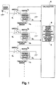
- Fig. 1 shows a structure of the thermal control apparatus according to one embodiment of the present invention.
- the apparatus includes a power source 1, and a calculator 6 for determining ON/OFF instruction of heaters 3 (which will be described later).
- the calculator 6 further includes an heater ON/OFF priority determining circuit 8 for the heaters 3, which functions as a heater and/or cooler ON/OFF priority output circuit, and a heater peak power managing section 9.
- Each of N thermal control objects 2 1 , 2 2 , 2 3 ... 2 i ... (hereinafter will be referred to as "objects") (N ⁇ 2) is provided with a heater 3 1 , 3 2 , 3 3 ... 3 i ..., a temperature sensor 4 1 , 4 2 , 4 3 ...
- numerals 2 - 5 have subscripts 1, 2, 3, ... i ... in this order from the top, to indicate that a plurality of elements are provided.
- the heater ON/OFF priority determining circuit 8 selects candidate heaters to be turned on, and interprets the priority from the order values for turning on heaters, as determined according to the heater ON/OFF priority determining logic installed therein. Then, according to a heater peak power managing logic installed in the heater peak power managing section 9, the heater peak power managing section 9 determines the heaters to be actually turned on, based on the priority determined by the ON/OFF priority determining circuit 8, such that the peak power (maximum power) which is sum of the power consumed by the turned-on heaters does not exceed a limit, and turns the selected heaters on.
- the limit of peak power (maximum power) by all the turned-on heaters must be greater than the average power of the total heaters, the limit can be approximate to the average power due to balance of heat. Accordingly, by setting the limit of the peak power (maximum power) by the total heaters to be slightly greater than the average power thereof, the total power of a plurality of heaters 3 varies in the vicinity of the average power as shown in Fig. 5, so that the peak power (maximum power of the total heaters) can be reduced to a level which is only slightly greater than the average power thereof.
- FIG. 2 and 3 examples of the heater ON/OFF priority determining logic in the ON/OFF priority determining circuit 8 and of the heater peak power managing logic in the heater peak power managing section 9 according to this embodiment are illustrated. The specific operation according to these logic will now be with reference to Figs. 1 to 3.
- Fig. 2 one example of order determination in the heater ON/OFF priority determining logic will be described.
- an order is assigned for each heater regarding turning on, based on temperature response of the thermal control object and a difference ⁇ t in temperature between the temperature of the object and the minimum temperature required for turning the heater 3 on (which corresponds to the temperature Tia in the example shown in Fig.8).
- circled numerals 1 ⁇ , 2 ⁇ , 3 ⁇ ,... 9 ⁇ indicate order values.
- the temperature at which the heater 3 is turned on is shifted from the temperature at which the heater 3 is turned off, so that the heater 3 is switched on and off relatively infrequently.
- the heater 3 maintains the current status as long as the conditions of the heater peak power managing logic, which will be described later, are satisfied. (Specifically, as a rule, the heater which is currently ON remains ON, while the heater which is currently OFF remains OFF)
- the hysteresis region as described herein is a level of "OFF maintaining temperature". Inclusion of the level of "OFF maintaining temperature" in the temperature control range leads to advantages such as, for example, elimination of unnecessary power consumption and reduction in operation performed by a heater peak power managing section, as will be described later.
- ⁇ T is selected so as to satisfy Tia + 3 ⁇ T ⁇ Tib, where Tia represents a lower limit control temperature which means a limit in the lower temperature within a temperature control range of the thermal control object 2i when performing thermal control by means of heaters, and Tib represents an upper limit control temperature which means a limit in the higher temperature within a temperature control range of the thermal control object 2i when performing thermal control by means of heaters.
- Numeral value "3" in the above expression may appropriately be replaced with other numeral values such that optimum control can be performed in accordance with the number and the temperature range of heaters, as well as temperature response.
- the ON/OFF priority determining circuit 8 comprises a digital circuit configured such that digital data which is converted from the temperature of a thermal control object 2i measured by the temperature sensor 4i by means of an A/D converter are input to a data base which stores a table shown in Fig. 2 for example, and the information on the priority of the corresponding heater 3i are output, or a logic circuit configured such that a signal which identifies a thermal control object 2i and a temperature value of the thermal control object 2i measured by the temperature sensor 4i are input therein and information on the priority are output.
- the ON/OFF priority determining circuit 8 reads that the order value is 5 ⁇ from the table shown in Fig. 2, and determines that the heater 3 1 is a candidate to be turned on due to the temperature difference ⁇ t from Tia being ⁇ T - 2 ⁇ T.
- the ON/OFF priority determining circuit 8 interprets that the temperature difference ⁇ t from Tia falls within 2 ⁇ T ⁇ 3 ⁇ T and determines that the heater 3 2 is to be turned off.
- the ON/OFF priority determining circuit 8 uses the order values to determine the priority of the heater, such as, for example, the heater 3 1 this priority indicating an order in which the heaters are to be turned on.
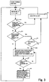
- step S11 the temperature Ti of each thermal control object 2i is measured by the temperature sensor 4i.
- a heater to be turned off is determined according to the heater ON/OFF priority determining logic of Fig. 2 at step S12, and the heater 3i is turned off at step S13.
- the heater 3i which is determined not to be OFF (namely, ON or hysteresis in Fig. 2) according to the heater ON/OFF priority determining logic of Fig. 2
- step S14 it is determined at step S14 if the heater 3i is in a hysteresis state.
- the heater 3i remains OFF.
- the order values of the heaters 3 1 , 3 2 , 3 3 according to the logic of Fig. 2 are 2 ⁇ , 9 ⁇ and OFF, respectively. Accordingly, the priority of the candidate heaters 3j to be turned on are, in order, heater 3 1 (order value 2 ⁇ ) and heater 3 2 (order value 9 ⁇ ).
- the heater power Pj of each of the candidate heaters 3j is calculated using a voltage V and resistance Rj thereof according to the following expression (1).
- Pj V 2 /Rj
- the total power Pt of the heaters with order values 1 ⁇ to m h is added in order of the priority as shown in the following expression (2).
- Pt ⁇ Pj( 1 ) + ⁇ Pj( 2 ) + ... + ⁇ Pj(m h )
- step S17 it is determined when the total power Pt of the heaters obtained by sequentially adding the heater power of each candidate heater 3j in the priority order exceeds the limit value Pl of the peak power (maximum power), and the value of order value m h of the heater whose addition caused the power to exceed the limit is determined.
- step S18 the heaters 3j with order values 1 ⁇ to m (h-1) , which is one before the order value m h , are turned on whereas the heaters 3j with the order value m h and after that are turned off.
- the total power Pt of the heaters falls within the limit Pl as indicated by the following expression (3), and a series of heater ON/OFF setting operations by means of the heater ON/OFF priority determining logic and the peak power managing logic are completed.
- Pt ⁇ Pj( 1 ) + ⁇ Pj( 2 ) + ... + ⁇ Pj(m (h-1) ) ⁇ Pl (wherein it is assumed a sum of the heater power of heaters 3j with order value 1 ⁇ is ⁇ Pj(1 ⁇ ), a sum of the heater power of heaters 3j with order value 2 ⁇ is ⁇ Pj(2 ⁇ ), and a sum of the heater power of heaters 3j with order value m h is ⁇ Pj(m h ))
- Fig. 4 shows the temperature response when one example of thermal control of the present invention is performed for a thermal control object with medium temperature response in Fig. 2.
- ON/OFF of the heaters is generally performed sufficiently within the range of Tia ⁇ Tib and the temperature of the thermal control objects also falls sufficiently within the range of Tia ⁇ Tib.
- the heater is not turned on until the temperature drops to Tia and must be always turned on once the temperature drops to Tia.
- the heaters are allowed to be turned on before the temperature drops to Tia, in which case the heaters need not necessarily be turned on, and it is therefore possible to provide a significant degree of freedom for ON/OFF of the heaters.
- the heaters can be turned on according to a priority, even before the temperature drops to Tia. Contrary to this, when the total power Pt exceeds the limit value P1 of the peak power (maximum power), the heaters can be turned off in the reversed order of priority.
- the total heater power Pt is controlled to fall within a limit P1 of the peak power (maximum power) which is set to be slightly greater than the average power of the heaters while providing great degree of freedom for heater ON/OFF. Because of this, the total heater power Pt varies within a range near the average power as shown in Fig. 5. While in the conventional system, the peak power (maximum power) is significantly greater than the average power as shown in Fig. 9, in the present invention, the peak power (maximum power) can be reduced to a level only slightly greater than the average power as shown in Fig. 5.
- the present invention it is therefore possible to reduce the heater peak power (maximum power) required for thermally controlling a space craft such as an artificial satellite, which leads to a reduction in the maximum power of the power system of the space craft which supplies power to the heaters, thereby simplifying the design of the power system.
- This advantage also results in a reduction in the weight of a power source to be installed on a space craft while lowering cost.
- heater ON/OFF priority determining logic as shown in Fig. 2 is used in the foregoing example, other logic may alternatively be used as long as such logic satisfies the requirements of the invention.
- many of the heaters may be assigned in the same rank of temperature response when the above-described three-level ranking is adopted. If this is the case, the temperature response may be subdivided into four or more ranks. Alternatively, items in the same rank may be further ranked according to another criteria. (For example, another three-level ranking is further applied in the same rank, such that an order of 1 ⁇ -1, 1 ⁇ -2, 1 ⁇ -3, 2 ⁇ -1, 2 ⁇ -2, 2 ⁇ -3, ... 9 ⁇ -1, 9 ⁇ -2, 9 ⁇ -3 is set.)
- heaters are used as a heat source for thermal control.
- the present invention is applicable to other types of heating apparatuses using electrical power. Further, the concept of the present invention is also applicable to thermal control by means of a cooling apparatus using an electrical power, to thereby reduce the peak power of the cooling apparatus.
- the above-mentioned lower limit control temperature Tia means the limit in the higher temperature within a temperature control range of the thermal control object 2i, and the term "lower limit" refers to "the limit value of higher temperature”.
- the above-mentioned upper limit control temperature Tib means the limit in the lower temperature within a temperature control range of the thermal control object 2i, and the term “upper limit” refers to "the limit value of lower temperature".
- ⁇ T is selected such that it satisfies Tia - 3 ⁇ T ⁇ Tib.
- numeral value 3 in the foregoing expression may be appropriately replaced with other numeral values such that optimum control can be performed in accordance with the number and the temperature range of coolers as well as temperature response.
- the foregoing example described reduction in peak power of a thermal control apparatus to which electrical power is supplied as energy.
- the concept of the present invention is also applicable to reduction in the peak amount of other energy to be supplied such as gas or petroleum.
Landscapes
- Engineering & Computer Science (AREA)
- Power Engineering (AREA)
- Remote Sensing (AREA)
- Physics & Mathematics (AREA)
- General Physics & Mathematics (AREA)
- Automation & Control Theory (AREA)
- Control Of Temperature (AREA)
- Control Of Resistance Heating (AREA)
Abstract
Description
Claims (10)
- A thermal control apparatus comprising:a plurality of heaters and/or coolers each controlled to be on and off for changing a temperature of each of a plurality of thermal control objects;for each of said plurality of thermal control objects, a temperature sensor for measuring the temperature of the thermal control object and for outputting the measured temperature;a heater and/or cooler ON/OFF priority reading table which, in response to input of said measured temperature, outputs a priority for turning on each of said plurality of heaters and/or coolers, based on said measured temperature and a predetermined order value for turning on said plurality of heaters and/or coolers in correspondence with temperature; andan energy managing section for turning on a heater or cooler with high priority and turning off a heater or cooler with low priority based on said priority output from said ON/OFF priority reading table, such that the sum of energy supplied for actuating said plurality of heaters or coolers does not exceed a predetermined energy limit.
- A thermal control apparatus according to claim 2, wherein said order values are determined for each of a plurality of temperature levels within a temperature control range established for each of said plurality of thermal control objects.
- A thermal control apparatus according to claim 1, wherein said priority is determined based on the speed of temperature response of said plurality of thermal control objects.
- A thermal control apparatus according to claim 3, wherein higher priority is assigned to a heater or cooler of a thermal control object with higher speed of temperature response and to a heater or cooler of a thermal control object whose measured temperature is more approximate to a lower limit.
- A thermal control apparatus according to claim 2, wherein said temperature control range includes a level of upper limit approximate temperature adjoining the upper limit of said temperature control range, and when said measured temperature falls within said level of upper limit approximate temperature, a heater or cooler provided in the thermal control object having said measured temperature is turned off.
- A thermal control apparatus according to claim 2, wherein said temperature control range includes a level of OFF maintaining temperature, such that, when said measured temperature falls within said level of OFF maintaining temperature and a heater or cooler provided in the thermal control object having said measured temperature is in an off state, the heater or cooler is controlled to be maintained in an off state.
- A thermal control apparatus according to claim 6, wherein the upper limit of said level of OFF maintaining temperature adjoins the lower limit of said level of upper limit approximate temperature.
- A thermal control apparatus according to claims 1 to 7, wherein said energy limit is set to be slightly greater than the average energy level for said heaters or coolers in operation.
- A space craft provided with a thermal control apparatus according to claims 1 to 8 for thermally controlling a plurality of thermal control objects.
- A thermal control method for controlling a plurality of heaters and/or coolers and controlled to be on and off for changing the temperature of the thermal control object, the temperature of each of said plurality of thermal control objects being measured by each of a plurality of sensors, said thermal control method comprising:wherein said first, second, and third steps are repeatedly executed.a first step of determining priority for turning on said heaters or coolers based on said measured temperature;a second step of sequentially adding energy supplied for turning the heater or the cooler on, in the order starting from a heater or a cooler with higher priority of the heaters or the coolers whose priority is determined in said first step; anda third step of sequentially comparing the sum of energy sequentially added in said second step with an energy limit and, when the sum of energy exceeds said energy limit, turning on the heaters or the coolers corresponding to the energy which was added immediately before the time when the energy limit is exceeded,
Applications Claiming Priority (2)
| Application Number | Priority Date | Filing Date | Title |
|---|---|---|---|
| JP2000265499 | 2000-09-01 | ||
| JP2000265499A JP3852555B2 (en) | 2000-09-01 | 2000-09-01 | Thermal control device, spacecraft, and thermal control method |
Publications (3)
| Publication Number | Publication Date |
|---|---|
| EP1184768A2 true EP1184768A2 (en) | 2002-03-06 |
| EP1184768A3 EP1184768A3 (en) | 2003-12-03 |
| EP1184768B1 EP1184768B1 (en) | 2005-11-16 |
Family
ID=18752754
Family Applications (1)
| Application Number | Title | Priority Date | Filing Date |
|---|---|---|---|
| EP01102589A Expired - Lifetime EP1184768B1 (en) | 2000-09-01 | 2001-02-06 | Thermal control apparatus and method for thermally controlling a plurality of objects within a predetermined temperature range |
Country Status (4)
| Country | Link |
|---|---|
| US (1) | US6566633B2 (en) |
| EP (1) | EP1184768B1 (en) |
| JP (1) | JP3852555B2 (en) |
| DE (1) | DE60114955T2 (en) |
Cited By (13)
| Publication number | Priority date | Publication date | Assignee | Title |
|---|---|---|---|---|
| EP1980925A1 (en) * | 2007-04-13 | 2008-10-15 | Océ-Technologies B.V. | Method and control unit for controlling the power supplied to a plurality of heat sources in a printer |
| WO2008125875A2 (en) | 2007-04-13 | 2008-10-23 | Basic Device Limited | Radiators |
| US7884498B2 (en) | 2004-09-24 | 2011-02-08 | Meiko Maschinenbau Gmbh & Co Kg | Method and arrangement for the energy-saving operation of dishwashers |
| US8182233B2 (en) | 2007-07-13 | 2012-05-22 | Rolls-Royce Plc | Component with a damping filler |
| US8241004B2 (en) | 2008-05-15 | 2012-08-14 | Rolls-Royce, Plc | Component structure |
| US8365388B2 (en) | 2009-01-28 | 2013-02-05 | Rolls-Royce Plc | Method of joining plates of material to form a structure |
| US8529720B2 (en) | 2008-07-24 | 2013-09-10 | Rolls-Royce, Plc | Aerofoil sub-assembly, an aerofoil and a method of making an aerofoil |
| WO2013098362A3 (en) * | 2011-12-29 | 2013-09-26 | Welltec A/S | An electrical power distribution method for a wireline tool string downhole |
| US8701286B2 (en) | 2010-06-02 | 2014-04-22 | Rolls-Royce Plc | Rotationally balancing a rotating part |
| US8920893B2 (en) | 2009-01-27 | 2014-12-30 | Rolls-Royce Plc | Article with an internal structure |
| US8986490B2 (en) | 2010-11-26 | 2015-03-24 | Rolls-Royce Plc | Method of manufacturing a component |
| EP2560260A4 (en) * | 2010-03-24 | 2015-06-10 | Rkc Instruments Inc | MULTICANAL POWER REGULATOR |
| CN104755176A (en) * | 2012-10-25 | 2015-07-01 | 格瑞克明尼苏达有限公司 | Power management for hot melt dispensing systems |
Families Citing this family (18)
| Publication number | Priority date | Publication date | Assignee | Title |
|---|---|---|---|---|
| JP2003015746A (en) * | 2001-06-29 | 2003-01-17 | Nec Eng Ltd | Heater control system |
| FR2835805B1 (en) * | 2002-02-14 | 2004-06-18 | Cit Alcatel | SATELLITE DEVICE HAVING POWER SUPPLY MEANS AND ASSOCIATED WITH HEATING MEANS |
| US7041940B2 (en) * | 2003-03-28 | 2006-05-09 | General Electric Company | Power management systems and methods |
| US20060106503A1 (en) * | 2004-11-16 | 2006-05-18 | Astronics Advanced Electronic Systems Corp., A Corporation Of The State Of Washington | Method and system for thermal management |
| JP4758716B2 (en) * | 2005-09-16 | 2011-08-31 | 株式会社タムラ製作所 | Control method of heating device |
| RU2304071C2 (en) * | 2005-10-11 | 2007-08-10 | Открытое акционерное общество "Ракетно-космическая корпорация "Энергия" имени С.П. Королева" | Method of control of temperature of spacecraft onboard equipment |
| JP4793694B2 (en) * | 2007-04-18 | 2011-10-12 | 株式会社安川電機 | Robot control method, robot control apparatus, and robot control system |
| GB2449651A (en) * | 2007-05-29 | 2008-12-03 | Ultra Electronics Ltd | Power control system to reduce imbalances |
| JP6114074B2 (en) * | 2012-03-14 | 2017-04-12 | 株式会社半導体エネルギー研究所 | Power supply system |
| US9362749B2 (en) * | 2012-04-20 | 2016-06-07 | Battelle Memorial Institute | Controller for thermostatically controlled loads |
| JP6282235B2 (en) * | 2015-01-28 | 2018-02-21 | 三菱電機株式会社 | Heater control device and heater control method |
| US20210190380A1 (en) * | 2016-03-02 | 2021-06-24 | Watlow Electric Manufacturing Company | Heater bundles having virtual sensing for thermal gradient compensation |
| US12270577B2 (en) * | 2016-03-02 | 2025-04-08 | Watlow Electric Manufacturing Company | Heater bundles for thermal gradient compensation |
| US10247445B2 (en) * | 2016-03-02 | 2019-04-02 | Watlow Electric Manufacturing Company | Heater bundle for adaptive control |
| US12540757B2 (en) * | 2016-03-02 | 2026-02-03 | Watlow Electric Manufacturing Company | Heater bundles with local power switching |
| US10619888B2 (en) * | 2016-03-02 | 2020-04-14 | Watlow Electric Manufacturing Company | Heater bundle for adaptive control and method of reducing current leakage |
| US20210190378A1 (en) * | 2016-03-02 | 2021-06-24 | Watlow Electric Manufacturing Company | Heater bundles having variable power output within zones |
| CN120485343A (en) | 2017-01-04 | 2025-08-15 | 深圳华大智造科技股份有限公司 | Sequencing by step of unlabeled reversible terminators or natural nucleotides |
Family Cites Families (8)
| Publication number | Priority date | Publication date | Assignee | Title |
|---|---|---|---|---|
| CA1070001A (en) * | 1976-02-06 | 1980-01-15 | Adrien Leroux | Control system to check power consumption of an electric distribution network |
| US4090062A (en) * | 1976-07-12 | 1978-05-16 | Phillips Control Corp. | Energy demand controller and method therefor |
| US4160153A (en) * | 1977-06-24 | 1979-07-03 | Pako Corporation | Duty cycle shared proportional temperature control |
| US4337401A (en) * | 1981-01-23 | 1982-06-29 | Honeywell Inc. | Adaptive load shedding |
| IT1218021B (en) * | 1988-05-27 | 1990-03-30 | Curti Di Curti Pietro & C S N | POWER REGULATOR FOR INDUSTRIAL PLANTS, IN PARTICULAR FOR ELECTRIC OVENS |
| JPH045200A (en) * | 1990-04-20 | 1992-01-09 | Toshiba Corp | Heater power controller |
| DE19651484A1 (en) * | 1996-12-11 | 1998-06-18 | Thomas Warnecke | Power consumption optimising method for system of electrically heated and cooled loads esp. for industrial applications |
| US6157008A (en) * | 1999-07-08 | 2000-12-05 | Maytag Corporation | Power distribution system for an appliance |
-
2000
- 2000-09-01 JP JP2000265499A patent/JP3852555B2/en not_active Expired - Fee Related
-
2001
- 2001-02-06 EP EP01102589A patent/EP1184768B1/en not_active Expired - Lifetime
- 2001-02-06 DE DE60114955T patent/DE60114955T2/en not_active Expired - Lifetime
- 2001-02-13 US US09/781,230 patent/US6566633B2/en not_active Expired - Fee Related
Cited By (19)
| Publication number | Priority date | Publication date | Assignee | Title |
|---|---|---|---|---|
| US7884498B2 (en) | 2004-09-24 | 2011-02-08 | Meiko Maschinenbau Gmbh & Co Kg | Method and arrangement for the energy-saving operation of dishwashers |
| EP1980925A1 (en) * | 2007-04-13 | 2008-10-15 | Océ-Technologies B.V. | Method and control unit for controlling the power supplied to a plurality of heat sources in a printer |
| WO2008125875A2 (en) | 2007-04-13 | 2008-10-23 | Basic Device Limited | Radiators |
| US7971955B2 (en) | 2007-04-13 | 2011-07-05 | Oce-Technologies B.V. | Method and control unit for controlling the power supplied to a plurality of heat sources in a printer |
| WO2008125875A3 (en) * | 2007-04-13 | 2012-02-02 | Basic Device Limited | Radiators |
| US8381398B2 (en) | 2007-07-13 | 2013-02-26 | Rolls-Royce Plc | Component with a damping filler and method |
| US8182233B2 (en) | 2007-07-13 | 2012-05-22 | Rolls-Royce Plc | Component with a damping filler |
| US8857054B2 (en) | 2007-07-13 | 2014-10-14 | Rolls-Royce Plc | Method of forming an aerofoil with a damping filler |
| US8241004B2 (en) | 2008-05-15 | 2012-08-14 | Rolls-Royce, Plc | Component structure |
| US8529720B2 (en) | 2008-07-24 | 2013-09-10 | Rolls-Royce, Plc | Aerofoil sub-assembly, an aerofoil and a method of making an aerofoil |
| US8920893B2 (en) | 2009-01-27 | 2014-12-30 | Rolls-Royce Plc | Article with an internal structure |
| US8365388B2 (en) | 2009-01-28 | 2013-02-05 | Rolls-Royce Plc | Method of joining plates of material to form a structure |
| EP2560260A4 (en) * | 2010-03-24 | 2015-06-10 | Rkc Instruments Inc | MULTICANAL POWER REGULATOR |
| US8701286B2 (en) | 2010-06-02 | 2014-04-22 | Rolls-Royce Plc | Rotationally balancing a rotating part |
| US8986490B2 (en) | 2010-11-26 | 2015-03-24 | Rolls-Royce Plc | Method of manufacturing a component |
| CN103987914A (en) * | 2011-12-29 | 2014-08-13 | 韦尔泰克有限公司 | Power distribution method for downhole wireline tool strings |
| WO2013098362A3 (en) * | 2011-12-29 | 2013-09-26 | Welltec A/S | An electrical power distribution method for a wireline tool string downhole |
| CN104755176A (en) * | 2012-10-25 | 2015-07-01 | 格瑞克明尼苏达有限公司 | Power management for hot melt dispensing systems |
| CN104755176B (en) * | 2012-10-25 | 2017-08-25 | 固瑞克明尼苏达有限公司 | Power management for hot melt distribution systems |
Also Published As
| Publication number | Publication date |
|---|---|
| JP2002075592A (en) | 2002-03-15 |
| EP1184768B1 (en) | 2005-11-16 |
| US6566633B2 (en) | 2003-05-20 |
| DE60114955D1 (en) | 2005-12-22 |
| US20020027131A1 (en) | 2002-03-07 |
| EP1184768A3 (en) | 2003-12-03 |
| JP3852555B2 (en) | 2006-11-29 |
| DE60114955T2 (en) | 2006-08-10 |
Similar Documents
| Publication | Publication Date | Title |
|---|---|---|
| EP1184768A2 (en) | Thermal control apparatus and method for thermally controlling a plurality of objects within a predetermined temperature range | |
| US9405352B2 (en) | Battery module, computer system having the same, and control method of the computer system | |
| JP3230960B2 (en) | Variable frequency clock controller for microprocessor based computer systems. | |
| US7608942B2 (en) | Power management system | |
| US7085943B2 (en) | Method and circuitry for controlling supply voltage in a data processing system | |
| US7777554B2 (en) | Method and apparatus for detecting temperatures of a plurality of circuits and controlling operations based on the detected temperatures | |
| US20090039842A1 (en) | Dc-dc converter | |
| EP1469370A2 (en) | Power-save computing apparatus, method and program | |
| US6363266B1 (en) | Electronic device | |
| TW200400693A (en) | Altering operating frequency and voltage set point of a circuit in response to the operating temperature and instantaneous operating voltage of the circuit | |
| US6366475B2 (en) | Power control method and circuit, and power supply unit | |
| US7841837B2 (en) | Cooling-fan rotation-speed control circuit | |
| RU2004126683A (en) | METHOD AND DEVICE FOR REGULATING TRANSMISSION OF ENERGY BETWEEN THE ENERGY TIRE WITH THE BATTERY SYSTEM IN ACCORDANCE WITH THE OPERATING CONDITION OF THE BATTERY | |
| EP0935184A2 (en) | Information processing apparatus, mode control method and storage medium | |
| US20060187731A1 (en) | Semiconductor memory device | |
| WO2007134096A1 (en) | Load circuit supply voltage control | |
| KR20190055873A (en) | Display panel driving device and display apparatus having the same | |
| JP2011078276A (en) | Charging controller and charging control method in charging controller | |
| US7321973B2 (en) | System for controlling power to a system part using a control unit and wherein the power to the control unit is controlled using a power controller | |
| US8628310B2 (en) | Fan system having improved availability and method for its operation | |
| US5880576A (en) | Charging apparatus for controlling supplement of electric current to a rechargeable battery | |
| US9605873B2 (en) | Heater with energy-saving operations and method related thereto | |
| US6281738B1 (en) | Bus driver, output adjusting method and driver | |
| US6870778B2 (en) | Semiconductor device including a voltage monitoring circuit | |
| US20050268128A1 (en) | Heat dissipation device and control method for same |
Legal Events
| Date | Code | Title | Description |
|---|---|---|---|
| PUAI | Public reference made under article 153(3) epc to a published international application that has entered the european phase |
Free format text: ORIGINAL CODE: 0009012 |
|
| AK | Designated contracting states |
Kind code of ref document: A2 Designated state(s): AT BE CH CY DE DK ES FI FR GB GR IE IT LI LU MC NL PT SE TR |
|
| AX | Request for extension of the european patent |
Free format text: AL;LT;LV;MK;RO;SI |
|
| PUAL | Search report despatched |
Free format text: ORIGINAL CODE: 0009013 |
|
| AK | Designated contracting states |
Kind code of ref document: A3 Designated state(s): AT BE CH CY DE DK ES FI FR GB GR IE IT LI LU MC NL PT SE TR |
|
| AX | Request for extension of the european patent |
Extension state: AL LT LV MK RO SI |
|
| 17P | Request for examination filed |
Effective date: 20031219 |
|
| 17Q | First examination report despatched |
Effective date: 20040511 |
|
| AKX | Designation fees paid |
Designated state(s): DE FR |
|
| GRAP | Despatch of communication of intention to grant a patent |
Free format text: ORIGINAL CODE: EPIDOSNIGR1 |
|
| GRAS | Grant fee paid |
Free format text: ORIGINAL CODE: EPIDOSNIGR3 |
|
| GRAA | (expected) grant |
Free format text: ORIGINAL CODE: 0009210 |
|
| AK | Designated contracting states |
Kind code of ref document: B1 Designated state(s): DE FR |
|
| REF | Corresponds to: |
Ref document number: 60114955 Country of ref document: DE Date of ref document: 20051222 Kind code of ref document: P |
|
| RAP2 | Party data changed (patent owner data changed or rights of a patent transferred) |
Owner name: MITSUBISHI DENKI KABUSHIKI KAISHA |
|
| ET | Fr: translation filed | ||
| PLBE | No opposition filed within time limit |
Free format text: ORIGINAL CODE: 0009261 |
|
| STAA | Information on the status of an ep patent application or granted ep patent |
Free format text: STATUS: NO OPPOSITION FILED WITHIN TIME LIMIT |
|
| 26N | No opposition filed |
Effective date: 20060817 |
|
| PGFP | Annual fee paid to national office [announced via postgrant information from national office to epo] |
Ref country code: FR Payment date: 20120221 Year of fee payment: 12 |
|
| PGFP | Annual fee paid to national office [announced via postgrant information from national office to epo] |
Ref country code: DE Payment date: 20120131 Year of fee payment: 12 |
|
| REG | Reference to a national code |
Ref country code: FR Ref legal event code: ST Effective date: 20131031 |
|
| REG | Reference to a national code |
Ref country code: DE Ref legal event code: R119 Ref document number: 60114955 Country of ref document: DE Effective date: 20130903 |
|
| PG25 | Lapsed in a contracting state [announced via postgrant information from national office to epo] |
Ref country code: DE Free format text: LAPSE BECAUSE OF NON-PAYMENT OF DUE FEES Effective date: 20130903 Ref country code: FR Free format text: LAPSE BECAUSE OF NON-PAYMENT OF DUE FEES Effective date: 20130228 |