EP1184704A2 - Communication terminal device and lens adaptor - Google Patents
Communication terminal device and lens adaptor Download PDFInfo
- Publication number
- EP1184704A2 EP1184704A2 EP01307421A EP01307421A EP1184704A2 EP 1184704 A2 EP1184704 A2 EP 1184704A2 EP 01307421 A EP01307421 A EP 01307421A EP 01307421 A EP01307421 A EP 01307421A EP 1184704 A2 EP1184704 A2 EP 1184704A2
- Authority
- EP
- European Patent Office
- Prior art keywords
- unit
- microlens
- display unit
- communication terminal
- terminal device
- Prior art date
- Legal status (The legal status is an assumption and is not a legal conclusion. Google has not performed a legal analysis and makes no representation as to the accuracy of the status listed.)
- Ceased
Links
Images









Classifications
-
- G—PHYSICS
- G02—OPTICS
- G02B—OPTICAL ELEMENTS, SYSTEMS OR APPARATUS
- G02B3/00—Simple or compound lenses
- G02B3/0006—Arrays
- G02B3/0037—Arrays characterized by the distribution or form of lenses
- G02B3/0056—Arrays characterized by the distribution or form of lenses arranged along two different directions in a plane, e.g. honeycomb arrangement of lenses
-
- G—PHYSICS
- G02—OPTICS
- G02B—OPTICAL ELEMENTS, SYSTEMS OR APPARATUS
- G02B25/00—Eyepieces; Magnifying glasses
- G02B25/002—Magnifying glasses
- G02B25/008—Magnifying glasses comprising two or more lenses
-
- G—PHYSICS
- G02—OPTICS
- G02B—OPTICAL ELEMENTS, SYSTEMS OR APPARATUS
- G02B3/00—Simple or compound lenses
- G02B3/0006—Arrays
- G02B3/0037—Arrays characterized by the distribution or form of lenses
- G02B3/0062—Stacked lens arrays, i.e. refractive surfaces arranged in at least two planes, without structurally separate optical elements in-between
-
- G—PHYSICS
- G02—OPTICS
- G02B—OPTICAL ELEMENTS, SYSTEMS OR APPARATUS
- G02B3/00—Simple or compound lenses
- G02B3/0006—Arrays
- G02B3/0037—Arrays characterized by the distribution or form of lenses
- G02B3/0062—Stacked lens arrays, i.e. refractive surfaces arranged in at least two planes, without structurally separate optical elements in-between
- G02B3/0068—Stacked lens arrays, i.e. refractive surfaces arranged in at least two planes, without structurally separate optical elements in-between arranged in a single integral body or plate, e.g. laminates or hybrid structures with other optical elements
-
- H—ELECTRICITY
- H04—ELECTRIC COMMUNICATION TECHNIQUE
- H04M—TELEPHONIC COMMUNICATION
- H04M1/00—Substation equipment, e.g. for use by subscribers
- H04M1/02—Constructional features of telephone sets
- H04M1/0202—Portable telephone sets, e.g. cordless phones, mobile phones or bar type handsets
- H04M1/0206—Portable telephones comprising a plurality of mechanically joined movable body parts, e.g. hinged housings
- H04M1/0208—Portable telephones comprising a plurality of mechanically joined movable body parts, e.g. hinged housings characterized by the relative motions of the body parts
- H04M1/0214—Foldable telephones, i.e. with body parts pivoting to an open position around an axis parallel to the plane they define in closed position
-
- H—ELECTRICITY
- H04—ELECTRIC COMMUNICATION TECHNIQUE
- H04M—TELEPHONIC COMMUNICATION
- H04M1/00—Substation equipment, e.g. for use by subscribers
- H04M1/02—Constructional features of telephone sets
- H04M1/0202—Portable telephone sets, e.g. cordless phones, mobile phones or bar type handsets
- H04M1/0206—Portable telephones comprising a plurality of mechanically joined movable body parts, e.g. hinged housings
- H04M1/0208—Portable telephones comprising a plurality of mechanically joined movable body parts, e.g. hinged housings characterized by the relative motions of the body parts
- H04M1/0235—Slidable or telescopic telephones, i.e. with a relative translation movement of the body parts; Telephones using a combination of translation and other relative motions of the body parts
-
- H—ELECTRICITY
- H04—ELECTRIC COMMUNICATION TECHNIQUE
- H04M—TELEPHONIC COMMUNICATION
- H04M1/00—Substation equipment, e.g. for use by subscribers
- H04M1/02—Constructional features of telephone sets
- H04M1/0202—Portable telephone sets, e.g. cordless phones, mobile phones or bar type handsets
- H04M1/0206—Portable telephones comprising a plurality of mechanically joined movable body parts, e.g. hinged housings
- H04M1/0247—Portable telephones comprising a plurality of mechanically joined movable body parts, e.g. hinged housings comprising more than two body parts
-
- H—ELECTRICITY
- H04—ELECTRIC COMMUNICATION TECHNIQUE
- H04M—TELEPHONIC COMMUNICATION
- H04M1/00—Substation equipment, e.g. for use by subscribers
- H04M1/02—Constructional features of telephone sets
- H04M1/0202—Portable telephone sets, e.g. cordless phones, mobile phones or bar type handsets
- H04M1/026—Details of the structure or mounting of specific components
- H04M1/0266—Details of the structure or mounting of specific components for a display module assembly
- H04M1/027—Details of the structure or mounting of specific components for a display module assembly including magnifying means
-
- H—ELECTRICITY
- H04—ELECTRIC COMMUNICATION TECHNIQUE
- H04N—PICTORIAL COMMUNICATION, e.g. TELEVISION
- H04N13/00—Stereoscopic video systems; Multi-view video systems; Details thereof
- H04N13/30—Image reproducers
- H04N13/302—Image reproducers for viewing without the aid of special glasses, i.e. using autostereoscopic displays
- H04N13/305—Image reproducers for viewing without the aid of special glasses, i.e. using autostereoscopic displays using lenticular lenses, e.g. arrangements of cylindrical lenses
-
- H—ELECTRICITY
- H04—ELECTRIC COMMUNICATION TECHNIQUE
- H04N—PICTORIAL COMMUNICATION, e.g. TELEVISION
- H04N13/00—Stereoscopic video systems; Multi-view video systems; Details thereof
- H04N13/30—Image reproducers
- H04N13/302—Image reproducers for viewing without the aid of special glasses, i.e. using autostereoscopic displays
- H04N13/307—Image reproducers for viewing without the aid of special glasses, i.e. using autostereoscopic displays using fly-eye lenses, e.g. arrangements of circular lenses
-
- H—ELECTRICITY
- H04—ELECTRIC COMMUNICATION TECHNIQUE
- H04N—PICTORIAL COMMUNICATION, e.g. TELEVISION
- H04N13/00—Stereoscopic video systems; Multi-view video systems; Details thereof
- H04N13/30—Image reproducers
- H04N13/356—Image reproducers having separate monoscopic and stereoscopic modes
-
- H—ELECTRICITY
- H04—ELECTRIC COMMUNICATION TECHNIQUE
- H04M—TELEPHONIC COMMUNICATION
- H04M1/00—Substation equipment, e.g. for use by subscribers
- H04M1/72—Mobile telephones; Cordless telephones, i.e. devices for establishing wireless links to base stations without route selection
- H04M1/724—User interfaces specially adapted for cordless or mobile telephones
-
- H—ELECTRICITY
- H04—ELECTRIC COMMUNICATION TECHNIQUE
- H04N—PICTORIAL COMMUNICATION, e.g. TELEVISION
- H04N2213/00—Details of stereoscopic systems
- H04N2213/001—Constructional or mechanical details
Definitions
- This invention relates to a communication terminal device and a lens adapter to be used in a general-use communication terminal device.
- communication terminal devices especially portable telephones (cellular phones) are widespread, and the diffusion of those portable telephones is larger than the fixed telephones.
- portable telephones have not only the basic functions to directly talk to the speaker or enjoy taking, but also the function to send the message in the form of character information and/or to display information uploaded on the internet (e.g., the game, the movies or concerts showing) .
- some portable telephones can display character pictures such as animations or photos of idols on its display unit, thereby giving the user pleasure at the time of phone call.
- the conventional portable telephones display such pictures in a two-dimensional manner on the display unit of a color LCD (Liquid Crystal Display) or an organic EL (ElectroLuminescence) panel, and hence it is difficult to give pleasure or enjoyable feeling to the user by its display manner.
- a color LCD Liquid Crystal Display
- organic EL ElectroLuminescence
- a communication terminal device including: a display unit for displaying two-dimensional picture; a microlens unit including a pair of microlens arrays; a panel unit for supporting the microlens unit and being movable between a first position at which the microlens unit confronts the display unit with a spacing substantially equal to a focal length of the microlens unit and a second position at which the microlens unit does not confront the display unit.
- the display unit displays two-dimensional picture.
- the microlens unit confronts the display unit with the spacing substantially equal to the focal length of the microlens unit. Therefore, the two-dimensional picture is visualized as a pseudo-stereoscopic picture.
- the microlens unit does not confront the display unit, and hence a user can directly see the two-dimensional picture on the display unit.
- the panel unit may cover at least a part of an operation unit provided on the communication terminal device when the panel unit is at the first position.
- the panel unit may be supported by the communication terminal device in such a manner that the panel unit can be opened and closed, and at least one of an operation unit and a microphone may be arranged on an inner face of the communication terminal device.
- a communication terminal device including: a display unit for displaying two-dimensional picture; a microlens unit including a pair of microlens arrays and positioned to confront the display unit; a screen; and a panel unit for supporting the screen and being movable between a first position at which the screen confronts a face of the microlens unit on the opposite side of the display unit and a second position at which the screen does not confront the display unit.
- the display unit displays the two-dimensional picture.
- the panel unit supporting the screen is movable between the first position and the second position.
- the screen confronts the display unit and shows the two-dimensional picture projected on the screen to the user.
- the screen does not confront the display unit, and hence the microlens unit visualizes the two-dimensional picture displayed on the display unit as a pseudo-stereoscopic picture.
- the panel unit may cover at least a part of an operation unit provided on the communication terminal device when the panel unit is at the second position.
- a communication terminal device including: a display unit for displaying two-dimensional picture; a microlens unit including a pair of microlens arrays and positioned to confront the display unit; a drive unit for moving the microlens unit with respect to the display unit to establish a first state in which the microlens unit and the display unit are remote from each other by a focal length of the microlens unit and a second state in which microlens unit and the display unit are in close contact with each other.
- the display unit displays the two-dimensional picture.
- the microlens unit and the display unit are remote from each other by the focal length, so the microlens unit visualizes the two-dimensional picture on the display unit as a pseudo-stereoscopic picture.
- the microlens unit when the microlens unit is in the second state, the microlens unit and the display unit are in close contact with each other, and hence the two-dimensional picture on the display unit is shown to the user as it is.
- the communication terminal device may further include a panel unit movable between a first position at which the panel unit covers at least a part of an operation unit provided on the communication terminal device and a second position at which the panel unit does not cover the operation unit.
- the drive unit may move the microlens unit with respect to the display unit to change the microlens unit and the display unit from the first state to the second state according to a movement of the panel unit from the first position to the second position.
- the communication terminal device further including a screen positioned in front of a face, opposite to the display unit, of the microlens unit in the first state with a spacing smaller than the focal length.
- a communication terminal device including: a display unit for displaying two-dimensional picture; a microlens unit including a pair of microlens arrays; a screen positioned to confront a face of the microlens unit on the opposite side of the display unit; and a drive unit for moving the microlens unit with respect to the display unit to establish a first state, in which the microlens unit is remote from the display unit by a focal length of the microlens unit and an image forming plane of the microlens unit is positioned over the screen in the first position, and a second state, in which the microlens unit is positioned at a middle of the display unit and the screen.
- the display unit displays the two-dimensional picture.
- the drive unit moves the microlens unit with respect to the display unit between the first state and the second state.
- the microlens unit In the first state, the microlens unit is remote from the display unit by the focal length and the image formation plane of the microlens unit is positioned over the screen. Therefore, the two-dimensional picture on the display unit is visualized as a pseudo-stereoscopic picture.
- the microlens unit is positioned at the middle of the display unit and the screen. Therefore, the two-dimensional picture is projected on the screen.
- the communication terminal device may further include a panel unit movable between a first position at which the panel unit covers at least a part of an operation unit provided on the communication terminal device and a second position at which the panel unit does not cover the operation unit, wherein the drive unit moves the microlens unit to be close to the display unit to change the microlens unit and the display unit from the first state to the second state according to a movement of the panel unit from the first position to the second position.
- a lens adapter including: an attachment unit for detachably attaching the lens adapter to a communication terminal device having a display unit for displaying two-dimensional picture; and a microlens unit including a pair of microlens arrays and positioned to confront the display unit with a spacing substantially equal to a focal length of the microlens unit when the lens adapter is attached to the communication terminal device.
- the lens adapter may be attached to the communication terminal device by the attachment unit in a detachable manner.
- the communication terminal device has the display unit which displays two-dimensional picture.
- the microlens unit confronts the display unit with the spacing of the focal length, and hence the microlens unit visualizes the two-dimensional picture on the display unit as a pseudo-stereoscopic picture.
- the lens adapter may further include a panel unit for supporting the microlens unit and being movable between a first position at which the microlens unit confronts the display unit and a second position at which the microlens unit does not confront the display unit.
- the embodiments of the present invention are directed to the portable telephone and the lens adapter which visualize the two-dimensional character picture (e.g., moving picture of game, animation or still picture of idol) in a pseudo-stereoscopic manner.
- the two-dimensional character picture e.g., moving picture of game, animation or still picture of idol
- the portable telephone 100 according to the first embodiment of the present invention has the circuit configured as shown in the block diagram of FIG. 1. The configuration of the circuit of the portable telephone 100 will be described below with reference to FIG. 1.
- the portable telephone 100 includes an antenna 1, a transceiver unit 2 for receiving the radio wave from relay stations and transmitting the radio wave to the relay stations, a low-frequency amplifier 3 for amplifying a demodulated signal, a microphone 4 for collecting voices of a user, a speaker 5 for outputting voices, a controller 6 for the total control of the portable telephone 100, a RAM (Random Access Memory) 7 for storing telephone numbers and character pictures, a ROM (Read Only Memory) 8 for storing operation programs, an operation unit 9 which the user operates for making telephone call or registering the character pictures, a display unit 11, a drive circuit 10 for driving the display unit 11, and a microlens unit 20 for visualizing the character pictures displayed on the display unit 11 in a pseudo-stereoscopic manner.
- a transceiver unit 2 for receiving the radio wave from relay stations and transmitting the radio wave to the relay stations
- a low-frequency amplifier 3 for amplifying a demodulated signal
- a microphone 4 for collecting voices of a user
- the microlens unit 20 has two microlens arrays 21 having the same configuration.
- the microlens array 21 includes a transparent substrate 22 made by glass or acrylic plate having high translucent property, and a plurality of micro-convex lenses 23 having the same radius of curvature and being arranged in alignment with each other in a matrix manner on both sides of the transparent substrate 22.
- the optical axes 24 of the micro-convex lenses arranged on both sides of the substrate 22 coincide with each other.
- Two microlens arrays 21 are positioned side by side in such a manner that the optical axes 24 of the micro-convex lenses 23 on each lens array 21 coincide with each other.
- the microlens unit 20 is configured in this fashion.
- the microlens unit 20 When the microlens unit 20 is positioned in front of the display unit 11 in a manner being parallel with the front face of the display unit 11 and with the spacing L nearly equal to the focal length of the convex lens 23, the microlens unit 20 projects the picture displayed on the display unit 11 on an imaginary image formation plane 25 remote from the microlens unit 20 by the spacing nearly equal to the focal length L on the opposite side of the display unit 11 (on the right side in FIG. 2). While the picture thus projected is a two-dimensional picture, if the picture has depth component (i.e., stereoscopic or three-dimensional), the picture is visualized in a manner floating on the space and is seen by the user as stereoscopic picture.
- the two-dimensional picture visualized on the imaginary image formation plane 25 will be referred to as "pseudo-stereoscopic picture".
- the two-dimensional picture displayed on the display unit 11 is inverted by one microlens array 21 when passing therethrough, and is again inverted by the other microlens array 21 when passing therethrough. So, it is seen at the imaginary image formation plane 25 in a normal manner.
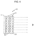
- the microlens unit 20 when positioned in front of the display unit 11 with the spacing nearly equal to its focal length, the microlens unit 20 visualizes the two-dimensional picture displayed on the display unit 11 on the imaginary image formation plate 25 as pseudo-stereoscopic picture. However, when positioned close to the display unit 11 as shown in FIG. 4, the microlens unit 20 simply passes the two-dimensional picture on the display unit 11 as it is.
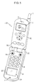
- FIG. 5 is a perspective view of the portable telephone 100 in an in-use state
- FIG. 6 is a perspective view of the potable telephone 100 in a call-waiting state
- FIG. 7 is a sectional view of the portable telephone 100 according to the line A-A in FIG. 6.
- the portable telephone 100 has a foldable structure in which a body unit 30 and a panel unit 31 are swingably connected to each other by a hinge portion 32.
- the antenna 1, the display unit 11, the speaker 5 and the plurality of operation buttons 33 including function keys are arranged on the body unit 30.
- the display unit 11 is a flat display such as a color LCD panel or an organic EL panel, and is attached to the body unit 30 such that the display surface is positioned at the same plane as the inner surface of the body unit 30 (facing the panel unit 31).
- the panel unit 31 is provided with the operation buttons 9 such as ten-keys on its inner face (confronting the body unit 30) and the microphone 4, and the microlens unit 20 is put in the opening window 34.
- the microlens unit 20 When the panel unit 31 is positioned at the foldedposition (first position) to cover the operation buttons 9 and 33 as shown in FIG. 7, the microlens unit 20 is located at the position remote from the display unit 11 by the focal length L. As described above with reference to FIG. 2, when positioned remotely from the display unit 11 by the focal length L, the microlens unit 20 forms the imaginary image formation plane 25 at the position remote from the surface of the microlens unit 20 by the focal length L, on the side opposite to the display unit 11. Therefore, in the folded state, i.e., in the call-waiting state, the portable telephone 100 can visualize the two-dimensional picture such as character picture displayed on the display unit 11 at the imaginary image formation plane 25 formed by the microlens unit 20 as the pseudo-stereoscopic picture.
- the microlens unit 20 is moved to the position at which the display unit 11 is not covered. Therefore, the display unit 11 of the portable telephone 100 is exposed to the user, and the user can directly read the information displayed on the display unit 11.
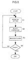
- FIG. 8 is a flowchart showing the telephone number registering operation, the program of which is stored in the ROM 8 in advance as the telephone number registering program.
- the portable telephone 100 stores stereoscopic (three-dimensional) character pictures (such as still pictures and animation pictures) in the RAM 7.
- the controller 6 of the portable telephone 100 automatically executes the telephone number registering program shown in FIG. 8.
- the controller 6 performs telephone number setting control in step S1. Specifically, the controller 6 reads out the character information "NAME?" stored in the ROM 8, and displays "NAME?" on the display unit 11.
- the controller 6 displays "PHONE No.?" on the display unit 11.
- the controller 6 goes to step S2 to select character.
- Step S2 the controller 6 displays "CHARACTER?" and a plurality of character names to be selected on the display unit 11.
- the controller 6 goes to step S3.
- step S3 the controller 6 registers the "NAME", "PHONE No.” and the selected character name into the RAM 7 in the linked manner. Then, the controller 6 determines whether or not the user made the operation to finish the telephone number registering operation in step S4. If step S4 results in NO, the controller 6 returns to step S1 to repeat the above described steps. On the other hand, if step S4 results in YES, the controller 6 finishes the telephone number registering program.
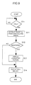
- FIG. 9 shows the flowchart of the character display operation, the program of which is stored in the ROM 8 in advance as the character display operation program.
- the portable telephone 100 receives the radio wave captured by the antenna 1 via the transceiver unit 2, and amplifies and demodulates the radio wave.
- the audio signal is amplified by the low-frequency amplifier 3 and outputted by the speaker 5.
- the character data such as the telephone number of the caller and/or the message are supplied to the controller 6.
- the transceiver unit 2 has a signal detection circuit (not shown) which outputs a DC voltage when it receives the radio wave.
- the controller 6 displays the signal intensity on the display unit 11 and determines whether or not the portable telephone 100 is in the radio wave receiving state, by using the output signal of the signal detection circuit.
- the controller 6 performs the operation control according to the flowchart shown in FIG. 9.
- the controller 6 detects the call-receiving state in step S10.
- the controller 6 goes to step S11.
- step S11 the controller 6 extracts the character information such as the caller' s telephone numbers and the messages from the demodulated signals and stores them into the RAM 7, and then goes to step S12.
- step S12 the controller 6 determines whether or not the caller' s telephone number is registered in the RAM 7. If step S12 results in NO, the controller 6 generates call melody indicating a phone call from a sound source or the like (not shown), and then ends the character display operation program.
- step S12 determines that the caller's telephone number is registered in the RAM 7 (step S12;YES)
- the controller 6 goes to step S13.
- the controller 6 reads out the character picture data linked with the caller's telephone number thus detected, and controls the drive circuit 10 to display the character picture on the display unit 11. Then, the controller 6 generates the call melody indicating a phone call in step S14, and ends the character display operation program.
- the microlens unit 20 is positioned in front of the display unit 11 when the panel unit 31 is in the folded position (i.e., in the call-waiting state) shown in FIG. 6. Therefore, when the portable telephone 100 displays the character picture on the display unit 11 after receiving the call, the character picture is visualized by the microlens unit 20 as a pseudo-stereoscopic picture, thereby giving the user pleasure or enjoyable feeling at the time of phone call.
- the panel unit 31 when the panel unit 31 is in the first position (i.e., in-use position) as shown in FIG. 5, the panel unit 31 is opened so that the microlens unit 20 is moved to the position not to cover the display unit 11. Therefore, the display unit 11 of the potable telephone 100 is exposed to provide the user with the normal, two-dimensionalpicture.
- the display unit 11 of the portable telephone 100 displays the telephone number and the like, which are not needed and suitable to be displayed in the pseudo-stereoscopic manner, thereby avoiding the user's eyestrain.
- the character picture displayed at the time of phone-call is visualized as the pseudo-stereoscopic picture.
- the game picture may be displayed on the display unit 11 by the manipulation of the operation button 31 provided on the outer surface of the panel 31 so that the user can enjoy the game with seeing the game picture in the pseudo-stereoscopic manner in the state that the panel unit 31 is folded.
- FIG. 10 is a perspective view of the portable telephone 110 in the in-use state
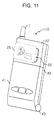
- FIG. 11 is a perspective view of the portable telephone 110 in the call-waiting state.
- the portable telephone 110 is configured by a body unit 40, a first panel unit 41 and a second panel unit 42.
- the antenna 1, the display unit 11, the speaker 5 and a plurality of function keys 44 are arranged on the body unit 40.
- the first panel unit 41 is connected to the lower end of the body unit 40 by the hinge portion 43 such that the first panel unit 41 can be opened and closed, and the operation buttons 9 such as ten-keys and the microphone 4 are arranged on the inner face of the first panel unit 41 confronting the body unit 40.
- the second panel unit 42 is connected to the upper end of the body unit 40 by a connecting portion (not shown) such that the second panel unit 42 can be opened and closed.
- the microlens unit 20 is attached in the opening window 42a.
- the portable telephone 110 according to the second embodiment differs from the portable telephone 100 according to the first embodiment in that only the microlens unit 20 is attached to the body unit 40 in such a manner that it can be arbitrarily opened and closed, and other portions are configured in the same manner as those of the portable telephone 100 according to the first embodiment.
- the portable telephone 110 when the panel units 41 and 42 are in the folded, second position (call-waiting state) as shown in FIG. 11, the microlens unit 20 is positioned to confront the front face of the display unit 11. By this, the portable telephone 110 visualizes the character picture at the time of phone call as apseudo-stereoscopic picture, thereby giving the user pleasure or enjoyable feeling at the time of phone call. Further, according to the portable telephone 110, since only the second panel unit 42 having the microlens unit 20 may be opened and closed, the user can, if desired, open only the second panel unit 42 to see the normal two-dimensional picture displayed on the display unit 11.
- the microlens unit 20 is moved to the position not to over the display unit 11. Therefore, the portable telephone 110 exposes the display unit 11, and provides the normal two-dimensional picture which is easy to see by the user.
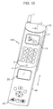
- FIG. 12 is a perspective view of the portable telephone 120 in the in-use state
- FIG. 13 is a perspective view of the portable telephone 120 in the call-waiting state.
- the portable telephone 120 is configured by the body unit 45 and the panel unit 46, and the panel unit 46 is attached to the body unit 45 in a manner slidable in the direction of the arrow in FIG. 12.
- the antenna 1, the display unit 11, the speaker 5, the operation buttons 9 and the microphone 4 are arranged on the body unit 45, and the microlens unit 20 and a plurality of function buttons 48 are arranged on the panel unit 46.
- the portable telephone 120 according to the third embodiment differs from the portable telephones according to the first and second embodiment in that the panel unit 46 is attached to the body unit 45 in the slidable manner, and other portions are configured in the same manner.
- the portable telephone 120 when the slidable panel units 46 is in the closed, second position (call-waiting state) as shown in FIG. 13, the microlens unit 20 is positioned to confront the front face of the display unit 11. By this, the portable telephone 120 visualizes the character picture at the time of phone call as a pseudo-stereoscopic picture, thereby giving the user pleasure or enjoyable feeling at the time of phone call.
- the microlens unit 20 is moved to the position not to cover the display unit 11. Therefore, the portable telephone 120 exposes the display unit 11, and provides the normal two-dimensional picture which is easy to see by the user.
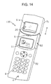
- FIG. 14 is a perspective view of the portable telephone 130 in the in-use state
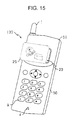
- FIG. 15 is a perspective view of the portable telephone 130 in the call-waiting state.
- the portable telephone 130 is configured by the body unit 50 and the panel unit 51, and the panel unit 51 is attached to the body unit 50 in a manner slidable along the groove 52 in the direction of the arrow in FIG. 14.
- the antenna 1, the display unit 11, the speaker 5, the operation buttons 9 and the microphone 4 are arranged on the body unit 50, and the microlens unit 20 is attached to the opening window 51a of the panel unit 51.
- the portable telephone 130 according to the fourth embodiment differs from the portable telephone 120 according to the third embodiment in that the panel unit 51 has only the microlens unit 20, and other portions are configured in the same manner.
- the portable telephone 130 when the panel units 51 is in the closed, second position (call-waiting state) as shown in FIG. 15, the microlens unit 20 is positioned to confront the front face of the display unit 11. By this, the portable telephone 130 visualizes the character picture at the time of phone call as a pseudo-stereoscopic picture, thereby giving the user pleasure or enjoyable feeling at the time of phone call. Further, according to the portable telephone 130, the user can, if desired, slide the panel 51 to see the normal two-dimensional picture displayed on the display unit 11.
- the microlens unit 20 is moved to the position not to over the display unit 11. Therefore, the portable telephone 130 exposes the display unit 11, and provides the normal two-dimensional picture.
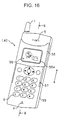
- FIG. 16 is a perspective view of the portable telephone 140 in the in-use state
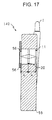
- FIG. 17 is a sectional view of the portable telephone 140 at the B-B line in FIG. 16
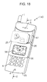
- FIG. 18 is a perspective view of the portable telephone 140 in the call-waiting state
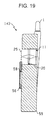
- FIG. 19 is a sectional view of the portable telephone 140 at the C-C line in FIG. 18.
- the portable telephone 140 is configured by the body unit 55 and the panel unit 56.
- the panel unit 56 is attached to the body unit 55 in a manner slidable along the groove 57 in the direction of the arrow in FIG. 16.
- the antenna 1, the display unit 11, the speaker 5, the operation buttons 9, the microphone 4 and the microlens unit 20 are arranged on the body unit 55, and the screen 58 made of transparent acrylic plate is attached in the opening window 56a of the panel unit 56.
- the microlens unit 20 is at the position remote from the display unit 11 by the focal length L of the microlens unit 20.
- the panel unit 56 is at the upper position where it does not cover the operation buttons 9 on the body unit 55, the screen 58 is at the position remote from the microlens unit 20 by the focal length L.
- the portable telephone 140 when the slidable panel unit 56 is in the pulled-down, second position (call-waiting state) as shown in FIGS. 18 and 19, the portable telephone 140 visualizes the character picture at the time of phone call as a pseudo-stereoscopic picture at the imaginary image formation plane 25, thereby giving the user pleasure or enjoyable feeling at the time of phone call.
- the portable telephone 140 projects the picture on the display unit 11 on the screen 58, and provides the normal two-dimensional picture in a manner easy to see by the user.
- FIG. 20 is a magnified sectional view of a portion of the portable telephone 150 in the call-waiting state
- FIG. 21 is a magnified sectional view of a part of the portable telephone 150 in the in-use state.
- the portable telephone 150 has the appearance generally identical to that of the portable telephone 140 according to the fifth embodiment shown in FIG. 16.
- the portable telephone 150 according to the sixth embodiment differs from the portable telephone 140 according to the fifth embodiment in that the screen 58 is not attached to the opening window 56a of the panel unit 56 and that the sliding plate 62 connected to the panel unit 56 moves the microlens unit 20 vertically upward and downward with respect to the display unit 11.
- the pins 20a protruding from both sides of the microlens unit 20 are inserted into the oblique guide grooves 62a of the sliding plate 62 and the vertical guide slot of the guide plate (not shown).
- the guide grooves 62a of the sliding plate 62 are formed in a manner obliquely extending downward and leftward direction in FIGS. 20 and 21, and the leftward-rightward movement of the sliding plate 62 moves the microlens unit 20 vertically upward and downward with respect to the display unit 11.
- the portable telephone 150 when the panel unit 56 is at the first position (call-waitingposition) covering a part of the operation unit of the body unit as shown in FIG. 20, the microlens unit 20 is located at the position remote from the display unit 11 by the focal length by means of the sliding plate 62 (i.e., first position), and the portable telephone 140 visualizes the character picture at the time of phone call as a pseudo-stereoscopic picture at the imaginary image formation plane 25, thereby giving the user pleasure or enjoyable feeling at the time of phone call.
- the microlens unit 20 moves to and closely contacts the display unit 11 by the cooperation with the sliding plate 62. Therefore, the microlens unit 20 passes the picture on the display unit 11 to provide the normal two-dimensional picture in a manner easy to see by the user.
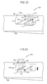
- FIG. 22 is a magnified sectional view of a part of the portable telephone 160 in the call-waiting state
- FIG. 23 is a magnified sectional view of a part of the portable telephone 160 in the in-use state.
- the portable telephone 160 according to the seventh embodiment differs from the portable telephone 150 according to the sixth embodiment in that the screen 63 is provided to the body unit 60 to cover the front face of the microlens unit 20. By this, the microlens unit 20 is protected from possible scratch or dust.
- the microlens unit 20 when the panel unit 56 is at the first position (call-waiting position) covering a part of the operation unit of the body unit as shown in FIG. 22, the microlens unit 20 is located at the position remote from the display unit 11 by the focal length by means of the sliding plate 62 (i.e., first position), and visualizes the character picture at the time of phone call as a pseudo-stereoscopic picture at the imaginary image formation plane 25, thereby giving the user pleasure or enjoyable feeling at the time of phone call.
- the microlens unit 20 moves to and closely contacts the display unit 11 by the cooperation with the movement of the sliding plate 62 in the right direction in FIG. 23. Therefore, the portable telephone 160 passes the two-dimensional picture on the display unit 11 through the microlens unit 20 and the screen 63 to provide the normal two-dimensional picture in a manner easy to see by the user.
- FIG. 24 is a magnified sectional view of a part of the portable telephone 170 in the call-waiting state
- FIG. 25 is a magnified sectional view of a part of the portable telephone 170 in the in-use state.
- the portable telephone 170 according to the eighth embodiment differs from the portable telephone 160 according to the seventh embodiment in that the movable range of the microlens unit 20 by the sliding plate 62 is changed. Namely, according to the portable telephone 160 of the seventh embodiment, the microlens unit 20 is moved between the position remote from the display unit 11 by the focal length (see. FIG.22) and the position in close contact with the display unit 11 (see. FIG. 23). In contrast, according to the portable telephone 170 according to the eighth embodiment, the microlens unit 20 is moved between the position remote from the display unit 11 by the focal length (see. FIG. 24) and the position at the middle of the screen 63 and the display unit 11 (see. FIG. 25).
- the microlens unit 20 when the panel unit 56 is at the first position (call-waiting position) covering a part of the operation unit of the body unit as shown in FIG. 24, the microlens unit 20 is located at the position remote from the display unit 11 by the focal length by means of the sliding plate 62 (i.e., first position), and visualizes the character picture displayed on the display unit 11 at the time of phone call as a pseudo-stereoscopic picture at the imaginary image formation plane 25 over the screen 63, thereby giving the user pleasure or enjoyable feeling at the time of phone call.
- the microlens unit 20 moves down to position at the middle of the screen 63 and the display unit 11 by the cooperation with the movement of the sliding plate 62 in the right direction in FIG. 25 (this is second position) . Therefore, the portable telephone 170 projects the two-dimensional picture on the display unit 11 by the microlens unit 20 onto the screen 63 to provide the normal two-dimensional picture in a manner easy to see by the user.
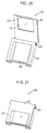
- FIG. 26 is a perspective view of the lens adapter 80 when the panel unit 82 is opened
- FIG. 27 is a perspective view of the lens adapter 80 when the panel unit 82 is closed
- FIG. 28 is a perspective view of the portable telephone 180 to which the lens adapter 80 can be attached
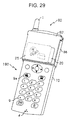
- FIG. 29 is a perspective view of the portable telephone 180 when the lens adapter 80 is attached and the panel unit 82 is closed
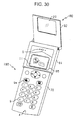
- FIG. 30 is a perspective view of the portable telephone 180 when the lens adapter 80 is attached and the panel unit 82 is opened.
- the lens adapter 80 includes the attachment unit 84 and the panel unit 82. Both sides of the attachment unit 84 are folded so that it may be attached to a general-use portable telephone 180 as shown in FIGS. 29 and 30.
- the attachment unit 84 has an opening window 85 by which the display unit 11 and the speaker 5 of the portable telephone 180 are exposed.
- the panel unit 82 has an opening window 82a to which the microlens unit 20 is attached.
- the panel unit 82 is attached to the attachment unit 84 by the hinge portion 83 such that the panel unit 82 can be opened and closed.
- FIG. 28 illustrates the appearance of the portable telephone 180 to which the lens adapter 80 of this embodiment can be attached.
- the portable telephone 180 has the antenna 1, the speaker 5, the display unit 11, the operation buttons 9 including the talk button 9a, and the microphone 4.
- the lens adapter 80 is attached to the portable telephone 180 from upper portion thereof.
- the lens adapter 80 When the panel unit 82 is at the closed, first position (i.e., call waiting position) as shown in FIG. 29, the lens adapter 80 is located at the position remote from the display unit 11 by the focal length in parallel with the front face of the display unit 11, and thereby visualizes the character picture displayed on the display unit 11 at the imaginary image formation plane 25 as the pseudo-stereoscopic picture to give the user pleasure or enjoyable feeling at the time of the phone call.
- the lens adapter 80 exposes the display unit 11 and the speaker 5 of the portable telephone 180 by the opening window 85, thereby providing normal two-dimensional picture to the user.
- the microlens unit 20 is attached to the panel unit 82 which can be opened and closed.
- the microlens unit 20 may be attached into the opening window 85 of the attachment unit 84 so that the user can attach the lens adapter 80 to the portable telephone 180 only when he or she wants to see and enjoy the pseudo-stereoscopic picture.
- the application of the present invention is not limited to the features described in the above embodiments.
- the above embodiments are directed to the application of the present invention to the portable telephone, the present invention may also be applied to a codeless telephone, a PHS telephone, a car telephone and other various communication terminal devices.
- the microlens unit 20 may be fixed to the call-waiting position and the display unit 11 may be vertically moved by the movement of the sliding plate 62.
- the two-dimensional picture displayed on the display unit may be visualized as the pseudo-stereoscopic picture, and hence the user may have pleasure or enjoyable feeling.
Landscapes
- Physics & Mathematics (AREA)
- Engineering & Computer Science (AREA)
- Signal Processing (AREA)
- General Physics & Mathematics (AREA)
- Optics & Photonics (AREA)
- Multimedia (AREA)
- Telephone Set Structure (AREA)
Abstract
Description
Claims (12)
- A communication terminal device (100, 110, 120, 130) comprising:a display unit (11) for displaying two-dimensional picture;a microlens unit (20) including a pair of microlens arrays (21) ;a panel unit (31, 42, 46, 51) for supporting the microlens unit and being movable between a first position at which the microlens unit confronts the display unit with a spacing substantially equal to a focal length of (L) the microlens unit and a second position at which the microlens unit does not confront the display unit.
- A communication terminal device (100, 110, 120) according to claim 1, wherein the panel unit covers at least a part of an operation unit (9) provided on the communication terminal device when the panel unit is at the first position.
- A communication terminal device (100, 110) according to claim 2, wherein the panel unit is supported by the communication terminal device in such a manner that the panel unit can be opened and closed, and at least one of an operation unit (9) and a microphone (4) is arranged on an inner face of the communication terminal device.
- A communication terminal device (140) comprising:a display unit (11) for displaying two-dimensional picture;a microlensunit (20) including apair of microlens arrays (21) and positioned to confront the display unit;a screen (58); anda panel unit (56) for supporting the screen and being movable between a first position at which the screen confronts a face of the microlens unit at the opposite side of the display unit and a second position at which the screen does not confront the display unit.
- A communication terminal device (140) according to claim 4, wherein the panel unit covers at least a part of an operation unit (9) provided on the communication terminal device when the panel unit is at the second position.
- A communication terminal device (150) comprising:a display unit (11) for displaying two-dimensional picture;a microlensunit (20) including a pair of microlens arrays (21) and positioned to confront the display unit;a drive unit (62) for moving the microlens unit with respect to the display unit to establish a first state in which the microlens unit and the display unit are remote from each other by a focal length (L) of the microlens unit and a second state in which microlens unit and the display unit are in close contact with each other.
- A communication terminal device (150, 160) according to claim 6, further comprising a panel unit (56) movable between a first position at which the panel unit covers at least a part of an operation unit (9) provided on the communication terminal device and a second position at which the panel unit does not cover the operation unit, wherein the drive unit moves the microlens unit with respect to the display unit to change the microlens unit and the display unit from the first state to the second state according to a movement of the panel unit from the first position to the second position.
- A communication terminal device (160) according to claim 6, further comprising a screen (63) positioned in front of a face, opposite to the display unit, of the microlens unit in the first state with a spacing smaller than the focal length.
- A communication terminal device (170) comprising:a display unit (11) for displaying two-dimensional picture;a microlens unit (20) includingapairofmicrolensarrays (21);a screen (63) positioned to confront a face of the microlens unit at the opposite side of the display unit; anda drive unit (62) for moving the microlens unit with respect to the display unit to establish a first state, in which the microlens unit is remote from the display unit by a focal length (L) of the microlens unit and an image forming plane of the microlens unit is positioned over the screen in the first position, and a second state, in which the microlens unit is positioned at a middle of the display unit and the screen.
- A communication terminal device (170) according to claim 9, further comprising a panel unit (56) movable between a first position at which the panel unit covers at least a part of an operation unit provided on the communication terminal device and a second position at which the panel unit does not cover the operation unit, wherein the drive unit moves the microlens unit to be close to the display unit to change the microlens unit and the display unit from the first state to the second state according to a movement of the panel unit from the first position to the second position.
- A lens adapter (80) comprising:an attachment unit (84) for detachably attaching the lens adapter to a communication terminal device (180) having a display unit (11) for displaying two-dimensional picture; anda microlensunit (20) including a pair of microlens arrays (21) and positioned to confront the display unit with a spacing substantially equal to a focal length (L) of the microlens unit when the lens adapter is attached to the communication terminal device.
- A lens adapter (80) according to claim 11, further comprising a panel unit (82) for supporting the microlens unit (20) and being movable between a first position at which the microlens unit confronts the display unit and a second position at which the microlens unit does not confront the display unit.
Applications Claiming Priority (2)
| Application Number | Priority Date | Filing Date | Title |
|---|---|---|---|
| JP2000265729 | 2000-09-01 | ||
| JP2000265729A JP4049977B2 (en) | 2000-09-01 | 2000-09-01 | Communication terminal device and lens adapter used for communication terminal device |
Publications (2)
| Publication Number | Publication Date |
|---|---|
| EP1184704A2 true EP1184704A2 (en) | 2002-03-06 |
| EP1184704A3 EP1184704A3 (en) | 2002-07-03 |
Family
ID=18752955
Family Applications (1)
| Application Number | Title | Priority Date | Filing Date |
|---|---|---|---|
| EP01307421A Ceased EP1184704A3 (en) | 2000-09-01 | 2001-08-31 | Communication terminal device and lens adaptor |
Country Status (3)
| Country | Link |
|---|---|
| US (1) | US7012745B2 (en) |
| EP (1) | EP1184704A3 (en) |
| JP (1) | JP4049977B2 (en) |
Cited By (2)
| Publication number | Priority date | Publication date | Assignee | Title |
|---|---|---|---|---|
| EP1531632A3 (en) * | 2003-11-12 | 2008-02-13 | Pioneer Corporation | Stereoscopic two-dimensional image display system and image display method |
| CN104025461A (en) * | 2011-12-28 | 2014-09-03 | Lg电子株式会社 | Mobile terminal |
Families Citing this family (34)
| Publication number | Priority date | Publication date | Assignee | Title |
|---|---|---|---|---|
| US7466992B1 (en) * | 2001-10-18 | 2008-12-16 | Iwao Fujisaki | Communication device |
| JP2003204383A (en) * | 2001-10-26 | 2003-07-18 | Nec Corp | Portable telephone |
| US7034833B2 (en) * | 2002-05-29 | 2006-04-25 | Intel Corporation | Animated photographs |
| JP2004007188A (en) * | 2002-05-31 | 2004-01-08 | Toshiba Corp | Electronics |
| AU2003252388A1 (en) * | 2002-08-27 | 2004-03-19 | Sharp Kabushiki Kaisha | Content reproduction device capable of reproducing a content in optimal reproduction mode |
| JP2004128909A (en) * | 2002-10-03 | 2004-04-22 | Hitachi Ltd | Mobile terminal |
| JP2004135177A (en) | 2002-10-11 | 2004-04-30 | Sharp Corp | Mobile phone |
| US7372629B2 (en) * | 2003-11-06 | 2008-05-13 | Nec Corporation | Three-dimensional image display device, portable terminal device, display panel and fly eye lens |
| JP2005141102A (en) * | 2003-11-07 | 2005-06-02 | Pioneer Electronic Corp | Stereoscopic two-dimensional image display device and its method |
| JP4497905B2 (en) * | 2003-12-08 | 2010-07-07 | パイオニア株式会社 | Image display device |
| JP4411059B2 (en) * | 2003-12-12 | 2010-02-10 | キヤノン株式会社 | Display device with camera, communication device, and communication system |
| JP4482556B2 (en) * | 2004-03-31 | 2010-06-16 | パイオニア株式会社 | Stereoscopic two-dimensional image display device |
| WO2006035816A1 (en) | 2004-09-30 | 2006-04-06 | Pioneer Corporation | Pseudo-3d two-dimensional image display device |
| US8094184B2 (en) | 2004-10-07 | 2012-01-10 | Pioneer Corporation | Stereoscopic two-dimensional display device |
| JP2006343501A (en) * | 2005-06-08 | 2006-12-21 | Pioneer Electronic Corp | Image display device |
| TWI281811B (en) * | 2005-07-01 | 2007-05-21 | Wintek Corp | Mobile communication device |
| CN1767561B (en) * | 2005-11-09 | 2010-11-17 | 阮立山 | Method for carrying out opening or amplification for font on handset screen |
| WO2008041313A1 (en) * | 2006-10-02 | 2008-04-10 | Pioneer Corporation | Image display device |
| US20080090564A1 (en) * | 2006-10-15 | 2008-04-17 | Hamid Najafi | Wireless phone module and method |
| TWI339328B (en) * | 2007-10-17 | 2011-03-21 | Inventec Corp | Slide type portable electronic device |
| US20090180166A1 (en) * | 2008-01-16 | 2009-07-16 | Samsung Electronics Co., Ltd. | Imaging using diffraction optics elements |
| US20090180180A1 (en) * | 2008-01-16 | 2009-07-16 | Samsung Electronics Co., Ltd. | Sub-pixel optical array |
| US9152309B1 (en) * | 2008-03-28 | 2015-10-06 | Google Inc. | Touch screen locking and unlocking |
| US8908015B2 (en) | 2010-03-24 | 2014-12-09 | Appcessories Llc | Apparatus and method for producing images for stereoscopic viewing |
| JP2013190448A (en) * | 2010-06-30 | 2013-09-26 | Sharp Corp | Display device |
| USD671158S1 (en) | 2010-09-24 | 2012-11-20 | Hasbro, Inc. | Viewer apparatus |
| WO2012070139A1 (en) * | 2010-11-25 | 2012-05-31 | 株式会社ライツ | Three-dimensional video display device |
| JP5341162B2 (en) * | 2011-10-27 | 2013-11-13 | 株式会社ライツ | 3D image display device |
| WO2012070553A1 (en) * | 2010-11-25 | 2012-05-31 | 株式会社ライツ | Three-dimensional video display device |
| JP2013160793A (en) * | 2012-02-01 | 2013-08-19 | Bruck Private Ltd | Three-dimensional picture display device |
| JP2012137766A (en) * | 2012-02-06 | 2012-07-19 | Raitsu:Kk | Three-dimensional image display device |
| US8504842B1 (en) | 2012-03-23 | 2013-08-06 | Google Inc. | Alternative unlocking patterns |
| FR3092674A1 (en) * | 2019-02-07 | 2020-08-14 | Oberthur Fiduciaire Sas | TOGETHER CONSTITUTES A TWO-DIMENSIONAL NETWORK OF MICRO-OPTICAL DEVICES AND A NETWORK OF MICRO-IMAGES, METHOD FOR ITS MANUFACTURING, AND SECURITY DOCUMENT CONTAINING IT |
| KR20240085348A (en) * | 2022-12-07 | 2024-06-17 | 삼성디스플레이 주식회사 | Display device |
Family Cites Families (8)
| Publication number | Priority date | Publication date | Assignee | Title |
|---|---|---|---|---|
| JPS552449Y2 (en) | 1973-07-11 | 1980-01-22 | ||
| JP3461828B2 (en) * | 1993-03-25 | 2003-10-27 | デ モントフォート ユニヴァーシティ | Lens device |
| US5500765A (en) * | 1994-05-11 | 1996-03-19 | Dimension Technologies Inc. | Convertible 2D/3D autostereoscopic display |
| US5763079A (en) | 1995-05-23 | 1998-06-09 | Atlantic Research Corporation | Wire preforms for composite material manufacture and methods of making |
| US5970418A (en) * | 1995-09-21 | 1999-10-19 | International Business Machines Corporation | Personal communicator including a handset phone with an integrated virtual image display |
| GB2307058A (en) | 1995-11-13 | 1997-05-14 | Thomson Multimedia Sa | Stereoscopic display with lens,prism and barrier arrays |
| JP3647118B2 (en) | 1996-01-23 | 2005-05-11 | キヤノン株式会社 | Stereoscopic image display device |
| US6389268B1 (en) * | 1999-07-29 | 2002-05-14 | Ericsson Inc. | Electronic device holders with display panel magnifier |
-
2000
- 2000-09-01 JP JP2000265729A patent/JP4049977B2/en not_active Expired - Fee Related
-
2001
- 2001-08-29 US US09/941,163 patent/US7012745B2/en not_active Expired - Fee Related
- 2001-08-31 EP EP01307421A patent/EP1184704A3/en not_active Ceased
Cited By (3)
| Publication number | Priority date | Publication date | Assignee | Title |
|---|---|---|---|---|
| EP1531632A3 (en) * | 2003-11-12 | 2008-02-13 | Pioneer Corporation | Stereoscopic two-dimensional image display system and image display method |
| CN104025461A (en) * | 2011-12-28 | 2014-09-03 | Lg电子株式会社 | Mobile terminal |
| CN104025461B (en) * | 2011-12-28 | 2016-02-24 | Lg电子株式会社 | Mobile terminal |
Also Published As
| Publication number | Publication date |
|---|---|
| JP4049977B2 (en) | 2008-02-20 |
| US7012745B2 (en) | 2006-03-14 |
| JP2002077341A (en) | 2002-03-15 |
| EP1184704A3 (en) | 2002-07-03 |
| US20020032043A1 (en) | 2002-03-14 |
Similar Documents
| Publication | Publication Date | Title |
|---|---|---|
| US7012745B2 (en) | Communication terminal device and lens adapter | |
| JP2002290793A (en) | Mobile phone with imaging device | |
| KR100608727B1 (en) | Separate mobile terminal for video call and communication method thereof | |
| EP1387582B1 (en) | Portable device displaying an image provided by photographing | |
| US8457690B2 (en) | Multi-housing mobile terminal | |
| CN1308810B (en) | TV Telephone System Using Portable Communication Terminal | |
| CN101129053A (en) | portable information terminal | |
| JP4147016B2 (en) | Mobile device | |
| JP2006527928A5 (en) | ||
| KR100636452B1 (en) | Portable terminal and announcement method thereof | |
| JP4071727B2 (en) | mobile phone | |
| JP2003022066A (en) | Communication terminal device and method for displaying space character | |
| JP2005182367A (en) | Mobile terminal device | |
| JPH09247250A (en) | Wireless device | |
| JP4093832B2 (en) | Portable device | |
| EP1903756A2 (en) | Mobile communication terminal for MP3 | |
| JP4393750B2 (en) | Openable mobile terminal device | |
| JP2002218030A (en) | Folding portable terminal | |
| JP2007096991A (en) | Broadcast receiver | |
| JP2004056297A (en) | Portable terminal device | |
| JP2012100135A (en) | Portable communication terminal and computer software of the same | |
| KR100383443B1 (en) | A mobile telecommunication terminal having a magnifying glass | |
| KR200308286Y1 (en) | Lcd display enlargement apparatus for portable terminal | |
| JP2008085705A (en) | Portable electronic devices | |
| KR200376789Y1 (en) | Mobile terminal having a slider moving upward and downward |
Legal Events
| Date | Code | Title | Description |
|---|---|---|---|
| PUAI | Public reference made under article 153(3) epc to a published international application that has entered the european phase |
Free format text: ORIGINAL CODE: 0009012 |
|
| AK | Designated contracting states |
Kind code of ref document: A2 Designated state(s): AT BE CH CY DE DK ES FI FR GB GR IE IT LI LU MC NL PT SE TR |
|
| AX | Request for extension of the european patent |
Free format text: AL;LT;LV;MK;RO;SI |
|
| PUAL | Search report despatched |
Free format text: ORIGINAL CODE: 0009013 |
|
| AK | Designated contracting states |
Kind code of ref document: A3 Designated state(s): AT BE CH CY DE DK ES FI FR GB GR IE IT LI LU MC NL PT SE TR |
|
| AX | Request for extension of the european patent |
Free format text: AL;LT;LV;MK;RO;SI |
|
| RIC1 | Information provided on ipc code assigned before grant |
Free format text: 7G 02B 25/00 A, 7H 04M 1/02 B, 7G 02B 27/22 B |
|
| 17P | Request for examination filed |
Effective date: 20021212 |
|
| 17Q | First examination report despatched |
Effective date: 20030121 |
|
| AKX | Designation fees paid |
Designated state(s): DE FR GB |
|
| STAA | Information on the status of an ep patent application or granted ep patent |
Free format text: STATUS: THE APPLICATION HAS BEEN REFUSED |
|
| 18R | Application refused |
Effective date: 20041223 |