EP1184655A2 - Stroke discriminator for an internal combustion engine - Google Patents
Stroke discriminator for an internal combustion engine Download PDFInfo
- Publication number
- EP1184655A2 EP1184655A2 EP01118361A EP01118361A EP1184655A2 EP 1184655 A2 EP1184655 A2 EP 1184655A2 EP 01118361 A EP01118361 A EP 01118361A EP 01118361 A EP01118361 A EP 01118361A EP 1184655 A2 EP1184655 A2 EP 1184655A2
- Authority
- EP
- European Patent Office
- Prior art keywords
- time
- detected
- internal combustion
- combustion engine
- value
- Prior art date
- Legal status (The legal status is an assumption and is not a legal conclusion. Google has not performed a legal analysis and makes no representation as to the accuracy of the status listed.)
- Granted
Links
Images





Classifications
-
- F—MECHANICAL ENGINEERING; LIGHTING; HEATING; WEAPONS; BLASTING
- F02—COMBUSTION ENGINES; HOT-GAS OR COMBUSTION-PRODUCT ENGINE PLANTS
- F02D—CONTROLLING COMBUSTION ENGINES
- F02D41/00—Electrical control of supply of combustible mixture or its constituents
- F02D41/009—Electrical control of supply of combustible mixture or its constituents using means for generating position or synchronisation signals
-
- G—PHYSICS
- G01—MEASURING; TESTING
- G01M—TESTING STATIC OR DYNAMIC BALANCE OF MACHINES OR STRUCTURES; TESTING OF STRUCTURES OR APPARATUS, NOT OTHERWISE PROVIDED FOR
- G01M15/00—Testing of engines
- G01M15/04—Testing internal-combustion engines
- G01M15/042—Testing internal-combustion engines by monitoring a single specific parameter not covered by groups G01M15/06 - G01M15/12
- G01M15/046—Testing internal-combustion engines by monitoring a single specific parameter not covered by groups G01M15/06 - G01M15/12 by monitoring revolutions
-
- F—MECHANICAL ENGINEERING; LIGHTING; HEATING; WEAPONS; BLASTING
- F02—COMBUSTION ENGINES; HOT-GAS OR COMBUSTION-PRODUCT ENGINE PLANTS
- F02D—CONTROLLING COMBUSTION ENGINES
- F02D2200/00—Input parameters for engine control
- F02D2200/02—Input parameters for engine control the parameters being related to the engine
- F02D2200/10—Parameters related to the engine output, e.g. engine torque or engine speed
- F02D2200/1015—Engines misfires
Definitions
- the present invention relates to stroke discrimination of a single-cylinder internal combustion engine.
- An apparatus for discriminating the stroke of internal combustion engines is disclosed in Japanese Patent Kokai No. 61-89959.
- the apparatus discriminates engine strokes using two detection signals transmitted by two crank angle sensors, respectively, which are provided near the crankshaft.
- the present invention was developed in view of the aforementioned problems in the prior art. It is therefore an object of the present invention to provide an apparatus having a simple configuration for discriminating the stroke of an internal combustion engine to determine the stroke of the internal combustion engine.
- a stroke discriminator of an internal combustion engine comprises a rotor operatively associated with a crankshaft of a single cylinder internal combustion engine and provided with a plurality of detected elements thereon.
- the stroke discriminator also comprises detector means for transmitting a detection signal every time said detected elements pass nearby and discriminator means for determining a stroke of the internal combustion engine in accordance with a difference in time between a transmission of a previous detection signal and a transmission of a current detection signal.
- the stroke discriminator is characterized in that an outer periphery of said rotor has a detected-element region having said plurality of detected elements formed thereon at equal angle intervals in a direction of rotation and a region which does not have detected elements formed thereon.
- the stroke discriminator is also characterized in that said region without the elements has an angle interval greater than said equal angle interval, and said region without the elements is provided on said rotor so as to pass near said detector means when a piston of said internal combustion engine travels from the top dead center to the bottom dead center.
- a single cylinder internal combustion engine 10 receives a mixture of intake gas drawn from an intake pipe (not shown) and fuel injected from a fuel injection unit (not shown) into a combustion chamber 20. Then, the internal combustion engine 10 allows the introduced gas mixture to be burned and thereby reciprocate a piston 12 for rotatably driving a crankshaft 14. The burned gas mixture in the combustion chamber 20 is exhausted as an exhaust gas through an exhaust pipe (not shown).
- the crankshaft 14 is provided with a rotor 50. As described later, on the periphery of the rotor 50, there is provided a plurality of elements for detection, i.e., a plurality of magnetic projections (not shown).
- a crank angle sensor 16 is located near the rotational locus of the magnetic projections. At predetermined crank angles, for example, at every 20 degrees of the crank angle, the crank angle sensor 16 transmits a detection signal indicative of the detection of a magnetic projection in response to a change in magnetic flux created by the magnetic projections.
- the detection signal transmitted from the crank angle sensor 16 is supplied to a waveform shaping circuit 32 of an electronic control unit (hereinafter referred to as the ECU), which shapes the detection signal into a pulse signal of pulse trains.
- the output terminal of the waveform shaping circuit 32 is connected to an interrupt input terminal of a central processing unit (hereinafter referred to as the CPU), while the pulse signal transmitted from the waveform shaping circuit 32 is supplied to the CPU 34.
- the CPU 34 executes an interrupt processing every time the CPU detects a pulse.
- the CPU 34 can execute a predetermined processing at each predetermined angle of the crankshaft.
- the CPU 34 is connected with an input/output bus 36, which is adapted to receive from and output to the CPU 34 a data signal or an address signal.
- the input/output bus 36 is connected with a ROM (Read Only memory) 38, a RAM (Random Access Memory) 40, and a drive circuit 42.
- the drive circuit 42 is connected to an ignition plug 18. Transmitting an ignition command from the CPU 34 to the drive circuit 42 causes the drive circuit 42 to supply a drive current to the ignition or spark plug 18. Supplying a drive current to the spark plug 18 will cause the spark plug 18 to spark.
- the spark ignites the gas mixture introduced into the combustion chamber 20, and the combustion of the gas mixture initiates the expansion stroke of the internal combustion engine.
- the aforementioned ROM 38 stores a program for determining the stroke of the internal combustion engine in accordance with the flowcharts, described later, shown in Fig. 3, Fig. 7, and Fig. 9 through Fig. 11.
- the RAM 40 stores the variables of a program or the values of flags, to be described later.
- Fig. 2 shows the arrangement of a plurality of magnetic projections, which are formed on the outer periphery of the rotor 50.
- Fig. 2 shows the arrangement of the magnetic projections provided when the piston 12 of the internal combustion engine 10 has reached the top dead center position.
- the arrangement of the magnetic projections given when the piston 12 has reached the bottom dead center position can be obtained by being rotated by 180 degrees about the crankshaft 14.
- the disc-shaped rotor 50 is provided on the crankshaft 14 to be operatively associated with the rotational motion of the crankshaft 14. As shown by the arrow in the figure, a counterclockwise rotation of the crankshaft 14 will cause the rotor 50 to rotate in the counterclockwise direction.
- On the outer periphery of the rotor 50 there is provided a plurality of detected elements, e.g., magnetic projections 52a-52o at predetermined equal angles, for example, at every 20 degrees.
- the neighboring magnetic projections 52a and 52o are at an angle of 80 degrees, which is greater than the aforementioned equal angle interval.
- the crank angle sensor 16 is located near the rotation locus of the magnetic projections 52a-52o. Every time the magnetic projections 52a-52o pass near the crank angle sensor 16, the crank angle sensor 16 transmits a detection signal indicative of the detection of a magnetic projection in response to a change in magnetic flux established by the magnetic projection.
- a detected-element formed region is the region where the magnetic projections are formed at equal angle interval, that is, the region of the outer periphery of the rotor 50 where the magnetic projections 52a-52o are formed, as indicated by an alternate long and short dashed line of Fig. 2.
- a non-formed region is the region where no magnetic projections are formed at an angle interval greater than the equal angle interval. This region is between the neighboring magnetic projections 52a and 52o, as indicated by a dashed line of Fig. 2.
- the magnetic projections 52a and 52o are provided on the rotor 50 so that the two magnetic projections 52a and 52o pass near the crank angle sensor 16 while the piston 12 of the internal combustion engine 10 is moving from the top dead center to the bottom dead center.
- the stroke of the internal combustion engine is either the expansion stroke or the intake stroke.
- the stroke of the internal combustion engine, during which all the non-formed regions pass near the crank angle sensor 16 is either the expansion stroke or the intake stroke.
- the piston 12 when the piston 12 has reached near the top dead center, the gas mixture introduced into the combustion chamber 20 of the internal combustion engine 10 is ignited.
- the piston 12 has maximum speed when the piston 12 is positioned near the middle point between the top dead center and bottom dead center while the piston 12 travels from the top dead center to the bottom dead center.
- the rotational speeds of the crankshaft and the rotor 50 operatively associated therewith move at maximum speed.
- the piston 12 is energized during the expansion stroke. This makes the speed at which the non-formed region passes near the crank angle sensor 16 in the expansion stroke greater than that at which the non-formed region passes near the crank angle sensor 16 in the intake stroke.
- the detector means comprise the aforementioned crank angle sensor 16, the determination means and the means for determining the expansion stroke comprise an ECU 30, and a plurality of detected elements comprise the magnetic projections 52a-52o.
- the ECU 30 has been activated and is in steady operation after having completed activation processing such as initialization of variables to be used in the CPU 34. It is also assumed that the timer, to be described later, is activated at the same time as the start-up of the internal combustion engine.
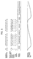
- Fig. 3 is a time chart showing the elapse times TM1 and TM2, while Fig. 5 illustrates the pulse signal supplied from the waveform shaping circuit 32 to the CPU 34, and the symbols of magnetic projections each corresponding to the respective pulses are shown near each pulse. Furthermore, the stage number to be defined by executing the routine of Fig. 3 is indicated near each corresponding pulse.
- the pre-started timer is stopped (step S11). Then, the timer is read to substitute the resulting timer value into the variable TM1 (step S12), and actuates the timer (step S13). The timer is started, stopped, and read at such timing. As shown in Fig. 4, the elapse time TM1 is thereby adapted to indicate the elapse time from the rising part of the previously detected pulse (hereinafter referred to as the previous pulse) to the rising part of the currently detected pulse (hereinafter referred to as the current pulse).
- the value of the elapse time TM1 is given when detected is the pulse P 1 transmitted for the first time after the internal combustion engine has been started.
- the elapse time TM1 is to indicate the elapse time from the point of time the timer has been activated by the start-up of the internal combustion engine to the time of detection of the pulse P 1 .
- the elapse time TM2 is to indicate the elapse time from the rising part of the second previously detected pulse (hereinafter referred to as a second previous pulse) to the rising part of the previous pulse.
- flag F_1stPC is one (step S14).
- This flag F_1stPC is indicative of whether the pulse P 1 transmitted for the first time since the internal combustion engine has been started is detected.
- the flag F_1stPC takes on a value of one when the first pulse P 1 has been detected, while the flag F_1stPC assumes a value of zero when the first pulse P 1 has not yet been detected.
- step S14 since the value zero of the flag F_1stPC remains unchanged, it is determined in step S14 that the flag F_1stPC does not have a value of one. Then, since the currently detected pulse P 1 is the first one, the flag F_1stPC is set to a value of one (step S15), and then this subroutine is terminated.
- step S14 since the first pulse P 1 has been detected, it is determined that the flag F_1stPC has a value of one and whether the flag F_2ndPC has a value of one (step S16). This flag F_2ndPC is indicative of whether the pulse P 2 transmitted for the second time since the internal combustion engine has been started is detected.
- the flag F_2ndPC takes on a value of one when the second pulse P 2 has been detected, while the flag F_2ndPC assumes a value of zero when the second pulse P 2 has not yet been detected. At this time, since the second pulse P 2 has just been detected and the flag F_2ndPC remains with the initial value, it is determined that the flag F_2ndPC does not have a value of one. Then, since the currently detected pulse is the second pulse P 2 , the flag F_2ndPC is set a value of one (step S17) and then the value of the elapse time TM1 is substituted into the elapse time TM2 (step S18), and thereafter this subroutine is terminated.
- step S18 mentioned above the value of the elapse time TM1 is substituted into the elapse time TM2.
- the elapse time TM1 thereby indicates the elapse time from the detection of the rising part of the previous pulse to the detection of the rising part of the current pulse when pulses subsequent to the pulse P 2 , shown in Fig. 5, are detected to execute this subroutine.
- the elapse time TM2 indicates the elapse time from the detection of the rising part of the second previous pulse to the detection of the rising part of the previous pulse.
- the flag F_1stPC and the flag F_2ndPC have a value of one.
- the processing from steps S11 through S14 is performed and thereafter the subroutine for determining a non-formed region, described later, is performed to determine whether the non-formed region has been detected (step S19).
- flag F_LONG_PC has a value of one (step S20).
- This flag F_LONG_PC is indicative of whether the non-formed region has been detected.
- the flag F_LONG_PC takes on a value of zero when the non-formed region has not previously been detected and a value of one when the non-formed region has previously been detected.
- the flag F_LONG_PC does not have a value of one, and then the variable STAGE is added by one (step S21). Since the value of the variable STAGE has been initialized, the variable STAGE takes on one at the time the pulse P 3 is detected.
- step S22 it is determined whether the variable STAGE has a value of less than 15 (step S22). As described above, since the variable STAGE has a value of one at the point of time the pulse P 3 is detected, it is determined that the variable STAGE has a value of less than 15 and then it is determined whether the flag F_360STG has a value of one (step S23).
- the flag F_360STG is indicative of whether the stage number has been identified. The flag F_360STG takes on a value of zero when the stage number has not yet been identified, while the flag F_360STG takes on a value of one when the stage number has been already identified. Since the stage number has not yet been identified at the point of time the pulse P 3 has been detected, it is determined that the flag F_360STG does not have a value of one, and then the processing of step S18 is performed to terminate this subroutine.
- the flag F_LONG_PC is set a value of one (step S47, described later) in the subroutine for determining a non-formed region of step S19.
- step S20 this allows it to be determined that the flag F_LONG_PC has a value of one and whether the flag F_1stLONG_PC has a value of one (step S24).
- the flag F_1stLONG_PC is indicative of whether the first non-formed region has been detected since the internal combustion engine 10 has been started.
- the flag has a value of zero when the first non-formed region has not yet been detected and value of one when the first non-formed region has already been detected.
- the flag F_1stLONG_PC has a value of zero. Then, the flag F_1stLONG_PC is set to a value of one (step S25), the variable STAGE is set to zero (step S26), the flag F_360STG is set to a value of zero (step S27), the processing of step S18 is performed, and then this subroutine is terminated.
- step S42 the flag F_LONG_PC is set again to a value of zero (step S42, described later) in the subroutine for determining a non-formed region of step S19.
- step S42 the flag F_LONG_PC does not have a value of one in step S20, and then the processing of the aforementioned steps S21 through S23 and S18 is performed.
- the stage number is increased by one every time the aforementioned processing of step S21 is performed.
- stage number is one upon detection of pulse P 6 , the stage number to be two upon detection of pulse P 7 , and the stage number to be three upon detection of pulse P 8 .
- the stage number is increased by one to cause the stage number to be 14 upon detection of pulse P 19 .
- step S20 it is determined that the flag F_LONG_PC has a value of one and whether the flag F_1stLONG_PC has a value of one (step S24).
- step S24 Since the flag F_1stLONG_PC is set to a value of one in the aforementioned step S25, it is determined in step S24 that the flag F_1stLONG_PC has a value of one and whether the variable STAGE has a value of 14 (step S28). As described above, since the stage number is 14 upon detection of the pulse, it is determined that the variable STAGE has a value of 14 in step S28, and then the flag F_360STG is set to a value of one (step S29). The processing of step S29 identifies the stage number.
- step S28 when it has been determined in the aforementioned step S28 that the variable STAGE does not have a value of 14, the processing proceeds to step S27 to set the flag F_360STG to a value of one.
- This processing is to prevent malfunctioning in detecting a pulse signal containing noise even when it has been accidentally determined by detecting the noise component that a magnetic projection has passed.
- step S30 the processing for determining an engine stroke, to be described later, is performed (step S30). Then, the variable STAGE is set to zero (step S31), and then it is determined whether the flag F_360STG has a value of one (step S23). Since the flag F_360STG is set to a value of one in the aforementioned step S29, it is determined that the flag F_360STG has a value of one and then it is determined whether the variable STAGE has a value of 10 (step S32). Since the variable STAGE is set to a value of zero in the aforementioned step S31, it is determined that the variable STAGE does not have a value of 10 and then the processing proceeds to step S18 to terminate this subroutine.
- step S32 Since the variable STAGE takes on a value of 10 in step S21 of this processing, it is determined in step S32 that the variable STAGE has a value of 10, the value of TM1 is substituted into a variable TM3 (step S33), the processing of step S18 is performed, and then this subroutine is terminated. Since the aforementioned step S33 is executed only when the variable STAGE has a value of 10, the variable TM3 indicates the elapse time from the detection of the rising part of a magnetic projection 52k to the detection of the rising part of the magnetic projection 521.
- step S22 it is determined whether the variable STAGE is greater than 15. This is performed to prevent malfunctioning in detecting a pulse signal containing noise even when it has been accidentally determined by detecting the noise component that a magnetic projection has passed.
- the variable is reset (step S34 through S39), and then the processing proceeds to step S18.
- pulses subsequent to the pulse P 31 are detected to execute this subroutine.
- executed is the processing of steps S11, S12, S13, S14, S16, S19, S20, S21, S22, S23, S32, S33, and S18, in that order.
- executed is the processing of steps S11, S12, S13, S14, S16, S19, S20, S21, S22, S23, S32, and S18, in that order.
- Figs. 6A through 6C are time charts illustrating the relationship between the aforementioned elapse times TM1 and TM2, and detected-element formed and non-formed regions.
- the non-formed region corresponding to a period between the previous pulse and the current pulse is the basis for the time chart as shown in Fig. 6A.
- the current pulse is transmitted upon detection of the magnetic projection 52a
- the previous pulse is transmitted upon detection of the magnetic projection 52o
- the second previous pulse is transmitted upon detection of the magnetic projection 52n. Since Fig. 6A shows the case where the non-formed region corresponds to between the previous pulse and the current pulse, the elapse time TM1 is greater than the elapse time TM2, and thus the ratio of the elapse time TM2 to the elapse time TM1 is less than one.
- Fig. 6B is a time chart illustrating an example in which the detected-element formed region corresponds to both a period between the second previous pulse and the previous pulse and between the previous pulse and the current pulse.
- the current pulse is transmitted upon detection of the magnetic projection 52h
- the previous pulse is transmitted upon detection of the magnetic projection 52g
- the second previous pulse is transmitted upon detection of the magnetic projection 52f.
- the elapse time TM1 is generally equal to the elapse time TM2, and thus the ratio of the elapse time TM2 to the elapse time TM1 is approximately one.
- Fig. 6C is a time chart illustrating the case in which the non-formed region corresponds to the second previous pulse and the previous pulse.
- the current pulse is transmitted upon detection of the magnetic projection 52b
- the previous pulse is transmitted upon detection of the magnetic projection 52a
- the second previous pulse is transmitted upon detection of the magnetic projection 52o.
- the elapse time TM1 is less than the elapse time TM2
- the ratio of the elapse time TM2 to the elapse time TM1 is greater than one.
- Fig. 7 is a flowchart illustrating a subroutine for determining a non-formed region to be executed in step S19 of the aforementioned flowchart shown in Fig. 3.
- step S41 it is determined whether the ratio of the elapse time TM2 to the elapse time TM1 is greater than the fist predetermined value (step S41).
- the non-formed region cannot be detected during the time from the detection of the second previous pulse to the detection of the previous pulse (as shown in Figs. 6A and 6B in the foregoing).
- the ratio of the elapse time TM2 to the elapse time TM1 is equal to or less than the first predetermined value.
- This first predetermined value for example, taking a value of 2.5, is pre-determined in consideration of the angle interval between neighboring magnetic projections in the detected-element formed region, the angle interval formed by the non-formed region, and variations in rotational speed of the crankshaft of the internal combustion engine 10.
- the flag F_LONG_PC is set to a value of zero (step S42), and then this subroutine is terminated.
- the flag F_LONG_PC is indicative of whether the non-formed region corresponds to between the second previous pulse and the previous pulse.
- the flag has a value of zero for the non-formed region that does not correspond to between the second previous pulse and the previous pulse, whereas the flag has a value of one for the non-formed region that does correspond to the period between the second previous pulse and the previous pulse.
- the non-formed region is detected during the time from the detection of the second previous pulse to the detection of the previous pulse (as shown in Fig. 6C in the foregoing).
- steps S32 and S33 of the aforementioned flowchart of Fig. 3 the elapse time TM3 is given when it is determined that the stage number is 10.
- the elapse time TM3 is indicative of the elapse time from the detection of the rising part of the magnetic projection 52k to the detection of the rising part of the magnetic projection 521.
- the magnetic projections 52k, 521 are detected in either the compression stroke or the exhaust stroke, and thus the elapse time TM3 indicates an elapse time in either the compression stroke or the exhaust stroke.
- the elapse time TM1 is given when it is determined that the non-formed region is detected during the time from the detection of the second previous pulse to the detection of the previous pulse. Accordingly, as shown in Fig.
- the elapse time TM1 is indicative of the elapse time from the detection of the rising part of the magnetic projection 52a to the detection of the rising part of the magnetic projection 52b.
- the magnetic projections 52a and 52b are detected in either the expansion stroke or the intake stroke as shown in Fig. 5.
- the elapse time TM1 indicates the elapse time in either the expansion stroke or the intake stroke.
- the elapse time TM3 in the compression stroke corresponds to the elapse time TM1 in the expansion stroke
- the elapse time TM3 in the exhaust stroke corresponds to the elapse time TM1 in the intake stroke.
- the rotational motion of the crankshaft is accelerated in the combustion stroke to cause the value of the timer to become shorter.
- the elapse time TM1 becomes less than the elapse time TM3, and accordingly the ratio of the elapse time TM3 to the elapse time TM1 is greater than one.
- the elapse time TM3 corresponds to the exhaust stroke and the elapse time TM1 corresponds to the intake stroke
- the elapse time TM1 becomes approximately equal to the elapse time TM3
- the ratio of the elapse time TM3 to the elapse time TM1 becomes approximately one.
- step S43 it is determined that the ratio of the elapse time TM3 to the elapse time TM1 is greater than the second predetermined value.
- the flag F_720STG is set a value of one (step S44).
- the aforementioned second predetermined value for example, taking a value of 1.5, is pre-determined in consideration of the angle interval between neighboring magnetic projections in the detected-element formed region and variations in rotational speed of the crankshaft of the internal combustion engine 10.
- a variable LONG_TM1 is substituted into a variable LONG_TM2 (step S45)
- the variable TM1 is substituted into the variable LONG_TM1 (step S46)
- the flag F_LONG_PC is set to a value of one (step S47), and then this subroutine is terminated.
- the elapse time TM3 is the difference in time between the detection of the rising part of the magnetic projection 52k and the detection of the rising part of the magnetic projection 521. That is, the difference in time between the two points of detection of neighboring magnetic projections is employed as the elapse time TM3.
- the difference in time between the two points of two magnetic projections provided at non-neighboring positions may be employed as the elapse time TM3. That is, suppose, at a point in time, detected is the rising part of one of any two magnetic projections of the magnetic projections 52d through 521 that pass near the crank angle sensor 16 when the piston travels from the bottom dead center to the top dead center.
- the difference between this point in time and the time of detection of the rising part of the other magnetic projection may be employed as the elapse time TM3.
- the difference in time between the times of the detection of the rising part of the magnetic projection 52i and the detection of the rising part of the magnetic projection 521 may be employed as the elapse time TM3.
- the difference in time between the times of the detection of the rising part of the magnetic projection 52j and the detection of the rising part of the magnetic projection 52k may be employed as the elapse time TM3.
- the second predetermined value in the aforementioned step S43 is also changed to a predetermined value in accordance with the elapse time TM3.
- step S41 of Fig. 7 it was determined that the non-formed region had been detected by determining that the ratio of the elapse time TM2 to the elapse time TM1 was greater than the first predetermined value. However, it may also be acceptable to determine that the non-formed region has been detected by determining that the ratio of the elapse time TM2 to the elapse time TM1 is less than a predetermined value. In this case, as shown in Fig. 6A, it holds that the non-formed region exists during the time of detection of the previous pulse to the detection of the current pulse.
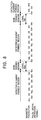
- variable LONG_TM1 is indicative of the elapse time from the current detection of the magnetic projection 52o to the current detection of the magnetic projection 52a. Further, the variable LONG_TM1 is indicative of the time corresponding to the time at which the non-formed region has currently passed near the crank angle sensor 16. Thus, the variable LONG_TM1 is referred to as the current non-formed-region passing time.
- variable LONG_TM2 is indicative of the elapse time from the previous detection of the magnetic projection 52o to the previous detection of the magnetic projection 52a. Further, the variable LONG_TM2 is indicative of the time corresponding to the time at which the non-formed region has previously passed near the crank angle sensor 16. Thus, the variable LONG TM2 is referred to as the previous non-formed-region passing time.
- Fig. 9 is a flowchart illustrating the subroutine for determining the stroke of the internal combustion engine to be executed in the aforementioned step S30 of Fig. 3.
- the parameter read routine described later, shown in Fig. 10 is executed to read parameters (step S61), and then executed is the routine for determining the stability of an internal combustion engine, described later, shown in Fig. 11 (step S62). Then, it is determined whether the flag F_STBL has a value of one (step S63).
- This flag F_STBL is indicative of whether the internal combustion engine provides stable operation. As described later, the flag F_STBL has a value of one when it is determined that the internal combustion engine operates with stability, whereas the flag F_STBL has a value of zero when it has been determined that the internal combustion engine is not stable in operation.
- step S63 it is determined whether the aforementioned variable LONG_TM1 is less than the variable LONG_TM2 (step S64).
- the flag F_IG is set to a value of zero (step S65)
- the flag F_720STG is set to a value of one (step S66)
- this subroutine is terminated.
- the flag F_IG is indicative of the permission of ignition.
- the flag F_IG takes on a value of one when it is determined that an ignition is to be produced in the current stroke, while the flag F_IG takes on a value of zero when no ignition is to be produced in the current stroke.
- step S67 When it has been determined in the aforementioned step S64 that the variable LONG_TM1 is equal to or greater than the variable LONG_TM2, it is determined whether the variable LONG_TM1 is greater than the variable LONG_TM2 (step S67). When it has been determined that the variable LONG_TM1 is greater than the variable LONG_TM2, the flag F_IG is set to a value of one (step S68), the flag F_720STG is set to a value of one (step S69), and then this subroutine is terminated.
- step S67 when it has been determined in step S67 that the variable LONG_TM1 is equal to or less than the variable LONG_TM2, the flag F_IG is set to a value of one (step S70), the flag F_720STG is set to a value of zero (step S71), and then this subroutine is terminated.
- the aforementioned magnetic projections 52o, 52a, shown in Fig. 8, form two neighboring detected elements which sandwich the non-formed region, the magnetic projection 52o forming one detected element and the magnetic projection 52a forming the other.
- the difference between the times at which these magnetic projections have passed previously near the crank angle sensor 16 is employed as the previous non-formed-region passing time LONG_TM2.
- the difference between the times at which these magnetic projections have passed currently near the crank angle sensor 16 is employed as the current non-formed-region passing time LONG_TM1.
- this current non-formed-region passing time LONG_TM1 is less than the previous non-formed-region passing time LONG_TM2, it is determined that the stroke of the internal combustion engine is in the combustion stroke.
- step S72 it is determined whether the flag F_720STG has a value of one.
- step S73 it is determined whether the flag F_IG has a value of one.
- step S74 the flag F_IG is set to a value of zero (step S75) and then this subroutine is terminated.
- step S72 when it has been determined in the aforementioned step S72 that the flag F_720STG does not have a value of one, the flag F_IG is set to a value of one (step S75) and then this subroutine is terminated.
- the expansion stroke requires less time than for the intake stroke.
- the non-formed region is so provided on the rotor 50 as to correspond to the expansion stroke or the intake stroke. This makes the elapse time over the non-formed region in the expansion stroke shorter than that in the intake stroke.
- steps S64 or S67 this makes it possible to determine, when it has been determined that the current non-formed-region passing time is shorter than the previous non-formed-region passing time, that the current stroke is the expansion stroke and the previous stroke is the intake stroke.
- the current non-formed-region passing time is determined to be longer than the previous non-formed-region passing time, it can be determined that the current stroke is the intake stroke and the previous stroke is the expansion stroke.
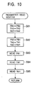
- Fig. 10 is a flowchart illustrating a subroutine for reading a parameter to be executed in the aforementioned step S61 of Fig. 9.
- the value of PB2 is substituted into a variable PB3, the value of TH2 is substituted into a variable TH3, and the value of Ne2 is substituted into a variable Ne3 (step S81).
- the aforementioned PB3 is indicative of the value of the negative pressure of the intake pipe that has been detected second previously.
- the PB2 is indicative of the negative pressure of the intake pipe that has been detected previously.
- the TH3 is indicative of the value of the opening level of the throttle valve that has been detected second previously.
- the TH2 is indicative of the value of the opening level of the throttle valve that has been detected previously.
- the Ne3 is indicative of the value of the rotational speed of the internal combustion engine that has been detected second previously.
- the Ne2 is indicative of the value of the rotational speed of the internal combustion engine that has been detected previously.
- the value of PB1 is substituted into the variable PB2, the value of TH1 is substituted into the variable TH2, and the value of Ne1 is substituted into the variable Ne2 (step S82).
- the PB1 is indicative of the value of the negative pressure of the intake pipe that has been detected currently.
- the TH1 is indicative of the value of the opening level of the throttle valve that has been detected currently.
- the Ne1 is indicative of the value of the rotational speed of the internal combustion engine that is detected currently.
- the value of the negative pressure of the intake pipe is detected and substituted into the PB1 (step S83) and the value of the opening level of the throttle valve is detected and substituted into the TH1 (step S84).
- the value of the rotational speed of the internal combustion engine is detected and substituted into the Ne1 (step S85) and then this subroutine is terminated.
- the aforementioned negative pressure of the intake pipe varies in accordance with the cycle of the internal combustion engine. As described later, the negative pressure of the intake pipe is detected to determine the stability of the internal combustion engine.
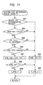
- Fig. 11 is a flowchart illustrating a subroutine for determining the stability of an internal combustion engine to be executed in the aforementioned step S62 of Fig. 9.
- step S91 it is determined whether the values of the rotational speed of the engine, the opening level of the throttle valve, and the negative pressure of the intake pipe are included within the predetermined range.
- the variable STBL_CNT is set to a value of zero (step S92)
- the flag F_STBL is set to a value of zero (step S93), and this subroutine is terminated.
- the variable STBL_CNT is indicative of the number of times at which it has been determined in this subroutine that the internal combustion engine is stable.
- the flag F_STBL is indicative of whether it has been determined that the internal combustion engine is stable. When it has been determined that the internal combustion engine is stable, the flag F_STBL has a value of one. On the other hand, when it has been determined that the internal combustion engine is not stable, the flag F_STBL has a value of zero.
- step S94 it is determined whether the absolute value of the difference between the second previous rotational speed Ne3 of the engine and the current rotational speed Ne1 of the engine is less than a predetermined rotational speed, for example, 20rpm.
- a predetermined rotational speed for example, 20rpm.
- step S94 it has been determined in step S94 that the absolute value of the difference between the Ne3 and Ne1 is less than the predetermined rotational speed.
- a predetermined opening level for example, 0.1 degrees
- step S95 it has been determined in step S95 that the absolute value of the difference between the TH3 and TH1 is less than the predetermined opening level.
- a predetermined opening level for example, 20mmHg
- the aforementioned processing of the steps S92 and S93 is executed and then this subroutine is terminated.
- the negative pressure of the intake pipe of a single cylinder internal combustion engine varies in accordance with the cycle of the internal combustion engine.
- this subroutine is to be executed in step S62 of the subroutine for determining an engine stroke shown in Fig. 9.
- the subroutine for determining an engine stroke is to be executed when it has been determined that the stage number is 14, as shown in steps S28 and S30 of the interrupt processing subroutine shown in Fig. 3.
- the negative pressure of the intake pipe is detected in a predetermined cycle of the internal combustion engine, thereby making it possible to determine the stability of the internal combustion engine in accordance with the value of the negative pressure of the intake pipe.
- step S96 When it has been determined in step S96 that the absolute value of the difference between the PB3 and PB1 is less than the predetermined value, the variable STBL_CNT is increased by one (step S97) and then it is determined whether the variable STBL_CNT is greater than two. (step S98). When it has been determined that the variable STBL_CNT is less than the predetermined number of times, for example, two times, the processing of the aforementioned steps S93 is performed and then this subroutine is terminated. On the other hand, when it has been determined that the variable STBL_CNT is greater than two, the flag F_STBL is set to a value of one (step S99) and then this subroutine is terminated.
- the equal angle interval of a plurality of detected elements or the magnetic projections is 20 degrees and the angle interval in the non-formed region is 80 degrees. It is also acceptable that the equal angle interval or the angle interval in the non-formed region may employ other angle intervals to provide the magnetic projections and the non-formed region.
- the stroke discriminator of the internal combustion engine according to the present invention makes it possible to quickly identify the stroke of an internal combustion engine with a simple configuration.
Landscapes
- Engineering & Computer Science (AREA)
- Chemical & Material Sciences (AREA)
- Combustion & Propulsion (AREA)
- Physics & Mathematics (AREA)
- General Physics & Mathematics (AREA)
- Mechanical Engineering (AREA)
- General Engineering & Computer Science (AREA)
- Combined Controls Of Internal Combustion Engines (AREA)
- Ignition Installations For Internal Combustion Engines (AREA)
- Length Measuring Devices With Unspecified Measuring Means (AREA)
Abstract
Description
Claims (3)
- A stroke discriminator for an internal combustion engine comprisinga rotor operatively associated with a crankshaft of a single cylinder internal combustion engine and provided with a plurality of detected elements thereon,detector means for transmitting a detection signal every time said detected elements pass the detector means, anddiscriminator means for determining a stroke of the internal combustion engine in accordance with a difference in time between a transmission of a previous detection signal and transmission of a current detection signal, whereinan outer periphery of said rotor is provided with a detected-element formed region having said plurality of detected elements formed thereon at equal angle intervals in a direction of rotation and a non-formed region having no detected elements formed thereon, andsaid non-formed region has an angle interval greater than said equal angle interval, and said non-formed region is provided on said rotor so as to pass near said detector means when a piston of said internal combustion engine travels from a top dead center position to a bottom dead center position.
- The stroke discriminator for an internal combustion engine according to Claim 1, wherein
said discriminator means calculate a difference in time between a time at which one of two neighboring detected elements, sandwiching said non-formed region passes the detector means and a time at which the other of said two detected elements passes the detector means, and an expansion stroke discriminator means is provided for determining that a stroke of said internal combustion engine is an expansion stroke when a difference in time given by said non-formed region currently passing near the detector means is less than a difference in time given by said non-formed region previously passing near the detector means. - The stroke discriminator of an internal combustion engine according to Claim 1, wherein
said discriminator means include expansion stroke discriminator means for calculating a first difference in time between a time at which a first detected element of two or more detected elements passing near the detector means and a time at which the second detected element of said two or more detected elements passes the detector means when said piston approaches from said bottom dead center position to said top dead center position;
for calculating a second difference in time between a time at which any one of two neighboring detected elements, sandwiching said non-formed region, passes near the detector means after said first detected element and said second detected element have passed the detector means and a time at which the detected element adjacent to said one detected element at said equal angle interval passes near the detector means, and,
for determining that the stroke of said internal combustion engine is an expansion stroke when a ratio of said second difference in time to said first difference in time is greater than a predetermined value.
Applications Claiming Priority (2)
| Application Number | Priority Date | Filing Date | Title |
|---|---|---|---|
| JP2000265502A JP3869198B2 (en) | 2000-09-01 | 2000-09-01 | Internal combustion engine stroke discrimination device |
| JP2000265502 | 2000-09-01 |
Publications (3)
| Publication Number | Publication Date |
|---|---|
| EP1184655A2 true EP1184655A2 (en) | 2002-03-06 |
| EP1184655A3 EP1184655A3 (en) | 2003-12-10 |
| EP1184655B1 EP1184655B1 (en) | 2006-09-13 |
Family
ID=18752757
Family Applications (1)
| Application Number | Title | Priority Date | Filing Date |
|---|---|---|---|
| EP01118361A Expired - Lifetime EP1184655B1 (en) | 2000-09-01 | 2001-07-27 | Stroke discriminator for an internal combustion engine |
Country Status (6)
| Country | Link |
|---|---|
| US (1) | US6595044B2 (en) |
| EP (1) | EP1184655B1 (en) |
| JP (1) | JP3869198B2 (en) |
| DE (1) | DE60122988T2 (en) |
| ES (1) | ES2272387T3 (en) |
| TW (1) | TW483983B (en) |
Families Citing this family (10)
| Publication number | Priority date | Publication date | Assignee | Title |
|---|---|---|---|---|
| JP4061951B2 (en) * | 2001-05-16 | 2008-03-19 | 国産電機株式会社 | 4-stroke internal combustion engine stroke determination method and apparatus |
| TW558609B (en) * | 2001-10-19 | 2003-10-21 | Yamaha Motor Co Ltd | Engine crank angle detecting device |
| DE10201430A1 (en) * | 2002-01-16 | 2003-08-14 | Siemens Ag | Procedure for reversing the direction of rotation in two-stroke engines |
| JP4014580B2 (en) * | 2004-04-02 | 2007-11-28 | 株式会社ケーヒン | Ignition timing control device for internal combustion engine |
| JP4539562B2 (en) * | 2006-01-06 | 2010-09-08 | 株式会社デンソー | Control device for single-cylinder four-cycle engine |
| JP2008309038A (en) * | 2007-06-13 | 2008-12-25 | Denso Corp | Single cylinder engine stroke discrimination method and stroke discrimination device |
| JP2009235963A (en) * | 2008-03-26 | 2009-10-15 | Honda Motor Co Ltd | Method and device for detecting crank angle of engine |
| JP5708347B2 (en) * | 2011-07-29 | 2015-04-30 | 株式会社デンソー | Single cylinder engine stroke discrimination device |
| JP7250067B2 (en) * | 2021-06-09 | 2023-03-31 | 三菱電機株式会社 | Control device for internal combustion engine |
| CN116085130A (en) * | 2022-12-26 | 2023-05-09 | 廊坊金润智通科技有限公司 | A method for judging engine stroke state |
Family Cites Families (2)
| Publication number | Priority date | Publication date | Assignee | Title |
|---|---|---|---|---|
| US4553427A (en) * | 1983-03-08 | 1985-11-19 | Nippondenso Co., Ltd. | Rotational reference position detection apparatus |
| US6035826A (en) * | 1997-09-30 | 2000-03-14 | Toyota Jidosha Kabushiki Kaisha | Crank angle detecting apparatus of internal combustion engine |
-
2000
- 2000-09-01 JP JP2000265502A patent/JP3869198B2/en not_active Expired - Fee Related
-
2001
- 2001-07-27 DE DE60122988T patent/DE60122988T2/en not_active Expired - Lifetime
- 2001-07-27 EP EP01118361A patent/EP1184655B1/en not_active Expired - Lifetime
- 2001-07-27 ES ES01118361T patent/ES2272387T3/en not_active Expired - Lifetime
- 2001-08-01 US US09/918,574 patent/US6595044B2/en not_active Expired - Fee Related
- 2001-08-03 TW TW090119008A patent/TW483983B/en not_active IP Right Cessation
Also Published As
| Publication number | Publication date |
|---|---|
| EP1184655B1 (en) | 2006-09-13 |
| EP1184655A3 (en) | 2003-12-10 |
| US20020026825A1 (en) | 2002-03-07 |
| DE60122988D1 (en) | 2006-10-26 |
| US6595044B2 (en) | 2003-07-22 |
| JP2002070708A (en) | 2002-03-08 |
| JP3869198B2 (en) | 2007-01-17 |
| DE60122988T2 (en) | 2007-05-24 |
| TW483983B (en) | 2002-04-21 |
| ES2272387T3 (en) | 2007-05-01 |
Similar Documents
| Publication | Publication Date | Title |
|---|---|---|
| JP3646312B2 (en) | Cylinder discrimination device for internal combustion engine | |
| JP4163114B2 (en) | Engine control device | |
| JP2648928B2 (en) | Cylinder discriminating apparatus and control method for each cylinder of automobile engine | |
| KR970066019A (en) | Engine combustion status determination method, engine control method and apparatus | |
| EP1184655B1 (en) | Stroke discriminator for an internal combustion engine | |
| EP1541845A1 (en) | Engine control device | |
| US5267544A (en) | Crank angle and cylinder number detecting system and method for internal combustion engine | |
| JP4825786B2 (en) | 4-cycle engine stroke discrimination device | |
| JP4248145B2 (en) | How to control ignition | |
| US20040107041A1 (en) | Vehicle control system | |
| JPH0676637U (en) | Electronic control device for fuel injection of diesel internal combustion engine | |
| EP1431574B1 (en) | Detection of engine rotation speed in spark ignition internal combustion engine | |
| KR940001936B1 (en) | Ignition control apparatus and method for an internal combustion engine | |
| CN101578606B (en) | Method and system for identifying phase in an internal combustion engine | |
| JP2004353598A (en) | Air-fuel ratio control device for internal combustion engine | |
| JP3092454B2 (en) | Ignition timing control device for internal combustion engine | |
| JPH07109948A (en) | Crank angle judging device for internal combustion engine | |
| KR100302800B1 (en) | Method for determining fuel injection timing and ignition timing in failure of crank angle sensor | |
| JPH03971A (en) | Ignition timing control device for internal combustion engine | |
| JP2625681B2 (en) | Fuel injection timing control device for internal combustion engine | |
| JP4148142B2 (en) | Spark plug ignition control method | |
| JPH05231294A (en) | Cylinder discrimination apparatus for internal combustion engine, internal combustion engine control apparatus using the same, and sensor apparatus | |
| JP2000027699A (en) | Method and device for discriminating engine cylinder in internal combustion engine | |
| KR0168373B1 (en) | Cylinder discriminating device of internal combustion engine | |
| JPH0631603B2 (en) | Ignition timing control device for internal combustion engine |
Legal Events
| Date | Code | Title | Description |
|---|---|---|---|
| PUAI | Public reference made under article 153(3) epc to a published international application that has entered the european phase |
Free format text: ORIGINAL CODE: 0009012 |
|
| AK | Designated contracting states |
Kind code of ref document: A2 Designated state(s): AT BE CH CY DE DK ES FI FR GB GR IE IT LI LU MC NL PT SE TR |
|
| AX | Request for extension of the european patent |
Free format text: AL;LT;LV;MK;RO;SI |
|
| PUAL | Search report despatched |
Free format text: ORIGINAL CODE: 0009013 |
|
| AK | Designated contracting states |
Kind code of ref document: A3 Designated state(s): AT BE CH CY DE DK ES FI FR GB GR IE IT LI LU MC NL PT SE TR |
|
| AX | Request for extension of the european patent |
Extension state: AL LT LV MK RO SI |
|
| 17P | Request for examination filed |
Effective date: 20040525 |
|
| AKX | Designation fees paid |
Designated state(s): DE ES FR GB IT |
|
| 17Q | First examination report despatched |
Effective date: 20040902 |
|
| GRAP | Despatch of communication of intention to grant a patent |
Free format text: ORIGINAL CODE: EPIDOSNIGR1 |
|
| RIC1 | Information provided on ipc code assigned before grant |
Ipc: G01M 15/06 20060101AFI20060106BHEP |
|
| GRAS | Grant fee paid |
Free format text: ORIGINAL CODE: EPIDOSNIGR3 |
|
| GRAA | (expected) grant |
Free format text: ORIGINAL CODE: 0009210 |
|
| AK | Designated contracting states |
Kind code of ref document: B1 Designated state(s): DE ES FR GB IT |
|
| PG25 | Lapsed in a contracting state [announced via postgrant information from national office to epo] |
Ref country code: IT Free format text: LAPSE BECAUSE OF FAILURE TO SUBMIT A TRANSLATION OF THE DESCRIPTION OR TO PAY THE FEE WITHIN THE PRESCRIBED TIME-LIMIT;WARNING: LAPSES OF ITALIAN PATENTS WITH EFFECTIVE DATE BEFORE 2007 MAY HAVE OCCURRED AT ANY TIME BEFORE 2007. THE CORRECT EFFECTIVE DATE MAY BE DIFFERENT FROM THE ONE RECORDED. Effective date: 20060913 |
|
| REG | Reference to a national code |
Ref country code: GB Ref legal event code: FG4D |
|
| REF | Corresponds to: |
Ref document number: 60122988 Country of ref document: DE Date of ref document: 20061026 Kind code of ref document: P |
|
| ET | Fr: translation filed | ||
| REG | Reference to a national code |
Ref country code: ES Ref legal event code: FG2A Ref document number: 2272387 Country of ref document: ES Kind code of ref document: T3 |
|
| PLBE | No opposition filed within time limit |
Free format text: ORIGINAL CODE: 0009261 |
|
| STAA | Information on the status of an ep patent application or granted ep patent |
Free format text: STATUS: NO OPPOSITION FILED WITHIN TIME LIMIT |
|
| 26N | No opposition filed |
Effective date: 20070614 |
|
| PGFP | Annual fee paid to national office [announced via postgrant information from national office to epo] |
Ref country code: FR Payment date: 20110727 Year of fee payment: 11 |
|
| PGFP | Annual fee paid to national office [announced via postgrant information from national office to epo] |
Ref country code: GB Payment date: 20110727 Year of fee payment: 11 Ref country code: DE Payment date: 20110720 Year of fee payment: 11 Ref country code: ES Payment date: 20110722 Year of fee payment: 11 |
|
| PGFP | Annual fee paid to national office [announced via postgrant information from national office to epo] |
Ref country code: IT Payment date: 20110720 Year of fee payment: 11 |
|
| GBPC | Gb: european patent ceased through non-payment of renewal fee |
Effective date: 20120727 |
|
| REG | Reference to a national code |
Ref country code: FR Ref legal event code: ST Effective date: 20130329 |
|
| PG25 | Lapsed in a contracting state [announced via postgrant information from national office to epo] |
Ref country code: DE Free format text: LAPSE BECAUSE OF NON-PAYMENT OF DUE FEES Effective date: 20130201 Ref country code: FR Free format text: LAPSE BECAUSE OF NON-PAYMENT OF DUE FEES Effective date: 20120731 Ref country code: GB Free format text: LAPSE BECAUSE OF NON-PAYMENT OF DUE FEES Effective date: 20120727 |
|
| PG25 | Lapsed in a contracting state [announced via postgrant information from national office to epo] |
Ref country code: IT Free format text: LAPSE BECAUSE OF NON-PAYMENT OF DUE FEES Effective date: 20120727 |
|
| REG | Reference to a national code |
Ref country code: DE Ref legal event code: R119 Ref document number: 60122988 Country of ref document: DE Effective date: 20130201 |
|
| REG | Reference to a national code |
Ref country code: ES Ref legal event code: FD2A Effective date: 20131018 |
|
| PG25 | Lapsed in a contracting state [announced via postgrant information from national office to epo] |
Ref country code: ES Free format text: LAPSE BECAUSE OF NON-PAYMENT OF DUE FEES Effective date: 20120728 |