EP1184610A2 - Multiple way valve - Google Patents
Multiple way valve Download PDFInfo
- Publication number
- EP1184610A2 EP1184610A2 EP01307227A EP01307227A EP1184610A2 EP 1184610 A2 EP1184610 A2 EP 1184610A2 EP 01307227 A EP01307227 A EP 01307227A EP 01307227 A EP01307227 A EP 01307227A EP 1184610 A2 EP1184610 A2 EP 1184610A2
- Authority
- EP
- European Patent Office
- Prior art keywords
- valve
- outlet ports
- seats
- valve seat
- inlet port
- Prior art date
- Legal status (The legal status is an assumption and is not a legal conclusion. Google has not performed a legal analysis and makes no representation as to the accuracy of the status listed.)
- Granted
Links
- 239000012530 fluid Substances 0.000 claims abstract description 43
- 230000002093 peripheral effect Effects 0.000 claims description 12
- 230000001419 dependent effect Effects 0.000 claims 1
- 239000007788 liquid Substances 0.000 description 4
- 238000002474 experimental method Methods 0.000 description 2
- 238000004519 manufacturing process Methods 0.000 description 2
- 238000007789 sealing Methods 0.000 description 2
- 230000015572 biosynthetic process Effects 0.000 description 1
- 230000000694 effects Effects 0.000 description 1
- 238000012856 packing Methods 0.000 description 1
- 238000005192 partition Methods 0.000 description 1
- 230000029058 respiratory gaseous exchange Effects 0.000 description 1
- XLYOFNOQVPJJNP-UHFFFAOYSA-N water Substances O XLYOFNOQVPJJNP-UHFFFAOYSA-N 0.000 description 1
Images


Classifications
-
- F—MECHANICAL ENGINEERING; LIGHTING; HEATING; WEAPONS; BLASTING
- F16—ENGINEERING ELEMENTS AND UNITS; GENERAL MEASURES FOR PRODUCING AND MAINTAINING EFFECTIVE FUNCTIONING OF MACHINES OR INSTALLATIONS; THERMAL INSULATION IN GENERAL
- F16K—VALVES; TAPS; COCKS; ACTUATING-FLOATS; DEVICES FOR VENTING OR AERATING
- F16K11/00—Multiple-way valves, e.g. mixing valves; Pipe fittings incorporating such valves
- F16K11/02—Multiple-way valves, e.g. mixing valves; Pipe fittings incorporating such valves with all movable sealing faces moving as one unit
-
- F—MECHANICAL ENGINEERING; LIGHTING; HEATING; WEAPONS; BLASTING
- F16—ENGINEERING ELEMENTS AND UNITS; GENERAL MEASURES FOR PRODUCING AND MAINTAINING EFFECTIVE FUNCTIONING OF MACHINES OR INSTALLATIONS; THERMAL INSULATION IN GENERAL
- F16K—VALVES; TAPS; COCKS; ACTUATING-FLOATS; DEVICES FOR VENTING OR AERATING
- F16K11/00—Multiple-way valves, e.g. mixing valves; Pipe fittings incorporating such valves
- F16K11/02—Multiple-way valves, e.g. mixing valves; Pipe fittings incorporating such valves with all movable sealing faces moving as one unit
- F16K11/04—Multiple-way valves, e.g. mixing valves; Pipe fittings incorporating such valves with all movable sealing faces moving as one unit comprising only lift valves
- F16K11/044—Multiple-way valves, e.g. mixing valves; Pipe fittings incorporating such valves with all movable sealing faces moving as one unit comprising only lift valves with movable valve members positioned between valve seats
-
- F—MECHANICAL ENGINEERING; LIGHTING; HEATING; WEAPONS; BLASTING
- F16—ENGINEERING ELEMENTS AND UNITS; GENERAL MEASURES FOR PRODUCING AND MAINTAINING EFFECTIVE FUNCTIONING OF MACHINES OR INSTALLATIONS; THERMAL INSULATION IN GENERAL
- F16K—VALVES; TAPS; COCKS; ACTUATING-FLOATS; DEVICES FOR VENTING OR AERATING
- F16K31/00—Actuating devices; Operating means; Releasing devices
- F16K31/12—Actuating devices; Operating means; Releasing devices actuated by fluid
- F16K31/122—Actuating devices; Operating means; Releasing devices actuated by fluid the fluid acting on a piston
- F16K31/1221—Actuating devices; Operating means; Releasing devices actuated by fluid the fluid acting on a piston one side of the piston being spring-loaded
-
- Y—GENERAL TAGGING OF NEW TECHNOLOGICAL DEVELOPMENTS; GENERAL TAGGING OF CROSS-SECTIONAL TECHNOLOGIES SPANNING OVER SEVERAL SECTIONS OF THE IPC; TECHNICAL SUBJECTS COVERED BY FORMER USPC CROSS-REFERENCE ART COLLECTIONS [XRACs] AND DIGESTS
- Y10—TECHNICAL SUBJECTS COVERED BY FORMER USPC
- Y10T—TECHNICAL SUBJECTS COVERED BY FORMER US CLASSIFICATION
- Y10T137/00—Fluid handling
- Y10T137/8593—Systems
- Y10T137/86493—Multi-way valve unit
- Y10T137/86879—Reciprocating valve unit
- Y10T137/86895—Plural disk or plug
Definitions
- the present invention relates to a three-port fluid selector valve and particularly to a fluid selector valve having a large flow coefficient but compact structure.
- a conventional and well known three-port fluid selector valve for selectively allowing fluid such as liquid which has flowed from an inlet port into a valve chamber to flow out of one of two outlet ports has valve seats communicating with the two outlet ports provided in a wall of the valve chamber into which the fluid flows from the inlet port and a poppet-type valve body disposed in the valve chamber and selectively seated on the valve seats to connect the inlet port to one of the outlet ports and to close the other of the outlet ports.
- a three-port fluid selector valve for selectively allowing fluid which has flowed from an inlet port into a valve chamber in a valve casing to flow out of two outlet ports on opposite sides of the inlet port, valve seats communicating with the respective outlet ports being respectively provided in positions of a wall of the valve chamber facing each other and a poppet-type valve body for connecting the inlet port to one of the outlet ports while closing the other of the outlet ports by being selectively seated on the two valve seats, wherein the valve seats are provided to inner bottom portions of valve seat holes formed on the valve chamber wall and the depth of each the valve seat hole is equal to or greater than a half of a thickness of an outer peripheral portion of the valve body.
- the present invention is based on the finding that it is possible to sufficiently enhance the flow coefficient by minimising the sharpness of throttles in portions where sharp throttles are formed and, preferably specifically in a portion where a sharp throttle is formed by projection of a portion of the valve body at the rear of the valve body into the flow path,portions where sharp throttles are formed due to provision of the valve seats, and the like.
- An advantage of the valve is that it is possible to minimise the sharpness of a sharp throttle due to projection of a rear portion of a valve body and throttles at valve seats thereby to enhance the flow coefficient of the fluid selector valve in accordance with the above finding.
- the valve has an enhanced flow coefficient and may have a structure which can be manufactured and assembled easily.
- a part of the wall of the valve chamber and a part of a peripheral wall of each of the two valve seat holes are formed of a continuous partial cylindrical face on a side opposite to the inlet port and that width s of a valve seat step which is the difference between an inside diameter D of each valve seat hole and an inside diameter d of each valve seat is s ⁇ 0.03d + 3 [mm].
- the valve casing is formed by joining an end block to a main body, the main body includes a flow path extending from the inlet port to one of the outlet ports through one of the valve seats, a rod slidable through the main body and having at a tip end a valve body so as to open and close the valve seats with the valve body, and driving means for driving the rod to seat the valve body on the valve seats, and the end block has the other valve seat and a flow path extending from the valve seat to the other outlet port.
- the fluid selector valve having the above structure selectively allows fluid which has flowed from the inlet port into the valve chamber in the valve casing to flow out of the two outlet ports on opposite sides of the inlet port. Because the valve seats provided in the flow paths extending to the outlet ports are provided at the inner bottom portions of the valve seat holes and each of the valve seat holes has the depth which is equal to or greater than the half of the thickness of the valve body, the back portion of the valve body seated on the valve seat does not project by a large distance into the flow path of fluid flowing through the other valve seat, and a sharp throttle is not formed in the flow path at the back portion. Therefore, it is possible to minimise sharpness of the throttle due to the valve body and to enhance the flow coefficient of the fluid selector valve.
- valve seats are provided on inner surfaces of opposite walls facing each other in the valve chamber so as to simplify the structure, the back portion of the valve body, when it is seated on the valve seat, projects into the valve chamber and sharply reduces the flow path of the fluid flowing from the inlet port through the open valve seat.
- the back portion of the valve body when it is seated on the valve seat, projects into the valve chamber and sharply reduces the flow path of the fluid flowing from the inlet port through the open valve seat.
- the inner wall face of the valve chamber and the peripheral wall faces of the two valve seat holes is formed as a continuous partial cylindrical face at a portion of the valve chamber wall facing the inlet port so as to facilitate processing of the valve chamber in the valve casing and to reduce the change of the flow path section. It is advantageous to minimise the width s of the valve seat step in the above-described range so as to decrease reduction of the flow coefficient due to throttling of the flow paths at the valve seats. Furthermore, by setting the radius R of curvature on the outer peripheral side of each of the elbow-shaped bends of the flow path extending from the valve seats to the respective ports in a value in the above-described range, it is possible to further decrease reduction of the flow coefficient.
- the fluid selector valve can have both a large flow coefficient and a compact structure.
- valve casing in the fluid selector valve is formed by joining the end block to the main body and the other valve seat is provided to the end block, it is possible to easily carry out processing of the valve chamber and the valve seat in the main body and assembly of the valve body through a hole of the main body which is then closed with the end block.
- This fluid selector valve is a three-port fluid selector valve for selectively allowing fluid such as liquid which has flowed from an inlet port into a valve casing to flow out of two outlet ports, includes as its main components a valve casing 1 formed by joining an end block 3 to a main body 2 and ports communicating with respective flow paths of the valve casing 1, and includes passing through the main body 2 and mounted at a tip end of the rod 6 with a poppet-type valve body 5, and driving means 7 for driving the rod 6.
- the valve casing 1 includes a valve chamber 12 into which fluid flows from the inlet port 41 of the sub-plate 4 through a flow path 11 and includes a pair of valve seats 13 and 31 on opposite walls facing each other of the valve chamber. Downstream from the valve seats 13 and 31, flow paths 15 and 16 communicating with the two outlet ports 42 and 43 on opposite sides of the inlet port 41 in the sub-plate 4 are provided respectively. Therefore, the sub-plate 4 is joined to the main body 2 with the inlet port 41 communicating with the flow path 11 of the main body 2 and the outlet ports 42 and 43 respectively communicating with the flow paths 15 and 16 of the main body 2.
- the inlet port 41 and the outlet ports 42 and 43 on opposite sides of the inlet port 41 in the sub-plate 4 open in directions opposite to each other as can be seen from FIGS. 3 to 5.
- the main body 2 includes a junction hole 14 in a position coaxial with the rod 6 retaining the valve body 5 and is joined to the end block 3 by fitting the end block 3 in the junction hole 14 and fixing a flange portion 33 to the main body.
- the one valve seat 13 is integrally or detachably provided to the main body 2 and the other valve seat 31 is mounted to the main body 2 with the end block 3.
- the end block 3 is provided with a flow path 32 extending from the valve seat 31 to communicate with the port 43 through the flow path 16 in the main body 2.
- the flow path 32 and the flow path 16 are formed to have a substantially uniform flow path cross-sectional area including the flow path in the valve seat 31. There is no harm in forming the valve seat 31 separately from the end block 3 as shown in the drawings or integrally with the end block 3.
- Both the valve seats 13 and 31 are provided at inner bottom portions of valve seat holes 17 and 18 formed in a wall of the valve chamber 12. Depths of the valve seat holes 17 and 18 are at least equal to or greater than a half of a thickness of an outer peripheral portion of the valve body 5.
- valve seat holes 17 and 18 of such depths that the entire thickness of the valve body 5 can be fitted in the holes would be even more effective in not forming the throttle in the flow path.
- such depths would result in having to increase the external size of the valve casing 1 to provide the valve seat holes 17 and 18. Therefore, it is advantageous to maximise the depths of the valve seat holes in such a way that the influence of the throttle in the flow path due to the valve body 5 on the flow coefficient does not become large.
- an advantageous range for the depths of the valve seat holes 17 and 18 is between about a half to one times the thickness of the outer periphery of the valve body 5. It is not preferable that the depths of the valve seat holes 17 and 18 are greater than the thickness of the valve body 5 because the change in the flow path section becomes large.
- an inner wall face 12a of the valve chamber wall facing the inlet port 41 is formed of a continuous partial cylindrical face with a part of hole peripheral wall faces of the two valve seat holes 17 and 18.
- the junction hole 14 for the end block 3 provided to the main body 2 is a cylindrical face with a larger diameter than at least the partial cylindrical face.
- valve chamber 12 It is not preferable to form a recessed portion in the inner wall face 12a of the valve chamber 12 to upsize the valve chamber 12 even if there is room in a wall thickness of the main body 2, because the flow paths from the valve chamber 12 are throttled by a large amount at the valve seats 13 and 31.
- the width s of a valve seat step which is a difference between an inside diameter D of each of the valve seat holes 17 and 18 and an inside diameter d of each of the valve seats 13 and 31.
- the width s of the valve seat step should be allowed for the width s of the valve seat step to have a width suitable for at least seating and sealing of the valve body 5 and manufacturing and assembly tolerances of the valve body 5.
- the width s may be 3mm, desirably 2mm, and empirically 0.03d[mm], though the width of the step s needs to be changed according to the inside diameter d of the valve seat when the diameter d increases.
- the width s may be in the following range. s ⁇ 0.03d + 3[mm]
- the flow paths extending from the two valve seats 13 and 31 to respectively communicate with the outlet ports 42 and 43 form elbow-shaped bends.
- the valve body 5 is mounted to a tip end of the rod 6 by fitting the disc-shaped poppet-type valve body 5 with the tip end of the rod 6 through a sealing member 51 and screwing a bolt 53 over the tip end of the rod through a holder 52.
- the rod 6 passes through the main body 2 and a support plate 21 mounted to the main body 2 through an O-ring 22 and extends outside from the valve casing 1.
- a pneumatically operated cylinder as the driving means 7 is attached such that the support plate 21 is covered with the cylinder.
- the rod 6 is inserted through a hole 23 provided to the support plate 21 in airtight and watertight states through an air seal 61, a liquid seal 62, and a scraper 63.
- the pneumatically operated cylinder is mounted to the main body 2 such that the support plate 21 is covered with the cylinder and includes a cover 71 having inside thereof a cylinder bore 72 and a piston 73 fixed to a base end of the rod 6 and fitted in the cylinder bore 72.
- the piston 73 partitions an inside of the cylinder bore 72 into a pilot chamber 74 on the main body 2 side and a back chamber 75 on an opposite side.
- the pilot chamber 74 communicates with a port (not shown) through which pilot compressed air is supplied and discharged and the back chamber 75 is open into the atmosphere through a breathing port (not shown).
- a return spring 76 for pushing the piston 73 toward the pilot chamber 74 when the compressed air is discharged from the pilot chamber 74 is housed.
- a wear ring 77 and piston packing 78 in sliding contact with an inner face of the cylinder bore 72 are provided.
- the driving means 7 is not limited to the abovedescribed pneumatically operated driving cylinder.
- the fluid selector valve having the above structure is formed to have the large flow coefficient while having a compact structure and selectively allows the fluid (liquid such as water and oil) which has flowed from the inlet port 41 into the valve chamber in the valve casing 1 to flow out of two outlet ports 42 and 43 by the valve body 5 driven by the driving means 7.
- the valve seats 13 and 31 provided in the flow paths are provided at the inner bottom portions of the valve seat holes 17 and 18 and each of the valve seat holes has the depth which is at least equal to or greater than the half of the thickness of the periphery of the valve body 5, the back portion of the valve body 5 seated on the valve seat 31 as shown in FIG. 1 does not project by the large distance into the flow path of fluid passing through the other valve seat 13 to form the sharp throttle in the flow path, for example.
- the portion of the inner wall face 12a of the valve chamber wall facing the inlet port 41 is formed of the continuous partial cylindrical face with the peripheral wall faces of the two valve seat holes 17 and 18, not only easy processing of the valve chamber 12 in the valve casing 1 but also reduction of the change in the flow path section is possible. Moreover, because the width s of the valve seat step is minimized in the above-described range, throttling of the flow paths at the valve seats 13 and 31 is also suppressed in this respect. Furthermore, by setting the radius R of curvature of each of the elbow-shaped bends in the flow paths extending from the two valve seats 13 and 31 to communicate with the respective outlet ports 42 and 43 at a value in the above-described range, it is possible to further suppress reduction of the flow coefficient.
- valve casing 1 is formed by joining the end block 3 to the main body 2 and the other valve seat 31 facing the one valve seat 13 provided to the main body 2 is provided to the end block 3, it is possible to easily carry out processing of the valve chamber 12 and the valve seat in the main body 2 and assembly of the valve body 5 through the junction hole 14 of the main body 2 closed with the end block 3.
Landscapes
- Engineering & Computer Science (AREA)
- General Engineering & Computer Science (AREA)
- Mechanical Engineering (AREA)
- Multiple-Way Valves (AREA)
Abstract
Description
- The present invention relates to a three-port fluid selector valve and particularly to a fluid selector valve having a large flow coefficient but compact structure.
- A conventional and well known three-port fluid selector valve for selectively allowing fluid such as liquid which has flowed from an inlet port into a valve chamber to flow out of one of two outlet ports has valve seats communicating with the two outlet ports provided in a wall of the valve chamber into which the fluid flows from the inlet port and a poppet-type valve body disposed in the valve chamber and selectively seated on the valve seats to connect the inlet port to one of the outlet ports and to close the other of the outlet ports.
- In such a fluid selector valve, the cross-sectional areas of a flow path extending from the inlet port to the valve chamber and in the valve chamber itself are increased so as to increase flow rate without upsizing the external shape. However, as a result of various experiments, it has been found that arbitral upsizing of the flow path does not effectively increase the flow rate and may produce a contrary effect if the result is formation of a stagnating portion or a portion where a flow path section is changed sharply and so disturbs flow.
- It is an object of the invention to provide a three-port fluid selector valve with a large flow coefficient but compact structure.
- In accordance with the invention there is provided a three-port fluid selector valve for selectively allowing fluid which has flowed from an inlet port into a valve chamber in a valve casing to flow out of two outlet ports on opposite sides of the inlet port, valve seats communicating with the respective outlet ports being respectively provided in positions of a wall of the valve chamber facing each other and a poppet-type valve body for connecting the inlet port to one of the outlet ports while closing the other of the outlet ports by being selectively seated on the two valve seats, wherein the valve seats are provided to inner bottom portions of valve seat holes formed on the valve chamber wall and the depth of each the valve seat hole is equal to or greater than a half of a thickness of an outer peripheral portion of the valve body.
- The present invention is based on the finding that it is possible to sufficiently enhance the flow coefficient by minimising the sharpness of throttles in portions where sharp throttles are formed and, preferably specifically in a portion where a sharp throttle is formed by projection of a portion of the valve body at the rear of the valve body into the flow path,portions where sharp throttles are formed due to provision of the valve seats, and the like.
- An advantage of the valve is that it is possible to minimise the sharpness of a sharp throttle due to projection of a rear portion of a valve body and throttles at valve seats thereby to enhance the flow coefficient of the fluid selector valve in accordance with the above finding.
- The valve has an enhanced flow coefficient and may have a structure which can be manufactured and assembled easily.
- In the fluid selector valve, it is appropriate that a part of the wall of the valve chamber and a part of a peripheral wall of each of the two valve seat holes are formed of a continuous partial cylindrical face on a side opposite to the inlet port and that width s of a valve seat step which is the difference between an inside diameter D of each valve seat hole and an inside diameter d of each valve seat is s ≤ 0.03d + 3 [mm]. It is also appropriate that elbow-shaped bends of the flow paths extending from the two valve seats to the outlet ports are formed such that a radius R of curvature of each bend on an outer peripheral side is R=0.5d to 1d.
- In a preferred embodiment, the valve casing is formed by joining an end block to a main body, the main body includes a flow path extending from the inlet port to one of the outlet ports through one of the valve seats, a rod slidable through the main body and having at a tip end a valve body so as to open and close the valve seats with the valve body, and driving means for driving the rod to seat the valve body on the valve seats, and the end block has the other valve seat and a flow path extending from the valve seat to the other outlet port.
- The fluid selector valve having the above structure selectively allows fluid which has flowed from the inlet port into the valve chamber in the valve casing to flow out of the two outlet ports on opposite sides of the inlet port. Because the valve seats provided in the flow paths extending to the outlet ports are provided at the inner bottom portions of the valve seat holes and each of the valve seat holes has the depth which is equal to or greater than the half of the thickness of the valve body, the back portion of the valve body seated on the valve seat does not project by a large distance into the flow path of fluid flowing through the other valve seat, and a sharp throttle is not formed in the flow path at the back portion. Therefore, it is possible to minimise sharpness of the throttle due to the valve body and to enhance the flow coefficient of the fluid selector valve.
- With known valves, if the valve seats are provided on inner surfaces of opposite walls facing each other in the valve chamber so as to simplify the structure, the back portion of the valve body, when it is seated on the valve seat, projects into the valve chamber and sharply reduces the flow path of the fluid flowing from the inlet port through the open valve seat. However, such a problem is solved by the above-described structure.
- It is advantageous to form the inner wall face of the valve chamber and the peripheral wall faces of the two valve seat holes as a continuous partial cylindrical face at a portion of the valve chamber wall facing the inlet port so as to facilitate processing of the valve chamber in the valve casing and to reduce the change of the flow path section. It is advantageous to minimise the width s of the valve seat step in the above-described range so as to decrease reduction of the flow coefficient due to throttling of the flow paths at the valve seats. Furthermore, by setting the radius R of curvature on the outer peripheral side of each of the elbow-shaped bends of the flow path extending from the valve seats to the respective ports in a value in the above-described range, it is possible to further decrease reduction of the flow coefficient.
- With the above structure, the fluid selector valve can have both a large flow coefficient and a compact structure.
- If the valve casing in the fluid selector valve is formed by joining the end block to the main body and the other valve seat is provided to the end block, it is possible to easily carry out processing of the valve chamber and the valve seat in the main body and assembly of the valve body through a hole of the main body which is then closed with the end block.
- The invention will now be described by way of example with reference to the accompanying drawings in which:
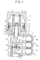
- FIG. 1 is a sectional view showing an embodiment of a fluid selector valve according to the present invention.
- FIG. 2 is a sectional view showing the valve in a second state.
- FIG. 3 is a sectional view taken along III-III in FIG. 1.
- FIG. 4 is a sectional view taken along IV-IV in FIG. 1.
- FIG. 5 is a sectional view taken along V-V in FIG. 1.
- FIGS. 1 to 5 show an embodiment of a fluid selector valve.
-
- This fluid selector valve is a three-port fluid selector valve for selectively allowing fluid such as liquid which has flowed from an inlet port into a valve casing to flow out of two outlet ports, includes as its main components a valve casing 1 formed by joining an end block 3 to a
main body 2 and ports communicating with respective flow paths of the valve casing 1, and includes passing through themain body 2 and mounted at a tip end of therod 6 with a poppet-type valve body 5, and driving means 7 for driving therod 6. - The valve casing 1 includes a
valve chamber 12 into which fluid flows from theinlet port 41 of the sub-plate 4 through aflow path 11 and includes a pair ofvalve seats valve seats flow paths outlet ports inlet port 41 in the sub-plate 4 are provided respectively. Therefore, the sub-plate 4 is joined to themain body 2 with theinlet port 41 communicating with theflow path 11 of themain body 2 and theoutlet ports flow paths main body 2. - The
inlet port 41 and theoutlet ports inlet port 41 in the sub-plate 4 open in directions opposite to each other as can be seen from FIGS. 3 to 5. - The
main body 2 includes ajunction hole 14 in a position coaxial with therod 6 retaining thevalve body 5 and is joined to the end block 3 by fitting the end block 3 in thejunction hole 14 and fixing aflange portion 33 to the main body. Of thevalve seats valve seat 13 is integrally or detachably provided to themain body 2 and theother valve seat 31 is mounted to themain body 2 with the end block 3. - The end block 3 is provided with a
flow path 32 extending from thevalve seat 31 to communicate with theport 43 through theflow path 16 in themain body 2. Theflow path 32 and theflow path 16 are formed to have a substantially uniform flow path cross-sectional area including the flow path in thevalve seat 31. There is no harm in forming thevalve seat 31 separately from the end block 3 as shown in the drawings or integrally with the end block 3. - Both the
valve seats valve chamber 12. Depths of the valve seat holes 17 and 18 are at least equal to or greater than a half of a thickness of an outer peripheral portion of thevalve body 5. Thus, in selectively allowing fluid which has flowed from theinlet port 41 into thevalve chamber 12 in themain body 2 to flow out of the twooutlet ports valve body 5 seated on any of thevalve seats open valve seat valve body 5 is made gentle, and a flow coefficient of the fluid selector valve can be enhanced. - Making the valve seat holes 17 and 18 of such depths that the entire thickness of the
valve body 5 can be fitted in the holes would be even more effective in not forming the throttle in the flow path. However, such depths would result in having to increase the external size of the valve casing 1 to provide the valve seat holes 17 and 18. Therefore, it is advantageous to maximise the depths of the valve seat holes in such a way that the influence of the throttle in the flow path due to thevalve body 5 on the flow coefficient does not become large. By experiments, it has been found that an advantageous range for the depths of the valve seat holes 17 and 18 is between about a half to one times the thickness of the outer periphery of thevalve body 5. It is not preferable that the depths of the valve seat holes 17 and 18 are greater than the thickness of thevalve body 5 because the change in the flow path section becomes large. - In the
valve chamber 12 in thevalve body 2, an inner wall face 12a of the valve chamber wall facing theinlet port 41 is formed of a continuous partial cylindrical face with a part of hole peripheral wall faces of the two valve seat holes 17 and 18. Thejunction hole 14 for the end block 3 provided to themain body 2 is a cylindrical face with a larger diameter than at least the partial cylindrical face. - Therefore, not only reduction of the change in the flow path section from the
valve chamber 12 to thevalve seats valve chamber 12 and thevalve seat 13 in themain body block 2 and assembly of thevalve body 5 through thejunction hole 14 of thevalve body 2 are possible. - It is not preferable to form a recessed portion in the inner wall face 12a of the
valve chamber 12 to upsize thevalve chamber 12 even if there is room in a wall thickness of themain body 2, because the flow paths from thevalve chamber 12 are throttled by a large amount at thevalve seats - It is desirable to reduce the change in the flow path section of fluid flowing from the valve seat holes 17 and 18 through the
valve seats valve seats valve body 5 and manufacturing and assembly tolerances of thevalve body 5. If the width and tolerances are taken into consideration, in a general-purpose fluid selector valve, the width s may be 3mm, desirably 2mm, and empirically 0.03d[mm], though the width of the step s needs to be changed according to the inside diameter d of the valve seat when the diameter d increases. - As a result, the width s may be in the following range.
- By minimizing the width s of the valve seat step in such a range, it is possible to suppress reduction of the flow coefficient due to throttling of the flow paths at the
valve seats - The flow paths extending from the two
valve seats outlet ports - The
valve body 5 is mounted to a tip end of therod 6 by fitting the disc-shaped poppet-type valve body 5 with the tip end of therod 6 through a sealingmember 51 and screwing abolt 53 over the tip end of the rod through a holder 52. Therod 6 passes through themain body 2 and asupport plate 21 mounted to themain body 2 through an O-ring 22 and extends outside from the valve casing 1. To themain body 2, a pneumatically operated cylinder as the driving means 7 is attached such that thesupport plate 21 is covered with the cylinder. Therod 6 is inserted through ahole 23 provided to thesupport plate 21 in airtight and watertight states through anair seal 61, aliquid seal 62, and ascraper 63. - The pneumatically operated cylinder is mounted to the
main body 2 such that thesupport plate 21 is covered with the cylinder and includes acover 71 having inside thereof acylinder bore 72 and apiston 73 fixed to a base end of therod 6 and fitted in thecylinder bore 72. Thepiston 73 partitions an inside of the cylinder bore 72 into apilot chamber 74 on themain body 2 side and aback chamber 75 on an opposite side. Thepilot chamber 74 communicates with a port (not shown) through which pilot compressed air is supplied and discharged and theback chamber 75 is open into the atmosphere through a breathing port (not shown). In theback chamber 75, areturn spring 76 for pushing thepiston 73 toward thepilot chamber 74 when the compressed air is discharged from thepilot chamber 74 is housed. Around the piston 3, awear ring 77 and piston packing 78 in sliding contact with an inner face of the cylinder bore 72 are provided. - The driving means 7 is not limited to the abovedescribed pneumatically operated driving cylinder.
- The fluid selector valve having the above structure is formed to have the large flow coefficient while having a compact structure and selectively allows the fluid (liquid such as water and oil) which has flowed from the
inlet port 41 into the valve chamber in the valve casing 1 to flow out of twooutlet ports valve body 5 driven by the driving means 7. Because the valve seats 13 and 31 provided in the flow paths are provided at the inner bottom portions of the valve seat holes 17 and 18 and each of the valve seat holes has the depth which is at least equal to or greater than the half of the thickness of the periphery of thevalve body 5, the back portion of thevalve body 5 seated on thevalve seat 31 as shown in FIG. 1 does not project by the large distance into the flow path of fluid passing through theother valve seat 13 to form the sharp throttle in the flow path, for example. - Because the portion of the inner wall face 12a of the valve chamber wall facing the
inlet port 41 is formed of the continuous partial cylindrical face with the peripheral wall faces of the two valve seat holes 17 and 18, not only easy processing of thevalve chamber 12 in the valve casing 1 but also reduction of the change in the flow path section is possible. Moreover, because the width s of the valve seat step is minimized in the above-described range, throttling of the flow paths at the valve seats 13 and 31 is also suppressed in this respect. Furthermore, by setting the radius R of curvature of each of the elbow-shaped bends in the flow paths extending from the twovalve seats respective outlet ports - Because the valve casing 1 is formed by joining the end block 3 to the
main body 2 and theother valve seat 31 facing the onevalve seat 13 provided to themain body 2 is provided to the end block 3, it is possible to easily carry out processing of thevalve chamber 12 and the valve seat in themain body 2 and assembly of thevalve body 5 through thejunction hole 14 of themain body 2 closed with the end block 3. - With the fluid selector valve described above in detail, it is possible to obtain a large flow coefficient by minimising sharpness of the sharp throttle due to projection of the portion of the valve body at the back of the valve body and the throttle at each valve seat while making the structure of the selector valve compact and it is also possible to facilitate manufacturing and assembly of the fluid selector valve.
Claims (5)
- A three-port fluid selector valve for selectively allowing fluid which has flowed from an inlet port into a valve chamber in a valve casing to flow out of two outlet ports on opposite sides of the inlet port, valve seats communicating with the outlet ports being provided in a wall of the valve chamber in positions facing each other and a poppet-type valve body for connecting the inlet port to one of the outlet ports while closing the other of the outlet ports by being selectively seated on a respective one of the two valve seats, wherein the valve seats are provided in inner bottom portions of valve seat holes formed in the valve chamber wall and the depth of each valve seat hole is equal to or greater than a half of the thickness of an outer peripheral portion of the valve body.
- A fluid selector valve as claimed in Claim 1, wherein part of the valve chamber wall and part of a peripheral wall of each of the two valve seat holes are formed as a continuous partial cylindrical face on a side opposite to the inlet port.
- A fluid selector valve as claimed in either Claim 1 or Claim 2 wherein the width s of a valve seat step which is a difference between an inside diameter D of each valve seat hole and an inside diameter d of each valve seat is s ≤ 0.03d + 3 [mm].
- A fluid selector valve as claimed in any preceding claim, wherein the valve casing is formed by joining an end block to a main body, wherein the main body includes a flow path extending from the inlet port to one of the outlet ports through one of the valve seats, a rod slidable in the main body and having at a tip end of a valve body for opening and closing the valve seats with said valve body, and driving means for driving the rod to seat the valve body on the valve seats, and wherein the end block has the other valve seat and a flow path extending from the valve seat to the other outlet port.
- A fluid selector valve as claimed in Claim 4 when dependent on Claim 3, wherein elbow-shaped bends are formed in the flow paths extending from the two valve seats to the outlet ports and a radius R of curvature of each bend on an outer peripheral side is R=0.5d to 1d.
Applications Claiming Priority (3)
| Application Number | Priority Date | Filing Date | Title |
|---|---|---|---|
| JP2000257307 | 2000-08-28 | ||
| JP2000257309 | 2000-08-28 | ||
| JP2000257309A JP3602421B2 (en) | 2000-08-28 | 2000-08-28 | Fluid switching valve |
Publications (3)
| Publication Number | Publication Date |
|---|---|
| EP1184610A2 true EP1184610A2 (en) | 2002-03-06 |
| EP1184610A3 EP1184610A3 (en) | 2003-05-28 |
| EP1184610B1 EP1184610B1 (en) | 2007-02-07 |
Family
ID=18745786
Family Applications (1)
| Application Number | Title | Priority Date | Filing Date |
|---|---|---|---|
| EP01307227A Expired - Lifetime EP1184610B1 (en) | 2000-08-28 | 2001-08-24 | Multiple way valve |
Country Status (7)
| Country | Link |
|---|---|
| US (1) | US6536475B2 (en) |
| EP (1) | EP1184610B1 (en) |
| JP (1) | JP3602421B2 (en) |
| KR (1) | KR100499244B1 (en) |
| CN (1) | CN1224789C (en) |
| DE (1) | DE60126450T2 (en) |
| TW (1) | TW478580U (en) |
Cited By (3)
| Publication number | Priority date | Publication date | Assignee | Title |
|---|---|---|---|---|
| KR100499244B1 (en) * | 2000-08-28 | 2005-07-07 | 에스엠시 가부시키가이샤 | Fluid selector valve |
| EP2903929A1 (en) | 2012-10-05 | 2015-08-12 | Gai Macchine Imbottigliatrici S.p.A. | Filling device for isobaric filling machines for filling bottles with alimentary liquids |
| EP3892898A4 (en) * | 2018-12-05 | 2022-09-07 | Fujikoki Corporation | VALVE DEVICE |
Families Citing this family (15)
| Publication number | Priority date | Publication date | Assignee | Title |
|---|---|---|---|---|
| US20090032533A1 (en) * | 2006-07-06 | 2009-02-05 | Axial Technologies Ltd. | Flow switch and container |
| JP5002016B2 (en) * | 2006-09-26 | 2012-08-15 | フルーイッド・オートメーション・システムズ・ソシエテ・アノニム | Valve seal member and valve |
| JP4324946B2 (en) | 2007-03-13 | 2009-09-02 | Smc株式会社 | Pilot type 3 port valve |
| ATE538337T1 (en) * | 2008-11-18 | 2012-01-15 | Sauer Danfoss Aps | LIQUID DISTRIBUTION VALVE |
| AU2015271984B2 (en) * | 2009-09-04 | 2018-05-10 | Gea Farm Technologies, Inc. | Safety valve for an automatic dairy animal milker unit backflusher and teat dip applicator |
| DE102009050778A1 (en) | 2009-10-27 | 2011-04-28 | Robert Bosch Gmbh | Poppet valve has valve seat and plug consisting of valve piston and separate piston foot in form of valve disk or valve plate |
| CN102128282B (en) * | 2010-01-14 | 2012-11-28 | 长沙理工大学 | Pressure control switching valve |
| CN104583681A (en) * | 2012-07-30 | 2015-04-29 | 艾菲卡克斯能量股份公司 | System, module and valve for domestic hot water heaters |
| KR102270597B1 (en) * | 2014-04-02 | 2021-06-29 | 배트 홀딩 아게 | Vacuum valve |
| US10508745B2 (en) * | 2015-09-18 | 2019-12-17 | The Oilgear Company | Valve assembly |
| CN107881710B (en) | 2016-09-30 | 2023-11-03 | 杭州神林电子有限公司 | Flow path switcher and liquid detergent dispensing device |
| CN107314125B (en) * | 2017-07-14 | 2023-12-22 | 浙江华益精密机械有限公司 | Step type three-way switching valve |
| JP7006525B2 (en) * | 2018-06-28 | 2022-01-24 | 株式会社デンソー | Valve device and vehicle cleaning system |
| CN119084661A (en) * | 2024-09-14 | 2024-12-06 | 东莞市聚瑞电气技术有限公司 | A three-way gas-controlled valve |
| CN119196344A (en) * | 2024-11-28 | 2024-12-27 | 中齐能源科技有限公司 | Integrated quick response two-way valve |
Family Cites Families (15)
| Publication number | Priority date | Publication date | Assignee | Title |
|---|---|---|---|---|
| US1442782A (en) * | 1919-01-15 | 1923-01-16 | Carl F Braun | Three-way by-pass valve |
| US2911995A (en) * | 1956-07-30 | 1959-11-10 | Preising Richard William | Valve having alternative closing positions and a reversible, double faced valve element |
| US2914035A (en) * | 1957-04-29 | 1959-11-24 | New Prod Corp | Open center valve with limited reaction |
| US3134395A (en) * | 1960-02-18 | 1964-05-26 | Nat Tank Co | Manifold valve |
| US4078579A (en) * | 1976-08-26 | 1978-03-14 | Frank E. Goodwin | Multiple port fluid control device |
| US4262698A (en) * | 1979-12-26 | 1981-04-21 | Yardney Electric Corporation | Valve |
| AU531158B2 (en) * | 1981-08-07 | 1983-08-11 | Mac Valves, Inc. | Three-way normally closed pilot valve |
| US4852612A (en) * | 1983-09-23 | 1989-08-01 | Bucko Sr Edward P | Fluid flow control device |
| JPH0615186Y2 (en) * | 1986-12-29 | 1994-04-20 | エスエムシー株式会社 | Direction switching valve |
| JPH04125376A (en) * | 1990-09-11 | 1992-04-24 | Matsushita Electric Ind Co Ltd | Solenoid controlled switching valve |
| DE19509765A1 (en) * | 1995-03-17 | 1996-09-19 | Pommerening Armaturenwerk Gmbh | Flow temperature regulation for heating circuit |
| KR20000027414A (en) * | 1998-10-28 | 2000-05-15 | 윤종용 | Pneumatic valve |
| US6209582B1 (en) * | 2000-05-26 | 2001-04-03 | Honeywell Commercial Vehicle Systems Company | 2-way collar and O-ring seal assembly |
| JP3602421B2 (en) * | 2000-08-28 | 2004-12-15 | Smc株式会社 | Fluid switching valve |
| DE102016107624A1 (en) * | 2016-03-22 | 2017-09-28 | Förster Technik GmbH | Method of displaying information on an animal and finding an animal |
-
2000
- 2000-08-28 JP JP2000257309A patent/JP3602421B2/en not_active Expired - Fee Related
-
2001
- 2001-08-03 TW TW090213238U patent/TW478580U/en not_active IP Right Cessation
- 2001-08-06 US US09/921,558 patent/US6536475B2/en not_active Expired - Fee Related
- 2001-08-24 DE DE60126450T patent/DE60126450T2/en not_active Expired - Fee Related
- 2001-08-24 EP EP01307227A patent/EP1184610B1/en not_active Expired - Lifetime
- 2001-08-27 KR KR10-2001-0051649A patent/KR100499244B1/en not_active Expired - Fee Related
- 2001-08-28 CN CNB011258594A patent/CN1224789C/en not_active Expired - Fee Related
Non-Patent Citations (1)
| Title |
|---|
| None |
Cited By (5)
| Publication number | Priority date | Publication date | Assignee | Title |
|---|---|---|---|---|
| KR100499244B1 (en) * | 2000-08-28 | 2005-07-07 | 에스엠시 가부시키가이샤 | Fluid selector valve |
| EP2903929A1 (en) | 2012-10-05 | 2015-08-12 | Gai Macchine Imbottigliatrici S.p.A. | Filling device for isobaric filling machines for filling bottles with alimentary liquids |
| EP2903929B1 (en) * | 2012-10-05 | 2017-02-15 | Gai Macchine Imbottigliatrici S.p.A. | Filling device for isobaric filling machines for filling bottles with alimentary liquids |
| EP3892898A4 (en) * | 2018-12-05 | 2022-09-07 | Fujikoki Corporation | VALVE DEVICE |
| EP4428413A3 (en) * | 2018-12-05 | 2024-12-04 | Fujikoki Corporation | Valve device |
Also Published As
| Publication number | Publication date |
|---|---|
| JP2002071033A (en) | 2002-03-08 |
| EP1184610A3 (en) | 2003-05-28 |
| DE60126450T2 (en) | 2007-11-15 |
| EP1184610B1 (en) | 2007-02-07 |
| CN1340670A (en) | 2002-03-20 |
| CN1224789C (en) | 2005-10-26 |
| JP3602421B2 (en) | 2004-12-15 |
| TW478580U (en) | 2002-03-01 |
| US6536475B2 (en) | 2003-03-25 |
| US20020023682A1 (en) | 2002-02-28 |
| KR20020018012A (en) | 2002-03-07 |
| KR100499244B1 (en) | 2005-07-07 |
| DE60126450D1 (en) | 2007-03-22 |
Similar Documents
| Publication | Publication Date | Title |
|---|---|---|
| US6536475B2 (en) | Fluid selector valve | |
| US8544760B2 (en) | Mixing valve | |
| CN109838586B (en) | Fluid Management Components and Thermal Management Systems | |
| CN109838587B (en) | Fluid management assembly and thermal management system | |
| CA2601074A1 (en) | Fluid flow control device | |
| CA2520324A1 (en) | Double slider valve fitment | |
| WO2004048784A3 (en) | Modular surface mount fluid system | |
| JPH10132104A (en) | Pilot type three port directional control valve | |
| CA2570452A1 (en) | Flow control valves | |
| CN116348700A (en) | Application of hoses for fluidly connecting discharges with valves on sanitary fittings, fluid components and corresponding sanitary fittings | |
| JP7022150B2 (en) | Composite valve | |
| US4941506A (en) | Sanitary mixing valve | |
| US5522430A (en) | Flow valve or shut-off cock for flow networks with sealing means | |
| JPH07507380A (en) | valve structure | |
| US5025828A (en) | Valve assembly for a piston compressor | |
| JPH1165669A (en) | Flow control valve | |
| BR112017028465A2 (en) | valve with non-round closing member | |
| EP1711710B1 (en) | Suction system for a refrigeration compressor | |
| CN115451143A (en) | Reversible solenoid valve and air conditioning unit | |
| CN115370777B (en) | Two-way solenoid valve and air conditioning unit | |
| JPH043189Y2 (en) | ||
| JPH0743563Y2 (en) | Sub plate | |
| JP2002524697A (en) | Pulse controlled pneumatic 4-port 2-position directional control valve | |
| JPH11218240A (en) | Ball valve | |
| JPH0454379Y2 (en) |
Legal Events
| Date | Code | Title | Description |
|---|---|---|---|
| PUAI | Public reference made under article 153(3) epc to a published international application that has entered the european phase |
Free format text: ORIGINAL CODE: 0009012 |
|
| 17P | Request for examination filed |
Effective date: 20010908 |
|
| AK | Designated contracting states |
Kind code of ref document: A2 Designated state(s): AT BE CH CY DE DK ES FI FR GB GR IE IT LI LU MC NL PT SE TR |
|
| AX | Request for extension of the european patent |
Free format text: AL;LT;LV;MK;RO;SI |
|
| PUAL | Search report despatched |
Free format text: ORIGINAL CODE: 0009013 |
|
| AK | Designated contracting states |
Designated state(s): AT BE CH CY DE DK ES FI FR GB GR IE IT LI LU MC NL PT SE TR |
|
| AX | Request for extension of the european patent |
Extension state: AL LT LV MK RO SI |
|
| RIC1 | Information provided on ipc code assigned before grant |
Ipc: 7F 16K 27/00 B Ipc: 7F 16K 11/044 A |
|
| AKX | Designation fees paid |
Designated state(s): DE FR GB IT |
|
| GRAP | Despatch of communication of intention to grant a patent |
Free format text: ORIGINAL CODE: EPIDOSNIGR1 |
|
| GRAS | Grant fee paid |
Free format text: ORIGINAL CODE: EPIDOSNIGR3 |
|
| GRAA | (expected) grant |
Free format text: ORIGINAL CODE: 0009210 |
|
| AK | Designated contracting states |
Kind code of ref document: B1 Designated state(s): DE FR GB IT |
|
| REG | Reference to a national code |
Ref country code: GB Ref legal event code: FG4D |
|
| REF | Corresponds to: |
Ref document number: 60126450 Country of ref document: DE Date of ref document: 20070322 Kind code of ref document: P |
|
| EN | Fr: translation not filed | ||
| PLBE | No opposition filed within time limit |
Free format text: ORIGINAL CODE: 0009261 |
|
| STAA | Information on the status of an ep patent application or granted ep patent |
Free format text: STATUS: NO OPPOSITION FILED WITHIN TIME LIMIT |
|
| 26N | No opposition filed |
Effective date: 20071108 |
|
| GBPC | Gb: european patent ceased through non-payment of renewal fee |
Effective date: 20070824 |
|
| PG25 | Lapsed in a contracting state [announced via postgrant information from national office to epo] |
Ref country code: IT Free format text: LAPSE BECAUSE OF FAILURE TO SUBMIT A TRANSLATION OF THE DESCRIPTION OR TO PAY THE FEE WITHIN THE PRESCRIBED TIME-LIMIT Effective date: 20070207 Ref country code: FR Free format text: LAPSE BECAUSE OF FAILURE TO SUBMIT A TRANSLATION OF THE DESCRIPTION OR TO PAY THE FEE WITHIN THE PRESCRIBED TIME-LIMIT Effective date: 20070928 |
|
| PGFP | Annual fee paid to national office [announced via postgrant information from national office to epo] |
Ref country code: DE Payment date: 20080822 Year of fee payment: 8 |
|
| PG25 | Lapsed in a contracting state [announced via postgrant information from national office to epo] |
Ref country code: FR Free format text: LAPSE BECAUSE OF FAILURE TO SUBMIT A TRANSLATION OF THE DESCRIPTION OR TO PAY THE FEE WITHIN THE PRESCRIBED TIME-LIMIT Effective date: 20070207 Ref country code: GB Free format text: LAPSE BECAUSE OF NON-PAYMENT OF DUE FEES Effective date: 20070824 |
|
| PG25 | Lapsed in a contracting state [announced via postgrant information from national office to epo] |
Ref country code: DE Free format text: LAPSE BECAUSE OF NON-PAYMENT OF DUE FEES Effective date: 20100302 |