EP1184347A1 - Method of manufacturing optical fiber - Google Patents
Method of manufacturing optical fiber Download PDFInfo
- Publication number
- EP1184347A1 EP1184347A1 EP01902725A EP01902725A EP1184347A1 EP 1184347 A1 EP1184347 A1 EP 1184347A1 EP 01902725 A EP01902725 A EP 01902725A EP 01902725 A EP01902725 A EP 01902725A EP 1184347 A1 EP1184347 A1 EP 1184347A1
- Authority
- EP
- European Patent Office
- Prior art keywords
- optical fiber
- diameter
- glass diameter
- preform
- chromatic dispersion
- Prior art date
- Legal status (The legal status is an assumption and is not a legal conclusion. Google has not performed a legal analysis and makes no representation as to the accuracy of the status listed.)
- Withdrawn
Links
Images


Classifications
-
- G—PHYSICS
- G02—OPTICS
- G02B—OPTICAL ELEMENTS, SYSTEMS OR APPARATUS
- G02B6/00—Light guides; Structural details of arrangements comprising light guides and other optical elements, e.g. couplings
-
- C—CHEMISTRY; METALLURGY
- C03—GLASS; MINERAL OR SLAG WOOL
- C03B—MANUFACTURE, SHAPING, OR SUPPLEMENTARY PROCESSES
- C03B37/00—Manufacture or treatment of flakes, fibres, or filaments from softened glass, minerals, or slags
- C03B37/01—Manufacture of glass fibres or filaments
- C03B37/02—Manufacture of glass fibres or filaments by drawing or extruding, e.g. direct drawing of molten glass from nozzles; Cooling fins therefor
- C03B37/025—Manufacture of glass fibres or filaments by drawing or extruding, e.g. direct drawing of molten glass from nozzles; Cooling fins therefor from reheated softened tubes, rods, fibres or filaments, e.g. drawing fibres from preforms
- C03B37/0253—Controlling or regulating
-
- C—CHEMISTRY; METALLURGY
- C03—GLASS; MINERAL OR SLAG WOOL
- C03B—MANUFACTURE, SHAPING, OR SUPPLEMENTARY PROCESSES
- C03B2203/00—Fibre product details, e.g. structure, shape
- C03B2203/36—Dispersion modified fibres, e.g. wavelength or polarisation shifted, flattened or compensating fibres (DSF, DFF, DCF)
-
- C—CHEMISTRY; METALLURGY
- C03—GLASS; MINERAL OR SLAG WOOL
- C03B—MANUFACTURE, SHAPING, OR SUPPLEMENTARY PROCESSES
- C03B2205/00—Fibre drawing or extruding details
- C03B2205/40—Monitoring or regulating the draw tension or draw rate
-
- C—CHEMISTRY; METALLURGY
- C03—GLASS; MINERAL OR SLAG WOOL
- C03B—MANUFACTURE, SHAPING, OR SUPPLEMENTARY PROCESSES
- C03B2205/00—Fibre drawing or extruding details
- C03B2205/44—Monotoring or regulating the preform feed rate
-
- C—CHEMISTRY; METALLURGY
- C03—GLASS; MINERAL OR SLAG WOOL
- C03B—MANUFACTURE, SHAPING, OR SUPPLEMENTARY PROCESSES
- C03B2205/00—Fibre drawing or extruding details
- C03B2205/60—Optical fibre draw furnaces
- C03B2205/72—Controlling or measuring the draw furnace temperature
-
- G—PHYSICS
- G02—OPTICS
- G02B—OPTICAL ELEMENTS, SYSTEMS OR APPARATUS
- G02B6/00—Light guides; Structural details of arrangements comprising light guides and other optical elements, e.g. couplings
- G02B6/02—Optical fibres with cladding with or without a coating
- G02B6/02004—Optical fibres with cladding with or without a coating characterised by the core effective area or mode field radius
-
- G—PHYSICS
- G02—OPTICS
- G02B—OPTICAL ELEMENTS, SYSTEMS OR APPARATUS
- G02B6/00—Light guides; Structural details of arrangements comprising light guides and other optical elements, e.g. couplings
- G02B6/02—Optical fibres with cladding with or without a coating
- G02B6/02214—Optical fibres with cladding with or without a coating tailored to obtain the desired dispersion, e.g. dispersion shifted, dispersion flattened
- G02B6/02219—Characterised by the wavelength dispersion properties in the silica low loss window around 1550 nm, i.e. S, C, L and U bands from 1460-1675 nm
- G02B6/02252—Negative dispersion fibres at 1550 nm
Definitions
- the present invention relates to an optical fiber fabrication method of fabricating an optical fiber with desired optical characteristics by drawing an optical fiber and, more particularly, to a method suitable for fabrication of a dispersion compensating optical fiber.
- the absolute value of accumulated chromatic dispersion of the optical fiber transmission line is desirably as small as possible at the signal wavelengths (e.g., at 1.55 ⁇ m).
- standard single-mode optical fibers used as optical fiber transmission lines have the zero dispersion wavelength near the wavelength of 1.3 ⁇ m and the chromatic dispersion of about 17 ps/nm/km at the wavelength of 1.55 ⁇ m.
- optical communication is thus infeasible at high bit rates because of the deterioration of signal waveform.
- a dispersion compensating optical fiber with negative chromatic dispersion at the wavelength of 1.55 ⁇ m is utilized to compensate for the chromatic dispersion of the single-mode optical fiber, thereby decreasing the absolute value of mean chromatic dispersion at the wavelength of 1.55 ⁇ m.
- the inventors investigated the conventional optical fiber transmission lines and discovered the following problem. Namely, in order to decrease the absolute value of mean chromatic dispersion of the entire transmission line composed of the single-mode optical fiber and the dispersion compensating optical fiber, it is necessary to properly design a ratio of lengths of the single-mode optical fiber and the dispersion compensating optical fiber, properly design the chromatic dispersion of the dispersion compensating optical fiber according to the chromatic dispersion characteristic of the single-mode optical fiber, and produce the optical fibers as designed.
- the chromatic dispersion characteristic of the dispersion compensating optical fiber sensitively varies according to variation in glass size (fiber diameter of the dispersion compensating optical fiber). Processing accuracy of the optical fiber preform was insufficient and measurement accuracy of refractive index profile of the optical fiber preform by a preform analyzer was also insufficient. Accordingly, it was difficult to fabricate the dispersion compensating optical fiber having an objective chromatic dispersion characteristic with high accuracy.
- the above-stated problem is conspicuous in fabrication of the dispersion compensating optical fiber, but also arises in fabrication of optical fibers of other kinds.
- the present invention has been accomplished in order to solve the problem as stated above, and an object of the invention is to provide an optical fiber fabrication method by which an optical fiber with an objective chromatic dispersion characteristic can be obtained readily.
- An optical fiber fabrication method is a method of fabricating an optical fiber with a desired optical characteristic by controlling an outside diameter of the resultant optical fiber.
- a cutoff wavelength is measured in an optical fiber with a fixed length obtained by first drawing a part of an optical fiber preform, a target glass diameter for yielding an objective chromatic dispersion characteristic is determined based on the cutoff wavelength thus measured, and the rest of the optical fiber preform is drawn while an outside diameter is controlled to the target glass diameter thus determined.
- the optical fiber fabrication method according to the present invention is arranged to feed the measurement result of the cutoff wavelength in the optical fiber with the fixed length obtained immediately after the start of drawing of the optical fiber preform, back to the control of the outside diameter, the optical fiber with the objective chromatic dispersion characteristic can be obtained readily even if the processing accuracy of the optical fiber preform is poor or even if the measurement accuracy of refractive index profile of the optical fiber preform by the preform analyzer is poor.
- An optical fiber fabrication method may also be arranged to control the outside diameter by making use of the measurement result of a mode field diameter in the optical fiber with the fixed length obtained after the start of drawing of the optical fiber preform, instead of the cutoff wavelength.
- the optical fiber fabrication method is arranged to determine the target glass diameter for yielding the objective chromatic dispersion characteristic, based on the mode field diameter thus measured, and then to drawn the rest of the optical fiber preform while controlling the outside diameter to the target glass diameter thus determined.
- the optical fiber with the objective chromatic dispersion characteristic can be obtained readily even if the processing accuracy of the optical fiber preform is poor or even if the measurement accuracy of refractive index profile of the optical fiber preform by the preform analyzer is poor.
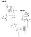
- FIG. 1A and Fig. 1B are views showing schematic structure of a drawing system and a measuring system for implementing the optical fiber fabrication method according to the present invention.
- Fig. 2A is a graph showing a relationship between chromatic dispersion and glass diameter (outside diameter of optical fiber), and Fig. 2B a graph showing a relation between cutoff wavelength and glass diameter (outside diameter of optical fiber).
- Fig. 3 is a flowchart for explaining the first embodiment of the optical fiber fabrication method according to the present invention.
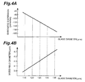
- Fig. 4A is a graph showing a relationship between chromatic dispersion and glass diameter (outside diameter of optical fiber), and Fig. 4B a graph showing a relation between mode field diameter and glass diameter (outside diameter of optical fiber).
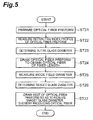
- Fig. 5 is a flowchart for explaining the second embodiment of the optical fiber fabrication method according to the present invention.
- FIG. 1A is a view showing the schematic structure of the drawing system for implementing the optical fiber fabrication method according to the present invention.
- an optical fiber preform 1 is fixed to a preform feeder 12 and is introduced into the interior of heating furnace 11 by the preform feeder 12. Then the heating furnace 11 heats and melts the lower part of the optical fiber preform 1. A bared optical fiber drawn from the lower part of the optical fiber preform 1 thus melted is pulled out of the lower part of the heating furnace 11 to the outside.
- the glass diameter d of this bared optical fiber is measured by an outside diameter gauge 13 and the surface of the fiber is coated with a resin by a resin coating unit 14.
- the resin coating unit 14 coats the surface of the bared optical fiber with an ultraviolet-curing resin through a primary coating die, and this ultraviolet-curing resin is once cured by irradiation with ultraviolet light.
- the resin surface of the coating on the bared optical fiber is further coated with the ultraviolet-curing resin through a secondary coating die, and this ultraviolet-curing resin coating is cured by irradiation with ultraviolet light, thereby obtaining a coated optical fiber 2.
- this coated optical fiber 2 is guided via capstan 16 and rollers 17 to 19 in order, to be wound up on a bobbin 20.
- the information about the glass diameter d of the bared optical fiber, measured by the outside diameter gauge 13, is supplied to a control unit 21.
- This control unit 21 controls each of the heating temperature (drawing temperature) of the optical fiber preform 1 by the heating furnace 11, the rotational speed of the capstan 16 (i.e., the drawing rate of the coated optical fiber 2), and the feed rate of the optical fiber preform 1 by the preform feeder 12.
- the control unit 21 controls the set feed rate Vf1 of the optical fiber preform 1 so as to satisfy Eq (1) below.
- Vf1 v1 ⁇ d 2 /D 2
- Fig. 2A is a graph showing the relationship between chromatic dispersion and glass diameter (outside diameter of the bared optical fiber), and Fig. 2B a graph showing the relationship between cutoff wavelength and glass diameter (outside diameter of the bared optical fiber).
- the cutoff wavelength also varies and the chromatic dispersion also varies. Namely, a difference between an actual cutoff wavelength measured and a target cutoff wavelength corresponds to a difference between actual chromatic dispersion and target chromatic dispersion. Therefore, the optical fiber fabrication method according to the first embodiment is arranged to adjust the glass diameter, based on the difference between the actual cutoff wavelength measured and the target cutoff wavelength, thereby correcting the actual chromatic dispersion to the target chromatic dispersion.
- Fig. 3 is a flowchart for explaining the optical fiber fabrication method according to the first embodiment.
- the optical fiber fabrication method according to the first embodiment is carried out by the drawing system and measuring system as shown in Fig. 1A and Fig. 1B.
- the first step is to prepare the optical fiber preform 1 whose refractive index profile is uniform in the longitudinal direction (step ST11), and the refractive index profile of this optical fiber preform 1 is measured by the preform analyzer (step ST12). Based on the result of this measurement and designed values of the preform structure, a glass diameter of the bared optical fiber is determined for fabrication of the coated optical fiber 2 having objective chromatic dispersion at a predetermined wavelength (e.g., 1.55 ⁇ m). This glass diameter determined is used as an initial glass diameter (step ST13).
- a predetermined wavelength e.g., 1.55 ⁇ m
- the optical fiber preform 1 is fixed to the preform feeder 12 and then the optical fiber preform 1 is guided into the heating furnace 11 by the preform feeder 12. This results in heating and melting the lower end of the optical fiber preform 1.
- the control unit 21 controls the outside diameter so that the glass diameter of the resultant bared optical fiber becomes the initial glass diameter.
- a portion (an optical fiber 2a of a fixed length to be measured) is cut out of the coated optical fiber 2 obtained after the start of drawing (step ST14), and the measuring system 210 shown in Fig. 1B measures the cutoff wavelength of this optical fiber 2a to be measured (step ST15).
- the optical fiber 2a to be measured has a length enough to measure the cutoff wavelength, which is specifically about 1 m to 10 m.
- the control unit 21 compares this measured cutoff wavelength with the target cutoff wavelength and corrects the glass diameter of the bared optical fiber for production of the coated optical fiber 2 having the objective chromatic dispersion at the predetermined wavelength, based on the result of the comparison.
- This corrected glass diameter is used as a target glass diameter (step ST16).
- step ST17 the rest of the optical fiber preform 1 is drawn so that the glass diameter of the resultant bared optical fiber becomes the target glass diameter, thereby fabricating the optical fiber with the desired optical characteristic (coated optical fiber 2) (step ST17).
- the initial glass diameter may also be employed as the target glass diameter as it is.
- the initial glass diameter do is employed as the target glass diameter d 1 as it is.
- the target glass diameter d 1 is determined by foregoing Eq (2).
- the method may also be arranged in such a manner that steps ST14 to ST16 are repeatedly carried out while the glass diameter is renewed until the difference between the cutoff wavelength measured at step ST15 and the target cutoff wavelength falls within the fixed range. This permits the target glass diameter to be set closer to the glass diameter of the fiber with the target cutoff wavelength more accurately.
- the set feed speed Vf1 of the optical fiber preform 1 is determined based on above Eq (1), on-line measurement is carried out to measure the glass diameter d of the coated optical fiber 2 by the outside diameter gauge 13, and the rotational speed of the capstan 16 is controlled based on this glass diameter d, which makes it feasible to maintain the glass diameter d of the bared optical fiber constant.
- These controls are carried out by the control unit 21.
- the cutoff wavelength is measured in the optical fiber with the fixed length obtained after the drawing start (the optical fiber 2a to be measured), the corrected target glass diameter is determined based on the measurement result, and the rest of the optical fiber preform 1 is drawn to fabricate the coated optical fiber 2 while the outside diameter is controlled so that the glass diameter becomes the target glass diameter.
- the optical fiber fabrication method is suitable for the fabrication of dispersion compensating optical fibers whose chromatic dispersion characteristic sensitively varies according to variation of glass diameter.
- Fig. 4A is a graph showing the relationship between chromatic dispersion and glass diameter (outside diameter of the bared optical fiber), and Fig. 4B a graph showing the relationship between mode field diameter and glass diameter (outside diameter of the bared optical fiber).
- the mode field diameter also varies and the chromatic dispersion also varies. Namely, a difference between an actual mode field diameter measured and a target mode field diameter corresponds to a difference between actual chromatic dispersion and target chromatic dispersion. Therefore, the second embodiment is arranged to adjust the glass diameter, based on the difference between the actual mode field diameter measured and the target mode field diameter, thereby correcting the actual chromatic dispersion to the target chromatic dispersion.
- Fig. 5 is a flowchart for explaining the optical fiber fabrication method according to the second embodiment.
- the optical fiber fabrication method according to the second embodiment is also carried out by the drawing system and measuring system as shown in Fig. 1A and Fig. 1B, as in the first embodiment.
- the first step is to prepare the optical fiber preform 1 whose refractive index profile is uniform in the longitudinal direction (step ST21), and the refractive index profile of this optical fiber preform 1 is measured by the preform analyzer (step ST22). Based on the result of this measurement and designed values of the preform structure, a glass diameter of the bared optical fiber is determined for fabrication of the coated optical fiber 2 having objective chromatic dispersion at a predetermined wavelength (e.g., 1.55 ⁇ m). This glass diameter determined is used as an initial glass diameter (step ST23).
- a predetermined wavelength e.g., 1.55 ⁇ m
- the optical fiber preform 1 is fixed to the preform feeder 12 and then the optical fiber preform 1 is guided into the heating furnace 11 by the preform feeder 12. This results in heating and melting the lower end of the optical fiber preform 1.
- the control unit 21 controls the outside diameter so that the glass diameter of the resultant bared optical fiber becomes the initial glass diameter.
- a portion (the optical fiber 2a to be measured) is cut out of the coated optical fiber 2 obtained after the start of drawing (step ST24), and the measuring system 210 shown in Fig. 1B measures the mode field diameter of this optical fiber 2a to be measured (step ST25).
- the optical fiber 2a to be measured has a length enough to measure the mode field diameter, which is specifically about 1 m to 10 m.
- the control unit 21 compares this measured mode field diameter with the target mode field diameter and corrects the glass diameter of the bared optical fiber for fabrication of the coated optical fiber 2 having the objective chromatic dispersion at the predetermined wavelength, based on the result of the comparison.
- This corrected glass diameter is used as a target glass diameter (step ST26).
- the target glass diameter d 1 is given by Eq (4) below.
- d 1 d 0 ⁇ M 1 /M 0
- step ST27 the rest of the optical fiber preform 1 is drawn so that the glass diameter of the resultant bared optical fiber becomes the target glass diameter, thereby fabricating the coated optical fiber 2 with the desired optical characteristic (step ST27).
- the initial glass diameter may also be employed as the target glass diameter as it is.
- the initial glass diameter d 0 is employed as the target glass diameter d 1 as it is.
- the target glass diameter d 1 is determined by foregoing Eq (4).
- the method may also be arranged in such a manner that steps ST24 to ST26 are repeatedly carried out while the glass diameter is renewed until the difference between the mode field diameter measured at step ST25 and the target mode field diameter falls within the fixed range. This permits the target glass diameter to be set closer to the glass diameter of the fiber with the target mode field diameter more accurately.
- the set feed speed Vf1 of the optical fiber preform 1 is determined based on above Eq (1), on-line measurement is carried out to measure the glass diameter d of the optical fiber 2 by the outside diameter gauge 13, and the rotational speed of the capstan 16 is controlled based on this glass diameter d, which makes it feasible to maintain the glass diameter d of the bared optical fiber constant.
- These controls are carried out by the control unit 21.
- the mode field diameter is measured in the optical fiber with the fixed length obtained after the drawing start (the optical fiber 2a to be measured), the corrected target glass diameter is determined based on the measurement result, and the rest of the optical fiber preform 1 is drawn to fabricate the coated optical fiber 2 while the outside diameter is controlled so that the glass diameter becomes the target glass diameter.
- the optical fiber fabrication method is suitable for the fabrication of dispersion compensating optical fibers whose chromatic dispersion characteristic sensitively varies according to variation of glass diameter.
- the target glass diameter for yielding the objective chromatic dispersion characteristic is determined based on the cutoff wavelength or the mode field diameter measured, and the rest of the optical fiber preform is drawn while the outside diameter is controlled to the target glass diameter thus determined. Accordingly, the optical fiber having the objective chromatic dispersion characteristic is obtained readily even if the processing accuracy of the optical fiber preform is poor or even if the measurement accuracy of refractive index profile of the optical fiber preform by the preform analyzer is poor.
- the present invention is suitably applicable to the fabrication of dispersion compensating optical fibers which sensitively vary the chromatic dispersion characteristic according to variation of the glass diameter (outside diameter of optical fiber).
Landscapes
- Chemical & Material Sciences (AREA)
- Engineering & Computer Science (AREA)
- Materials Engineering (AREA)
- Geochemistry & Mineralogy (AREA)
- Manufacturing & Machinery (AREA)
- General Life Sciences & Earth Sciences (AREA)
- Life Sciences & Earth Sciences (AREA)
- Organic Chemistry (AREA)
- Physics & Mathematics (AREA)
- General Physics & Mathematics (AREA)
- Optics & Photonics (AREA)
- Manufacture, Treatment Of Glass Fibers (AREA)
- Glass Compositions (AREA)
Abstract
Description
Claims (2)
- An optical fiber fabrication method of fabricating an optical fiber with a desired optical characteristic by drawing an optical fiber preform to produce an optical fiber, comprising the steps of:measuring a cutoff wavelength in an optical fiber with a fixed length which is obtained by drawing a part of said optical fiber preform;determining a target glass diameter for yielding an objective chromatic dispersion characteristic, based on said cutoff wavelength measured; anddrawing the rest of said optical fiber preform while controlling an outside diameter to said target glass diameter determined.
- An optical fiber fabrication method of fabricating an optical fiber with a desired optical characteristic by drawing an optical fiber preform, comprising the steps of:measuring a mode field diameter in an optical fiber with a fixed length which is obtained by drawing a portion of said optical fiber preform;determining a target glass diameter for yielding an objective chromatic dispersion characteristic, based on said mode field diameter measured; anddrawing the rest of said optical fiber preform while controlling an outside diameter to said target glass diameter determined.
Applications Claiming Priority (3)
| Application Number | Priority Date | Filing Date | Title |
|---|---|---|---|
| JP2000024225A JP3438775B2 (en) | 2000-02-01 | 2000-02-01 | Optical fiber manufacturing method |
| JP2000024225 | 2000-02-01 | ||
| PCT/JP2001/000715 WO2001056940A1 (en) | 2000-02-01 | 2001-02-01 | Method of manufacturing optical fiber |
Publications (2)
| Publication Number | Publication Date |
|---|---|
| EP1184347A1 true EP1184347A1 (en) | 2002-03-06 |
| EP1184347A4 EP1184347A4 (en) | 2006-07-19 |
Family
ID=18550251
Family Applications (1)
| Application Number | Title | Priority Date | Filing Date |
|---|---|---|---|
| EP01902725A Withdrawn EP1184347A4 (en) | 2000-02-01 | 2001-02-01 | PROCESS FOR PRODUCING OPTICAL FIBER |
Country Status (8)
| Country | Link |
|---|---|
| US (1) | US6502429B1 (en) |
| EP (1) | EP1184347A4 (en) |
| JP (1) | JP3438775B2 (en) |
| KR (1) | KR100750076B1 (en) |
| CN (1) | CN1192000C (en) |
| AU (2) | AU3056101A (en) |
| TW (1) | TW464771B (en) |
| WO (1) | WO2001056940A1 (en) |
Families Citing this family (10)
| Publication number | Priority date | Publication date | Assignee | Title |
|---|---|---|---|---|
| FR2809386B1 (en) * | 2000-05-25 | 2003-01-17 | Cit Alcatel | METHOD FOR MANUFACTURING OPTICAL FIBER WITH CONTROL OF TRANSMISSION CHARACTERISTICS |
| US6995900B2 (en) * | 2003-01-21 | 2006-02-07 | Jds Uniphase Corporation | Method of making a short-pass fiber with controlled cut-off wavelength |
| KR100492964B1 (en) * | 2002-07-29 | 2005-06-07 | 삼성전자주식회사 | Apparatus for drawing optical fiber and method for controlling optical fiber preform feeding speed |
| CN1331654C (en) * | 2004-12-31 | 2007-08-15 | 中国科学院西安光学精密机械研究所 | Drawing equipment for polymer photonic crystal fiber preform |
| KR100808354B1 (en) * | 2006-08-17 | 2008-02-27 | 엘에스전선 주식회사 | Single mode optical fiber with reduced polarization mode dispersion and manufacturing method thereof |
| JP5704395B2 (en) * | 2010-03-29 | 2015-04-22 | 日本電気硝子株式会社 | Glass roll package |
| TWI461768B (en) | 2012-11-01 | 2014-11-21 | Univ Nat Sun Yat Sen | A method for manufacturing an optical fiber and the optical fiber thereof |
| US9442007B2 (en) * | 2013-05-06 | 2016-09-13 | Phoseon Technology, Inc. | Method and system for monitoring ultraviolet light for a fiber cure system |
| CN104973774B (en) * | 2014-04-02 | 2019-08-30 | 住友电气工业株式会社 | Optical fiber manufacturing method and manufacturing device |
| JP7012411B2 (en) * | 2018-03-30 | 2022-02-14 | 古河電気工業株式会社 | A method for stretching a core base material, a method for manufacturing an optical fiber base material, and a method for manufacturing an optical fiber. |
Family Cites Families (8)
| Publication number | Priority date | Publication date | Assignee | Title |
|---|---|---|---|---|
| JPH0688806B2 (en) * | 1986-06-03 | 1994-11-09 | 日立電線株式会社 | Low loss single mode optical fiber manufacturing method. |
| JPH0627012B2 (en) * | 1986-06-03 | 1994-04-13 | 日立電線株式会社 | Low loss single mode optical fiber manufacturing method. |
| US5175785A (en) * | 1991-05-02 | 1992-12-29 | Ensign-Bickford Optical Technologies, Inc. | Optical waveguides having reduced bending loss and method of making the same |
| US5361319A (en) * | 1992-02-04 | 1994-11-01 | Corning Incorporated | Dispersion compensating devices and systems |
| KR950000588A (en) * | 1993-06-18 | 1995-01-03 | 쿠라우찌 노리타카 | Manufacturing method of single mode optical fiber base material |
| US5925163A (en) * | 1993-12-27 | 1999-07-20 | Corning, Inc. | Method of making an optical fiber with an axially decreasing group velocity dispersion |
| JPH08217481A (en) | 1995-02-17 | 1996-08-27 | Fujikura Ltd | Optical fiber manufacturing method and drawing apparatus |
| US6250112B1 (en) * | 1999-06-03 | 2001-06-26 | Corning Incorporated | Method of controlling an extrusion of glass to make an optical fiber |
-
2000
- 2000-02-01 JP JP2000024225A patent/JP3438775B2/en not_active Expired - Fee Related
-
2001
- 2001-02-01 AU AU3056101A patent/AU3056101A/en not_active Withdrawn
- 2001-02-01 CN CNB018025765A patent/CN1192000C/en not_active Expired - Fee Related
- 2001-02-01 AU AU2001230561A patent/AU2001230561B2/en not_active Ceased
- 2001-02-01 US US09/937,774 patent/US6502429B1/en not_active Expired - Lifetime
- 2001-02-01 KR KR1020027009868A patent/KR100750076B1/en not_active Expired - Fee Related
- 2001-02-01 WO PCT/JP2001/000715 patent/WO2001056940A1/en not_active Ceased
- 2001-02-01 TW TW090102012A patent/TW464771B/en not_active IP Right Cessation
- 2001-02-01 EP EP01902725A patent/EP1184347A4/en not_active Withdrawn
Also Published As
| Publication number | Publication date |
|---|---|
| CN1388795A (en) | 2003-01-01 |
| EP1184347A4 (en) | 2006-07-19 |
| CN1192000C (en) | 2005-03-09 |
| US20030005727A1 (en) | 2003-01-09 |
| US6502429B1 (en) | 2003-01-07 |
| AU2001230561B2 (en) | 2005-02-17 |
| KR20020084108A (en) | 2002-11-04 |
| WO2001056940A1 (en) | 2001-08-09 |
| AU3056101A (en) | 2001-08-14 |
| JP2001215344A (en) | 2001-08-10 |
| JP3438775B2 (en) | 2003-08-18 |
| TW464771B (en) | 2001-11-21 |
| KR100750076B1 (en) | 2007-08-21 |
Similar Documents
| Publication | Publication Date | Title |
|---|---|---|
| US6502429B1 (en) | Optical fiber fabrication method | |
| US20090052853A1 (en) | Holey fiber and method of manufacturing the same | |
| US7197898B2 (en) | Robust diameter-controlled optical fiber during optical fiber drawing process | |
| US6853784B2 (en) | Optical fiber | |
| US6473548B2 (en) | Multiple fiber optical cable and method of manufacturing multiple fiber optical cable | |
| EP1564570A1 (en) | Optical fiber having reduced residual stress discontinuity | |
| EP0989422A2 (en) | Tapered optical fiber devices with variable index coatings for modifying guide properties of the fundamental mode | |
| US4902327A (en) | Monitoring fiber bend loss characteristics during manufacture | |
| US6371394B1 (en) | Method for winding a fibre element having different longitudinal portions | |
| CN1931757B (en) | Optical fiber drawing process and control new method | |
| US6502428B1 (en) | Manufacturing method of an optical fiber | |
| JP4398634B2 (en) | Optical fiber manufacturing method | |
| JP2001220167A (en) | Optical fiber manufacturing method | |
| EP0687929B1 (en) | Method for manufacturing optical fiber coupler | |
| US20010010162A1 (en) | Method of making optical fiber | |
| JP2001163632A (en) | Optical fiber manufacturing method and optical fiber manufacturing apparatus | |
| HK1051524A (en) | Method of manufacturing optical fiber | |
| US20250214882A1 (en) | Method for producing optical fiber | |
| JPH10182181A (en) | Optical fiber manufacturing method | |
| US20040016264A1 (en) | Apparatus for drawing an optical fiber and method for controlling feed speed of an optical fiber preform | |
| KR100438348B1 (en) | Optical fiber having different refractive index directed to the length and to be fitted manufacturing method | |
| CN1325827A (en) | Method for drawing optical fibers | |
| JP2007063093A (en) | Optical fiber manufacturing method and manufacturing apparatus | |
| Hooper | Effects of draw conditions on toss in multimode optical fibers | |
| JPH02289441A (en) | Production of optical fiber |
Legal Events
| Date | Code | Title | Description |
|---|---|---|---|
| PUAI | Public reference made under article 153(3) epc to a published international application that has entered the european phase |
Free format text: ORIGINAL CODE: 0009012 |
|
| 17P | Request for examination filed |
Effective date: 20011009 |
|
| AK | Designated contracting states |
Kind code of ref document: A1 Designated state(s): AT BE CH CY DE DK ES FI FR GB GR IE IT LI LU MC NL PT SE TR |
|
| RBV | Designated contracting states (corrected) |
Designated state(s): GB SE |
|
| REG | Reference to a national code |
Ref country code: DE Ref legal event code: 8566 |
|
| A4 | Supplementary search report drawn up and despatched |
Effective date: 20060621 |
|
| GRAP | Despatch of communication of intention to grant a patent |
Free format text: ORIGINAL CODE: EPIDOSNIGR1 |
|
| STAA | Information on the status of an ep patent application or granted ep patent |
Free format text: STATUS: THE APPLICATION IS DEEMED TO BE WITHDRAWN |
|
| 18D | Application deemed to be withdrawn |
Effective date: 20100324 |