EP1184254A2 - Lane keeping assistance system and method for automotive vehicle - Google Patents
Lane keeping assistance system and method for automotive vehicle Download PDFInfo
- Publication number
- EP1184254A2 EP1184254A2 EP01306044A EP01306044A EP1184254A2 EP 1184254 A2 EP1184254 A2 EP 1184254A2 EP 01306044 A EP01306044 A EP 01306044A EP 01306044 A EP01306044 A EP 01306044A EP 1184254 A2 EP1184254 A2 EP 1184254A2
- Authority
- EP
- European Patent Office
- Prior art keywords
- steering
- value
- control current
- fstr
- filter
- Prior art date
- Legal status (The legal status is an assumption and is not a legal conclusion. Google has not performed a legal analysis and makes no representation as to the accuracy of the status listed.)
- Granted
Links
- 238000000034 method Methods 0.000 title claims abstract description 27
- 238000001914 filtration Methods 0.000 claims description 10
- 238000006073 displacement reaction Methods 0.000 claims 3
- 238000009826 distribution Methods 0.000 description 9
- 238000012545 processing Methods 0.000 description 4
- 230000009471 action Effects 0.000 description 3
- 230000008859 change Effects 0.000 description 3
- 230000008569 process Effects 0.000 description 3
- 230000005540 biological transmission Effects 0.000 description 2
- 238000011161 development Methods 0.000 description 2
- 230000007246 mechanism Effects 0.000 description 2
- 238000011946 reduction process Methods 0.000 description 2
- 230000004044 response Effects 0.000 description 2
- 239000000853 adhesive Substances 0.000 description 1
- 230000001070 adhesive effect Effects 0.000 description 1
- 230000008901 benefit Effects 0.000 description 1
- 238000012937 correction Methods 0.000 description 1
- 230000001419 dependent effect Effects 0.000 description 1
- 238000001514 detection method Methods 0.000 description 1
- 239000000284 extract Substances 0.000 description 1
- 230000010354 integration Effects 0.000 description 1
- 238000012986 modification Methods 0.000 description 1
- 230000004048 modification Effects 0.000 description 1
Images




Classifications
-
- B—PERFORMING OPERATIONS; TRANSPORTING
- B62—LAND VEHICLES FOR TRAVELLING OTHERWISE THAN ON RAILS
- B62D—MOTOR VEHICLES; TRAILERS
- B62D15/00—Steering not otherwise provided for
- B62D15/02—Steering position indicators ; Steering position determination; Steering aids
- B62D15/025—Active steering aids, e.g. helping the driver by actively influencing the steering system after environment evaluation
-
- B—PERFORMING OPERATIONS; TRANSPORTING
- B62—LAND VEHICLES FOR TRAVELLING OTHERWISE THAN ON RAILS
- B62D—MOTOR VEHICLES; TRAILERS
- B62D1/00—Steering controls, i.e. means for initiating a change of direction of the vehicle
- B62D1/24—Steering controls, i.e. means for initiating a change of direction of the vehicle not vehicle-mounted
- B62D1/28—Steering controls, i.e. means for initiating a change of direction of the vehicle not vehicle-mounted non-mechanical, e.g. following a line or other known markers
- B62D1/286—Systems for interrupting non-mechanical steering due to driver intervention
-
- B—PERFORMING OPERATIONS; TRANSPORTING
- B62—LAND VEHICLES FOR TRAVELLING OTHERWISE THAN ON RAILS
- B62D—MOTOR VEHICLES; TRAILERS
- B62D5/00—Power-assisted or power-driven steering
- B62D5/04—Power-assisted or power-driven steering electrical, e.g. using an electric servo-motor connected to, or forming part of, the steering gear
- B62D5/0457—Power-assisted or power-driven steering electrical, e.g. using an electric servo-motor connected to, or forming part of, the steering gear characterised by control features of the drive means as such
- B62D5/046—Controlling the motor
- B62D5/0463—Controlling the motor calculating assisting torque from the motor based on driver input
-
- B—PERFORMING OPERATIONS; TRANSPORTING
- B60—VEHICLES IN GENERAL
- B60T—VEHICLE BRAKE CONTROL SYSTEMS OR PARTS THEREOF; BRAKE CONTROL SYSTEMS OR PARTS THEREOF, IN GENERAL; ARRANGEMENT OF BRAKING ELEMENTS ON VEHICLES IN GENERAL; PORTABLE DEVICES FOR PREVENTING UNWANTED MOVEMENT OF VEHICLES; VEHICLE MODIFICATIONS TO FACILITATE COOLING OF BRAKES
- B60T2201/00—Particular use of vehicle brake systems; Special systems using also the brakes; Special software modules within the brake system controller
- B60T2201/08—Lane monitoring; Lane Keeping Systems
-
- B—PERFORMING OPERATIONS; TRANSPORTING
- B60—VEHICLES IN GENERAL
- B60T—VEHICLE BRAKE CONTROL SYSTEMS OR PARTS THEREOF; BRAKE CONTROL SYSTEMS OR PARTS THEREOF, IN GENERAL; ARRANGEMENT OF BRAKING ELEMENTS ON VEHICLES IN GENERAL; PORTABLE DEVICES FOR PREVENTING UNWANTED MOVEMENT OF VEHICLES; VEHICLE MODIFICATIONS TO FACILITATE COOLING OF BRAKES
- B60T2201/00—Particular use of vehicle brake systems; Special systems using also the brakes; Special software modules within the brake system controller
- B60T2201/08—Lane monitoring; Lane Keeping Systems
- B60T2201/087—Lane monitoring; Lane Keeping Systems using active steering actuation
Definitions
- the present invention relates generally to lane keeping assistance system (also called a lane following vehicle control system, but, hereinafter, referred to as lane keeping assistance system) and method for an automotive vehicle.
- the present invention relates more particularly to a technical field of the lane keeping assistance system and method in which automatic steering is carried out in such a way that traffic lane information is retrieved during a vehicular run and a steering torque is given to a steering force transmission system to follow the vehicle along a traffic lane at a forward direction of the vehicle or a driver's steering operation is supported to follow the traffic lane at the vehicular forward direction by providing a steering reaction torque is given to a vehicular steering force transmission system.
- the lane keeping assistance system has a region in which the vehicle can autonomously run along a white line and in which a development force by an actuator does not give an influence on a steering intervention. Hence, it is necessary to reduce the development force by a control quickly if a driver's steering intervention occurs.
- a torque sensor mounted on a column shift of a steering wheel can directly be used to determine the driver's steering intervention.
- a torque sensor is installed to detect a steering torque from a vehicular driver in order to switch between automatic steering and manual steering by an accurate trap of an intention of the vehicular driver.
- a control mode is shifted into an automatic steering mode.
- the control mode is shifted into the manual steering mode.
- a steering angle sensor (having a steering angular velocity output value) is used for a steering intervention determination.
- the steering angle sensor it is possible for the steering angle sensor to detect the driver's steering intervention only if a certain steering angular velocity occurs. Since the determination of the steering intervention in which no steering angular velocity is developed cannot be carried out, the determination of the steering intervention cannot be made in a case where a steady-state steering intervention (steering angular velocity ⁇ 0° s -1 (zero degree per second)) is carried out.
- the steering undesired feeling due to the steering interference is that, in a case of the manual steering intervention, a controlled output is caused to flow in a direction opposite to that caused by the driver's intervention and undesired feelings of steering wheel' s weight increase and of a sticky feeling can be given to the driver.
- an object of the present invention to provide lane keeping assistance system and method which can accurately determine such a steady-state steering intervention without generation of the steering intervention as described above and which can eliminate a large undesired feeling of steering due to a steering interference.
- a lane keeping assistance system for an automotive vehicle comprising: a traffic lane information detector (16) to detect an information related to a traffic lane on which the vehicle is about to run; a steering angle sensor (13) to detect a steering angle ( ⁇ ) of a steering wheel of the vehicle; a steering position changing section (8, 9) by which the steering wheel of the vehicle is enabled to be displaced independently of a manual steering operation through the steering wheel; a controlled steering target value setting section (15, Fig.
- a controlled steering target value ( ⁇ *) when a controlled steering to follow the traffic lane is carried out on the basis of at least the traffic lane related information detected by the traffic lane information detector and the steering angle detected by the steering angle sensor; a controlled steering command value setting section (15, Fig. 20) that outputs a control command value (Iout) in accordance with the controlled steering target value; a control command value filtering section (15, 22 of Fig.
- a manual steering intervention detector (15, 23 of Fig. 2, 67 and 69 of Fig. 6) to detect a steering intervention state to the controlled steering by the manual steering operation when the filtered control command value is in excess of a predetermined threshold control command value (Iout_lpf_th); and a controlled steering target value limiter (15, 24 and 25 of Fig. 2, and 70 and 71 of Fig. 6) to reduce the control command value (Iout) toward zero value to suppress the controlled steering target value toward a lower value direction including zero when the manual steering intervention is detected by the manual steering intervention detector.
- a predetermined filter threshold value fstr, fstr_low, fstr_mid, fstr_hi
- a method applicable to a lane keeping assistance system for an automotive vehicle in which a control current is outputted to a motor (8) of an automatic steering actuator coupled to a vehicular steering system (3, 7) to provide a steering force thereto to follow the vehicle along a traffic lane on a road located in a vehicular forwarding direction during a vehicular run in an automatic steering mode, the method comprising: detecting (20 of Fig. 2 and 60 of Fig. 9) the control current (Iout) to be outputted to the motor during the automatic steering mode; providing (22 of Fig. 2, 62 through 66 of Fig.
- a filter for the detected control current to pass only signal components of the detected control current whose frequencies are lower than a predetermined threshold frequency value of the filter to derive a filtered control current; determining (23 of Fig. 2 and 67 and 69 of Fig. 9) whether a manual steering intervention to the automatic steering occurs according to a magnitude of the filtered control current, the manual steering intervention being determined to occur depending on whether the magnitude of the filtered control current is in excess of a predetermined threshold current value of the filter; and reducing (24 and 25 of Fig. 2 and 70 and 71 of Fig.
- Fig. 1A is a whole system configuration view of a vehicular steering system to which a lane keeping assistance system for an automotive vehicle in a first preferred embodiment according to the present invention is applicable.
- Fig. 1B is a rough configuration of an automatic steering controller of the lane keeping assistance system in the first embodiment shown in Fig. 1.
- Fig. 2 is an operational flowchart executed by the automatic steering controller shown in Figs. 1A and 1B for a steering intervention determination procedure.
- Fig. 3 is a characteristic graph representing control current distributions during the execution of the lane keep control and during a driver's steering intervention.
- Fig. 4 is a characteristic graph representing a gain characteristic of a low-pass filter (LPF) used to detect a control current for the driver's steering intervention.
- LPF low-pass filter
- Fig. 5 is a characteristic graph representing a steering intervention determination region in a low-pass filter output current-versus-frequency relationship.
- Fig. 6 is an operational flowchart executed in automatic steering controller and representing a flow of a steering intervention determination procedure in a second preferred embodiment according to the present invention.
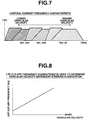
- Fig. 7 is a characteristic graph representing a control current-versus-frequency at a low velocity region, a middle velocity region, and a high velocity region.
- Fig. 8 is a characteristic graph representing a cut-off frequency characteristic of the low-pass filter with respect to a vehicular velocity.
- Fig. 9 is a characteristic graph representing the cut-off frequency characteristic of the low-pass filter used to detect a driver's steering intervention.
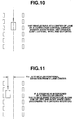
- Fig. 10 is an explanatory view representing a vehicular position with respect to a traffic lane during an input of an external disturbance to the vehicle.
- Fig. 11 is an explanatory view representing the vehicular position with respect to the traffic lane during the input of the driver's steering intervention.
- Fig. 12 is an operational flowchart representing an example of a main control routine on a lane keep control executed in the automatic steering controller.
- Fig. 1A shows a whole system configuration of a steering system of an automotive vehicle to which a lane keeping assistance system in a first preferred embodiment according to the present invention is applicable.
- a column shaft 2 is inserted into an inside of a steering column 1 and is supported by the steering column 1.
- a steering wheel 3 is disposed on an upper end of column shaft 2.
- a rack-and-pinion steering mechanism 6 is linked to steer left and right road wheels 4 and 5 at a lower end of column shaft 2.
- An assistance actuator 7 (or,so-called, automatic steering actuator) to provide an auxiliary steering torque is disposed at an intermediate position of column shaft 2.
- Assistance actuator 7 includes: an electric motor 8; an electromagnetic clutch 9 disposed on a motor axle; a drive gear 10 rotationally driven by motor 8 via electromagnetic clutch 9; and a worm-gear-to-speed-reduction mechanism having a driven gear 12 meshed with drive gear 10.
- a steering angle sensor 13 to detect a rotational angle of column shaft 2 is disposed on a position of column shaft 2 placed in proximity to steering wheel 3.
- An angle sensor 14 to detect a rotational angle of driven gear 10 is disposed. Sensor output signals from steering angle sensor 13 and angle sensor 14 are inputted to an automatic steering controller 15.
- Automatic steering controller 15 receives a video signal from a CCD (Charge Coupled Device) camera 16 arranged to photograph a forward road zone in a vehicular forwarding direction and a vehicular velocity indicative signal from a vehicular velocity sensor 17 as well as the sensor output signals from the steering angle sensor 13 and angle sensor 14.
- CCD Charge Coupled Device
- automatic steering controller 15 outputs a control current via a motor drive circuit 15g to motor 8 and outputs a clutch or de-clutch command to electromagnetic clutch 9.
- an automatic steering controller 15 implements image processing of road images in the vehicular forwarding direction on the basis of the video signal from CCD camera 11, extracts and discriminates boundary lines of a forward traffic lane such as a white line (broken line form) or center (boundary) line (solid line form), and generates vehicular running state information of a host vehicle (host vehicle means the vehicle on which the lane keeping assistance system is mounted).
- host vehicle means the vehicle on which the lane keeping assistance system is mounted.
- both of a steering torque and a target steering angle needed to follow the host vehicle along the forward traffic lane are calculated.
- automatic steering controller 15 implements fundamental control of lane keeping assistance by outputting the control current to motor 8.
- Fig. 1B shows a basic internal structure of automatic steering controller 15.
- Automatic steering controller 15 includes: a CPU (Central Processing Unit, but also called Microprocessor unit) 15a; a V-RAM (Video Random Access Memory) 15b; a RAM (Random Access Memory) 15c; a ROM (Read Only Memory) 15d, an Input Port 15e, an Output Port 15f, motor drive circuit (PWM (Pulse Width Modulation) circuit) 15g, and a common bus.
- a CPU Central Processing Unit, but also called Microprocessor unit
- V-RAM Video Random Access Memory
- RAM Random Access Memory
- ROM Read Only Memory
- Input Port 15e an Input Port
- Output Port 15f an Output Port
- motor drive circuit PWM (Pulse Width Modulation) circuit) 15g
- PWM Pulse Width Modulation
- Fig. 2 is an operational flowchart representing a flow of a steering intervention procedure executed by automatic steering controller 15. Each step shown in Fig. 2 will be described below.
- controller 15 detects the control current outputted to motor 8 from controller 15 (via the motor drive circuit 15g).
- controller 15 retrieves the vehicular velocity from vehicular velocity sensor 17.
- controller 15 provides a low-pass filtering process to pass signal components of only a low frequency range for the detected control current at step 20 to calculate a filtered output current Iout_lpf.
- a cut-off frequency of the low-pass filter is a predetermined constant value
- another low-pass filter having a cut-off frequency variable characteristic such that as the vehicular velocity becomes higher the cut-off frequency is shifted toward a higher direction may be used since the vehicular velocity is retrieved at step 21.
- controller 21 determines whether the calculated filtered output current Iout_lpf is in excess of a steering intervention threshold current Iout_lpf_th.
- controller 15 determines whether the steering intervention is present and the routine goes to a step 24.
- controller 15 gradually reduces the output current to 0 [A]. It is noted that, basically, when the steering intervention is determined to be present, the steering control may be turned to off. However, since an abrupt (stepwise) change of a steering force results in a steering unmatched feeling to a vehicular driver, the output current is gradually reduced.
- controller 15 determines whether a time duration from a time at which the answer of Yes is determined at step 23 is elapsed by a set time duration t [seconds]. Until the set time duration t is passed, the reduction process of the control current at step 24 is continued. It is noted that a return condition cannot be determined from the output current since the output current is already reduced and a time management is used to determine an automatic return.
- control current to make the host vehicle follow the traffic lane of the vehicular forwarding road is outputted to motor 8 so that the vehicular run to follow the traffic lane without the driver's steering operation can be assured.
- controller 15 During the vehicular run in the automatic steering mode, controller 15 provides at step 22 in Fig. 2 the low-pass filtering process for the control current outputted to the motor 8 to calculate the filtered output current Iout_lpf. At step 23, if the filtered output current Iout_lpf is in excess of steering intervention output current threshold current Iout_lpf_th, controller 15 determines that the driver has intervened in the automatic steering and the routine goes to step 24. At step 24, the control current for motor 8 of assistance actuator 7 is gradually reduced.
- the control current distribution by a lane keep control indicates a high density in a proximity to a vehicular yaw resonance of 1 Hz but that by a steady-state steering intervention indicates a distribution at a frequency region lower than that in the case of the lane keep control since a steering velocity is extremely low in the steady-state steering intervention. It is noted that since the steering velocity occurs during the steering intervention at the proximity to the frequency of the lane keep control, it is possible to make the driver's intervention determination according to the steering velocity (steering angular velocity).
- the output control current is constantly held at a output current limier Ilmt like an adhesive so that the control current distribution is concentrated in a control current limit value region as denoted by oblique lines in Fig. 3.
- the low-pass filter (refer to Fig. 4) which has a cut-off frequency fstr of a boundary frequency of two control current distributions.
- this region of steering intervention determination corresponds to the control current limit value region denoted by the oblique lines in Fig. 3.
- controller 15 can determine that the driver performs the steady-state steering intervention.
- the control current is used to determine the driver's steering intervention and, during the driver's steering intervention determination, control mode is gradually transferred to a manual steering mode by the vehicular driver.
- the driver's steering intervention determination is based on the determination without use of the torque sensor to directly detect the driver's steering intervention or without use of the steering angle sensor to indirectly detect the driver's steering intervention, the steady state steering intervention which does not generate the steering angular velocity can accurately be determined and such a large difference in the unmatched feeling of steering due to a steering interference between the lane keep control and the manual steering intervention by the driver can be eliminated.
- Fig. 6 shows an operational flowchart representing a flow of the steering intervention determination procedure executed by automatic steering controller 15 in the second preferred embodiment.
- automatic steering controller 15 detects the control current outputted to motor 8.
- controller 15 retrieves the vehicular velocity.
- controller 15 selects one of low-pass filters having difference cut-off frequencies according to a magnitude of the vehicular velocity retrieved at step 61.
- the magnitude of the vehicular velocity is divided into three regions, i.e., a low vehicular velocity region, a middle vehicular velocity region, and a high vehicular velocity region.
- controller 15 executes the low-pass filtering procedure using the low vehicular velocity region low pass filter having the cut-off frequency fstr_low for the detected control current at step 60.
- controller 15 executes the low-pass filtering procedure using the middle vehicular velocity region low-pass filter having the cut-off frequency frst_mid for the detected control current at step 60.
- controller 15 executes the low-pass filtering procedure using the high vehicular velocity region low-pass filter having the cut-off frequency frst_hi for the detected control current at step 60.
- the filtered control current Iout_lpf is calculated from the low-pass filtered control current passed at any one of steps 63, 64, and 65.
- controller 15 determines if the filtered output current Iout_lpf calculated at step 66 is in excess of the steering intervention threshold current Iout_lpf_th. If No (Iout_lpf ⁇ Iout_lpf_th) at step 67, controller 15 determine that there is no steering intervention and the routine returns to step 60. If Yes at step 67, the routine goes to a step 68.
- controller 15 retrieves a camera image and detects a lateral deviation Ym of a vehicular running position from a center position of the host vehicle running traffic lane.
- controller 15 determines if an absolute value
- controller 15 reduces gradually the output current toward zero 0 [A]. It is noted that basically the control may be turned off during the steering intervention. However, the abrupt change results in the unmatched steering feeling and, therefore, the output current is gradually reduced.
- controller 15 determines if the time duration from the time at which the controller 15 determines Yes at step 69 has passed by the set time t [sec.]. Until the set time t, the reduction process of the output current at step 70 is continued. It is noted that the return condition is not determined from the output current since the output current is already reduced but is the automatic return according to the time management.
- controller 15 at step 62 selects one of the low-pass filters having mutually different cut-off frequencies according to the magnitude of the vehicular velocity (low vehicular velocity region, the middle vehicular velocity region, and the high vehicular velocity region).
- the low vehicular velocity region low-pass filter having the cut-off frequency fstr_low At the low vehicular velocity region, the low vehicular velocity region low-pass filter having the cut-off frequency fstr_mid is selected.
- the high vehicular velocity region low-pass filter having the cut-off frequency frst_hi is selected. Then, the low-pass filtering process is carried out for the detected control current at any one of steps 63, 64, and 65 and at step 66 the filtered output current Iout_lpf is calculated.
- a control response to follow the traffic lane is increased as a rise in the vehicular velocity so that the control current distribution during the lane keep control is shifted toward the higher frequency side.
- the control current distribution due to the driver's steering intervention is also shifted toward the higher frequency side as the vehicular velocity is increased.
- the boundary frequency of the two control current distribution during the driver's steering intervention and the lane keep control is the cut-off frequency.
- the boundary frequency is varied in such a way as the cut-off frequency fstr_low at the low vehicular velocity region, that fstr_mid at the middle vehicular velocity region, and that fstr_hi at the high vehicular velocity region.
- controller 15 determines that the driver (driver' steering operation) has intervened the automatic steering and the routine shown in Fig. 6 goes to step 70 at which controller 15 reduces gradually the control current for motor 8 of the assistance actuator.
- the control current is supplied to motor 8 so that the host vehicle runs on a center part of the traffic lane which indicates a target traffic lane in the lane keep control against the input of an external disturbance such as road surface cant, lateral wind, or so forth.
- the control current is supplied to motor 8 so that the host vehicle is maintained to run on the traffic lane that the vehicular driver intends in the same manner as the case of the external disturbance, during the steering input by the driver. Since this control current is adhered or held on the limit value due to the provision of the limiter in the output current, the determination of whether it is the external disturbance input time or the driver' s steering input time cannot be made only by the control current value.
- the host vehicle basically, runs on the center position of the traffic lane which is the target traffic lane (refer to Fig. 10). While, during the driver's steering input, the host vehicle runs on a position of the traffic lane which is deviated from the center position of the traffic lane toward one of the left and right white lines (lane markers) in order to avoid collision against a large-sized truck which is running on one of the adjacent traffic lanes or the adjacent lane (refer to Fig. 11).
- the low-pass filter (LPF) is used to pass therethrough only the signal components in the low frequency range to the control current
- a band pass filter which passes the signal components of a middle frequency range between the low frequency range lower than the lower cut-off frequency and the high frequency range higher than the upper cut-off frequency may be used.
- the present invention is applicable to the controller from which the steering torque is provided for the steering system during the automatic steering mode
- the present invention is also applicable to a controller from which a steering reaction force torque is provided thereto. In the latter case, such a control that as a magnitude of the intervention from the driver becomes larger, the steering reaction torque becomes smaller is carried out.
- Fig. 12 shows an operational flowchart representing an example of the lane keep control procedure executed by automatic steering controller 15 in each embodiment during the automatic steering mode.
- Fig. 12 is a main interrupt routine executed whenever a predetermined period of time, for example, 10 milliseconds has passed.
- controller 15 reads actual steering angle ⁇ detected by steering angle sensor 13, a vehicular velocity detection value V detected by vehicular velocity sensor 17, a yaw angle ⁇ , lateral deviation y, and a radius of curvature ⁇ of the extracted white line detected from CCD camera 16 and image processed by controller 15. Then, the routine goes to a step S2.
- controller 15 calculates a target steering angle ⁇ * using the following equation (1) on the basis of the yaw angle ⁇ , the vehicular lateral deviation y, and the radius of curvature ⁇ .
- ⁇ * Ka ⁇ ⁇ + Kb ⁇ y + Kc ⁇ ⁇
- Ka, Kb, and Kc denote preset control gains varied according to the vehicular velocity and target steering angle ⁇ * indicates a positive value when the steering direction is in a clockwise direction as viewed from the driver's position and a negative value when the steering direction is in a counter-clockwise direction as viewed from the driver's position.
- automatic steering controller 15 calculates the motor supply current Iout using the following equation (2) and performs PID (Proportional-Integration-Differential) control to make the actual steering angle ⁇ substantially equal to target steering angle ⁇ *. Then, the motor supply current, i.e., the output current from controller 15 to motor 8 is stored into a motor supply current memory location to update the corresponding contents of the motor supply current memory location.
- Iout Kvi(Kp + Ki/s + kd ⁇ s) ( ⁇ * - ⁇ )
- Kvi denotes a control gain to convert a voltage value into a current value
- Kp denotes a proportional gain
- Ki denotes an integration gain
- Kd denotes a differential gain
- controller 15 subtracts actual steering angle ⁇ to derive a deviation ⁇ ⁇ from both steering angle values, performs the PID calculation for the deviation ⁇ ⁇ to derive a target motor control voltage V*, and converts target motor control voltage V* into the corresponding current value by a multiplication of the target motor control voltage V* by control gain Kvi to calculate the motor supply current Iout to motor 8, and the series of these calculations are carried out in a feedback loop configuration of controller 15 itself, motor 8, and associated sensors 13, 14, 16, and 17, and, in this feedback loop configuration, controller 15 performs its equivalent calculations.
- automatic steering controller 15 determines whether the calculated motor supply current Iout is in excess of the current limit value Ilimit stored in a current limit value memory location. If lout ⁇ Ilimit at step S4, the routine goes to a step S6. If Iout > Ilimit at step S4, the routine goes to a step S5.
- automatic steering controller 15 assigns the current limit value Ilimit (Ilimit ⁇ lout) and stores this motor supply current Iout ( i.e., Ilimit) into the motor supply current memory location to update the corresponding contents and the routine goes to step S6.
- controller 15 outputs the motor supply current (control current) Iout stored in the motor supply current memory location which is pulse-width modulated in PWM (Pulse-Width Modulator) circuit 15g to motor 8 whose direction is in accordance with the present steering direction.
- PWM Pulse-Width Modulator
- Traffic lane information detecting means corresponds to CCD camera 16 and automatic steering controller 15.
- Steering angle detecting means corresponds to steering angle sensor 13 and is exemplified by United States Patent No. 6,155,106 issued on December 5, 2000.
- the CCD camera is exemplified by United States Patent No. 6,226,592 issued on May 1, 2001.
- a controlled steering target value corresponds to target steering angle ⁇ * described above.
- a control command value corresponds to the control current Iout (this corresponds to the motor supply current). It is also noted that angle sensor 14 shown in Fig.
- electromagnetic clutch 9 is in the clutched state in response to the clutch command from automatic steering controller 15 during the automatic steering mode, and the automatic steering corresponds to a controlled steering.
Landscapes
- Engineering & Computer Science (AREA)
- Chemical & Material Sciences (AREA)
- Combustion & Propulsion (AREA)
- Transportation (AREA)
- Mechanical Engineering (AREA)
- Steering Control In Accordance With Driving Conditions (AREA)
- Power Steering Mechanism (AREA)
- Feedback Control In General (AREA)
- Traffic Control Systems (AREA)
Abstract
Description
Claims (10)
- A lane keeping assistance system for an automotive vehicle, comprising:a traffic lane information detector (16) to detect information related to a traffic lane on which the vehicle is about to run;a steering angle sensor (13) to detect a steering angle () of a steering wheel of the vehicle;a steering position changing section (8, 9) by which the steering wheel of the vehicle is enabled to be displaced independently of a manual steering operation through the steering wheel;a controlled steering target value setting section (15, Fig. 12) that sets a controlled steering target value (*) when controlled steering to follow the traffic lane is carried out on the basis of at least the traffic lane related information detected by the traffic lane information detector and the steering angle detected by the steering angle sensor;a controlled steering command value setting section (15, Fig. 20) that outputs a control command value (Iout) in accordance with the controlled steering target value;a control command value filtering section (15, 22 of Fig. 2, and 62 through 66 of Fig. 6) that filters the control command value to pass only frequency components of the control command value lower than a predetermined filter threshold value (fstr, fstr_low, fstr_mid, and fstr_hi) to derive a filtered control command value (Iout_lpf_th) during execution of the controlled steering;a manual steering intervention detector (15, 23 of Fig. 2, 67 and 69 of Fig. 6) to detect a steering intervention state to the controlled steering by the manual steering operation when the filtered control command value is in excess of a predetermined threshold control command value (Iout_lpf_th); anda controlled steering target value limiter (15, 24 and 25 of Fig. 2, and 70 and 72 of Fig. 6) to reduce the control command value (Iout) toward zero value to suppress the controlled steering target value toward a lower value direction including zero when the manual steering intervention is detected by the manual steering intervention detector.
- A lane keeping assistance system for an automotive vehicle as claimed in claim 1, further comprising:wherein the predetermined threshold value varying section varies the predetermined threshold value of the filter thereof toward a higher frequency side (Fig. 8) as the detected vehicular velocity (V) becomes increased.a vehicular velocity detector (17) to detect a vehicular velocity (V) of the vehicle; anda predetermined threshold value varying section (15, Fig. 7) that varies the predetermined filter threshold value (fstr) when the control command value filtering section provides the filter for the control command value to pass only predetermined frequency components lower than the predetermined filter threshold value;
- A lane keeping assistance system for an automotive vehicle as claimed in claim 1 or claim 2, further comprising a lateral displacement detector (15) to detect lateral displacement (Ym) of the vehicle from a center position of the traffic lane on the basis of the traffic lane information from the traffic lane information detector (16), wherein the manual steering intervention detector (15) detects the steering intervention state by the manual steering operation when the filtered control command value is in excess of the predetermined threshold control command value and, in addition, a magnitude (|Ym|) of the detected lateral displacement is in excess of an external disturbance determination threshold value (Ym_th).
- A lane keeping assistance system for an automotive vehicle as claimed in claim 1, wherein the steering position changing section comprises an electric motor (8) and the control command value is a current (lout) to be supplied to the electric motor.
- A lane keeping assistance system for an automotive vehicle as claimed in claim 1, wherein the filter of the control command value filtering section comprises a low-pass filter and the predetermined filter threshold value is a cut-off frequency (fstr, fstr_low, fstr_mid, and fstr_hi) of the low-pass filter.
- A method applicable to a lane keeping assistance system for an automotive vehicle in which a control current is outputted to a motor (8) of an automatic steering actuator coupled to a vehicular steering system (3, 7) to provide a steering force thereto to follow the vehicle along a traffic lane on a road located in a vehicular forwarding direction during a vehicular run in an automatic steering mode, the method comprising:detecting (20 of Fig. 2 and 60 of Fig. 9) the control current to be outputted to the motor during the automatic steering mode;providing (22 of Fig. 2, 62 through 66 of Fig. 6) a filter for the detected control current to pass only signal components of the detected control current whose frequencies are lower than a predetermined threshold frequency value of the filter to derive a filtered control current;determining (23 of Fig. 2, 67 and 69 of Fig. 6) whether a manual steering intervention to the automatic steering occurs according to a magnitude of the filtered control current, the manual steering intervention being determined to occur depending on whether the magnitude of the filtered control current is in excess of a predetermined threshold current value of the filter; andreducing (24 and 25 of Fig. 2, 70 and 71 of Fig. 6) the control current outputted to the motor toward zero value when, at the manual steering intervention determining step, the manual steering intervention is determined to occur according to a result of determination that the magnitude of the filtered control current (Iout_lpf) is in excess of the predetermined threshold current value (Iout_lpf_th).
- A method applicable to a lane keeping assistance system for an automotive vehicle as claimed in claim 6, further comprising detecting (61 of Fig. 6) a vehicular velocity, wherein the predetermined threshold frequency value (fstr) is a cut-off frequency of the filter, the cut-off frequency being varied toward a higher frequency side as the detected vehicular velocity becomes higher (Fig. 7).
- A method applicable to a lane keeping assistance system for an automotive vehicle as claimed in claim 6, further comprising: detecting (61 of Fig. 6) a vehicular velocity (V), wherein the filter comprises a low vehicular velocity low-pass filter having a lowest cut-off frequency (fstr_low), a middle vehicular velocity low-pass filter having a second lowest cut-off frequency (fstr_mid), and a high vehicular velocity low-pass filter having a highest vehicular velocity cut-off frequency (fstr_hi), and wherein, at the filter providing step (62 through 66 of Fig. 6), one of the low-pass filters is selected according to a magnitude of the detected vehicular velocity and the filtered control current (Iout_lpf) is calculated.
- A method applicable to a lane keeping assistance system for an automotive vehicle as claimed in any one of the preceding claims 6 through 8, further comprising detecting (68 of Fig. 6) traffic lane related information and detecting a lateral deviation of a vehicular position from a center position of the traffic lane on the basis of the detected traffic lane related information, wherein, at the manual steering intervention determining step (67 and 69 of Fig. 6), the manual steering intervention is determined to occur when the filtered control current is in excess of the predetermined threshold current value and, in addition, when a magnitude (|Ym|) of the detected lateral deviation is in excess of an external disturbance determination threshold value (Ym_th).
- A method applicable to a lane keeping assistance system for an automotive vehicle as claimed in any one of the preceding claims 6 through 9, wherein, at the control current reducing step (24 and 25 of Fig. 2, 70 and 71 of Fig. 6), the control current (lout) is gradually reduced toward zero value.
Applications Claiming Priority (2)
| Application Number | Priority Date | Filing Date | Title |
|---|---|---|---|
| JP2000268218A JP3498910B2 (en) | 2000-09-05 | 2000-09-05 | Lane tracking controller |
| JP2000268218 | 2000-09-05 |
Publications (3)
| Publication Number | Publication Date |
|---|---|
| EP1184254A2 true EP1184254A2 (en) | 2002-03-06 |
| EP1184254A3 EP1184254A3 (en) | 2003-07-23 |
| EP1184254B1 EP1184254B1 (en) | 2005-11-23 |
Family
ID=18755024
Family Applications (1)
| Application Number | Title | Priority Date | Filing Date |
|---|---|---|---|
| EP01306044A Expired - Lifetime EP1184254B1 (en) | 2000-09-05 | 2001-07-13 | Lane keeping assistance system and method for automotive vehicle |
Country Status (4)
| Country | Link |
|---|---|
| US (1) | US6493619B2 (en) |
| EP (1) | EP1184254B1 (en) |
| JP (1) | JP3498910B2 (en) |
| DE (1) | DE60115169T2 (en) |
Cited By (13)
| Publication number | Priority date | Publication date | Assignee | Title |
|---|---|---|---|---|
| US6863150B1 (en) | 2003-09-25 | 2005-03-08 | Mitsubishi Denki Kabushiki Kaisha | Electric power steering control apparatus |
| FR2861359A1 (en) * | 2003-10-24 | 2005-04-29 | Mitsubishi Electric Corp | ELECTRIC POWER STEERING CONTROL APPARATUS |
| DE102004012144A1 (en) * | 2004-03-12 | 2005-09-29 | Audi Ag | Method for assisting a driver during steering of a motor vehicle comprises using a surroundings field value with respect to the direction and/or position of a the vehicle in relation to a track |
| EP1602553A3 (en) * | 2004-05-31 | 2006-01-11 | Toyota Jidosha Kabushiki Kaisha | Driving support system and method |
| WO2006081936A1 (en) * | 2005-02-02 | 2006-08-10 | Daimlerchrysler Ag | Method and device for carrying out an automatic steering intervention in particular for lane-keeping assistance |
| WO2007050407A1 (en) * | 2005-10-21 | 2007-05-03 | Deere & Company | Systems and methods for switching between autonomous and manual operation of a vehicle |
| CN102039928A (en) * | 2009-10-22 | 2011-05-04 | 通用汽车环球科技运作公司 | Systems and methods for driver intervention in an automatic steering system |
| ES2516568R1 (en) * | 2013-04-30 | 2014-12-09 | Universidad Politécnica de Madrid | EQUIPMENT TO AUTOMATICALLY CONTROL THE ADDRESS OF A VEHICLE. |
| EP2821319A4 (en) * | 2012-03-02 | 2016-03-09 | Toyota Motor Co Ltd | CONTROL DEVICE FOR VEHICLE |
| CN105564504A (en) * | 2014-11-04 | 2016-05-11 | 沃尔沃汽车公司 | Method and system for intelligent scaling of torque overlay intervention for semi-autonomous road vehicle steering systems |
| EP2985205A4 (en) * | 2013-04-08 | 2016-12-21 | Mitsubishi Electric Corp | DIRECTION CONTROL DEVICE AND METHOD |
| EP3393887A4 (en) * | 2015-12-22 | 2018-12-26 | Uber Technologies, Inc. | Integrated clutch steering system |
| EP3483021A4 (en) * | 2016-07-05 | 2019-07-24 | Nissan Motor Co., Ltd. | MOVEMENT CONTROL METHOD AND TRAVEL CONTROL DEVICE |
Families Citing this family (72)
| Publication number | Priority date | Publication date | Assignee | Title |
|---|---|---|---|---|
| JP3649119B2 (en) * | 2000-12-12 | 2005-05-18 | 日産自動車株式会社 | Lane Keep Assist Control Device |
| JP3783562B2 (en) * | 2000-12-28 | 2006-06-07 | 日産自動車株式会社 | Vehicle travel control device |
| JP3585874B2 (en) * | 2001-09-04 | 2004-11-04 | 本田技研工業株式会社 | Vehicle travel control device |
| EP1502246B1 (en) * | 2002-04-30 | 2006-08-02 | Robert Bosch Gmbh | Method and device for informing a driver or for reacting when the vehicle leaves a lane |
| US6842678B2 (en) * | 2002-08-20 | 2005-01-11 | Visteon Global Technologies, Inc. | Motor vehicle steering system |
| JP4005483B2 (en) * | 2002-11-20 | 2007-11-07 | 日産自動車株式会社 | Lane departure prevention device |
| JP3873919B2 (en) * | 2003-03-20 | 2007-01-31 | 日産自動車株式会社 | Lane departure prevention device |
| US6976555B2 (en) * | 2003-06-30 | 2005-12-20 | Visteon Global Technologies, Inc. | Motor vehicle steering system |
| JP2005041283A (en) * | 2003-07-24 | 2005-02-17 | Hitachi Unisia Automotive Ltd | Steering control device |
| US6988583B2 (en) * | 2003-10-30 | 2006-01-24 | Deere & Company | Electrical steering system for manned or unmanned operation |
| JP3979382B2 (en) * | 2003-12-03 | 2007-09-19 | 日産自動車株式会社 | Lane departure prevention device |
| JP4281543B2 (en) * | 2003-12-16 | 2009-06-17 | 日産自動車株式会社 | VEHICLE DRIVE OPERATION ASSISTANCE DEVICE AND VEHICLE HAVING VEHICLE DRIVE OPERATION ASSISTANCE DEVICE |
| JP4226455B2 (en) * | 2003-12-16 | 2009-02-18 | 日産自動車株式会社 | Driving intention estimation device, vehicle driving assistance device, and vehicle equipped with vehicle driving assistance device |
| US7349767B2 (en) * | 2003-12-16 | 2008-03-25 | Nissan Motor Co., Ltd. | Method and system for intention estimation and operation assistance |
| JP2005193788A (en) * | 2004-01-07 | 2005-07-21 | Suzuki Motor Corp | Electric power steering device for snow vehicles |
| JP4211686B2 (en) * | 2004-06-02 | 2009-01-21 | トヨタ自動車株式会社 | Vehicle steering assist device |
| JP2006117181A (en) * | 2004-10-25 | 2006-05-11 | Favess Co Ltd | Steering control device |
| DE102004057262A1 (en) * | 2004-11-26 | 2006-06-01 | Robert Bosch Gmbh | Method and device for driver protection with driver-independent steering torque overlay |
| US7236907B2 (en) * | 2004-12-22 | 2007-06-26 | Robert Bosch Gmbh | Steering angle sensor assembly with pulse width modulated output signal |
| DE102005009350A1 (en) * | 2005-03-01 | 2006-09-07 | Trw Automotive Gmbh | Method for controlling an electric power steering system |
| JP2006264623A (en) * | 2005-03-25 | 2006-10-05 | Mitsubishi Fuso Truck & Bus Corp | Lane maintenance support device |
| JP2006264624A (en) * | 2005-03-25 | 2006-10-05 | Daimler Chrysler Ag | Lane maintenance support device |
| FR2892085B1 (en) * | 2005-10-19 | 2007-11-23 | Koyo Steering Europ Soc Par Ac | METHOD FOR DETERMINING IN REAL TIME THE HOLDING OF A DRIVING WHEEL OF AN ELECTRIC POWER STEERING OF A MOTOR VEHICLE |
| AU2011213807B2 (en) * | 2005-10-21 | 2014-05-22 | Deere & Company | Systems and methods for switching between autonomous and manual operation of a vehicle |
| JP4645598B2 (en) * | 2006-05-23 | 2011-03-09 | 株式会社デンソー | Brake control device for vehicle |
| JP4632093B2 (en) * | 2006-06-07 | 2011-02-16 | 株式会社ジェイテクト | Vehicle steering system |
| JP4587050B2 (en) * | 2006-06-13 | 2010-11-24 | 株式会社ジェイテクト | Vehicle steering system |
| JP4449960B2 (en) * | 2006-08-22 | 2010-04-14 | トヨタ自動車株式会社 | Steering support device |
| WO2008072007A2 (en) * | 2006-12-11 | 2008-06-19 | Bae Systems Plc | Controlling an autonomous vehicle system |
| DE102007022184A1 (en) * | 2007-05-11 | 2008-11-13 | Robert Bosch Gmbh | Driver assistance device and method for its control |
| EP2017162B1 (en) * | 2007-07-19 | 2013-06-12 | Nissan Motor Co., Ltd. | In-lane running support system, automobile and in-lane running support method |
| JP5892482B2 (en) * | 2007-08-15 | 2016-03-23 | ボルボ テクノロジー コーポレイション | Driving control method and system for vehicle lane keeping assistance |
| JP4995029B2 (en) * | 2007-10-18 | 2012-08-08 | 富士重工業株式会社 | Vehicle driving support device |
| WO2009069196A1 (en) | 2007-11-27 | 2009-06-04 | Mitsubishi Electric Corporation | Steering control device |
| JP4532569B2 (en) * | 2008-01-21 | 2010-08-25 | 本田技研工業株式会社 | Vehicle driving support device |
| US8392064B2 (en) | 2008-05-27 | 2013-03-05 | The Board Of Trustees Of The Leland Stanford Junior University | Systems, methods and devices for adaptive steering control of automotive vehicles |
| US8244434B2 (en) * | 2008-06-17 | 2012-08-14 | Agco Corporation | Methods and system for automatic user-configurable steering parameter control |
| JP5267230B2 (en) * | 2009-03-10 | 2013-08-21 | 日産自動車株式会社 | Parking assistance device and parking assistance method |
| US9180908B2 (en) * | 2010-11-19 | 2015-11-10 | Magna Electronics Inc. | Lane keeping system and lane centering system |
| KR101814601B1 (en) * | 2010-12-09 | 2018-01-04 | 삼성전자주식회사 | System and method for safe taxi service |
| US8965633B2 (en) * | 2011-09-02 | 2015-02-24 | GM Global Technology Operations LLC | System and method for speed adaptive steering override detection during automated lane centering |
| US8954255B1 (en) | 2011-09-16 | 2015-02-10 | Robert J. Crawford | Automobile-speed control using terrain-based speed profile |
| US9340227B2 (en) * | 2012-08-14 | 2016-05-17 | Magna Electronics Inc. | Vehicle lane keep assist system |
| KR101978519B1 (en) * | 2012-12-26 | 2019-08-28 | 현대모비스 주식회사 | Cooperating System of Lane Keeping Assist System and Motor driven Power Streering and method thereof |
| US9733643B2 (en) * | 2013-12-20 | 2017-08-15 | Agjunction Llc | Hydraulic interrupter safety system and method |
| US9487235B2 (en) | 2014-04-10 | 2016-11-08 | Magna Electronics Inc. | Vehicle control system with adaptive wheel angle correction |
| WO2015174943A1 (en) | 2014-05-12 | 2015-11-19 | Kutluay Emir | A system for keeping and tracking lane |
| KR101621747B1 (en) * | 2014-12-15 | 2016-05-17 | 주식회사 만도 | Electric Steering Apparatus and Controlling Method of the Same |
| US10713506B2 (en) | 2014-12-18 | 2020-07-14 | Magna Electronics Inc. | Vehicle vision system with 3D registration for distance estimation |
| US9946940B2 (en) | 2014-12-18 | 2018-04-17 | Magna Electronics Inc. | Vehicle vision system with adaptive lane marker detection |
| US9499202B2 (en) * | 2015-04-15 | 2016-11-22 | Delphi Technologies, Inc. | Steering system and method for autonomous vehicles |
| US10449899B2 (en) | 2015-05-08 | 2019-10-22 | Magna Electronics Inc. | Vehicle vision system with road line sensing algorithm and lane departure warning |
| EP3702246B1 (en) * | 2015-05-26 | 2025-10-08 | Exonetik Inc. | Active steering system using magnetorheological fluid clutch apparatuses |
| US9796410B2 (en) | 2016-01-28 | 2017-10-24 | Denso Corporation | Motor controller |
| FR3048943B1 (en) * | 2016-03-16 | 2018-04-13 | Peugeot Citroen Automobiles Sa | ASSISTANCE SYSTEM, FUNCTION OF THE CONTRIBUTION OF THE DRIVER OF THE VEHICLE |
| US10513287B2 (en) * | 2016-06-06 | 2019-12-24 | Nsk Ltd. | Electric power steering apparatus |
| BR112019004582B1 (en) * | 2016-09-09 | 2023-12-26 | Nissan Motor Co., Ltd | DISPLACEMENT CONTROL METHOD AND APPARATUS FOR A VEHICLE |
| US10699305B2 (en) | 2016-11-21 | 2020-06-30 | Nio Usa, Inc. | Smart refill assistant for electric vehicles |
| JP2018103713A (en) * | 2016-12-26 | 2018-07-05 | トヨタ自動車株式会社 | Vehicle traveling control device and automatic driving control method |
| US10471829B2 (en) | 2017-01-16 | 2019-11-12 | Nio Usa, Inc. | Self-destruct zone and autonomous vehicle navigation |
| US10837790B2 (en) | 2017-08-01 | 2020-11-17 | Nio Usa, Inc. | Productive and accident-free driving modes for a vehicle |
| JP6795792B2 (en) * | 2017-09-28 | 2020-12-02 | トヨタ自動車株式会社 | Driving support device |
| US10635109B2 (en) | 2017-10-17 | 2020-04-28 | Nio Usa, Inc. | Vehicle path-planner monitor and controller |
| US10606274B2 (en) | 2017-10-30 | 2020-03-31 | Nio Usa, Inc. | Visual place recognition based self-localization for autonomous vehicles |
| US10935978B2 (en) | 2017-10-30 | 2021-03-02 | Nio Usa, Inc. | Vehicle self-localization using particle filters and visual odometry |
| WO2020130479A1 (en) * | 2018-12-19 | 2020-06-25 | 주식회사 만도 | Steering control apparatus, steering control method, and steering apparatus |
| EP3730384B1 (en) | 2019-04-24 | 2022-10-26 | Aptiv Technologies Limited | System and method for trajectory estimation |
| JP7095661B2 (en) * | 2019-07-15 | 2022-07-05 | トヨタ自動車株式会社 | Disturbance handling system for vehicles |
| US20220258795A1 (en) * | 2019-10-18 | 2022-08-18 | Nissan Motor Co., Ltd. | Overriding determination method for driving assist device, and driving assist device |
| CN111055846B (en) * | 2019-12-19 | 2021-09-07 | 浙江吉利汽车研究院有限公司 | Device and method for detecting hand-off of steering wheel |
| DE102021202740A1 (en) * | 2021-03-22 | 2022-09-22 | Continental Autonomous Mobility Germany GmbH | System and method for controlling an electromechanical steering system of a vehicle |
| CN114715256A (en) * | 2022-03-31 | 2022-07-08 | 同济大学 | An unmanned vehicle steering wheel control system for automatic switching between man and machine |
Family Cites Families (11)
| Publication number | Priority date | Publication date | Assignee | Title |
|---|---|---|---|---|
| US5208750A (en) | 1987-06-17 | 1993-05-04 | Nissan Motor Co., Ltd. | Control system for unmanned automotive vehicle |
| GB9317983D0 (en) | 1993-08-28 | 1993-10-13 | Lucas Ind Plc | A driver assistance system for a vehicle |
| JP3569587B2 (en) * | 1996-02-07 | 2004-09-22 | 本田技研工業株式会社 | Vehicle steering system |
| JP3622329B2 (en) * | 1996-03-08 | 2005-02-23 | スズキ株式会社 | Vehicle steering device |
| JP3311277B2 (en) * | 1997-09-05 | 2002-08-05 | 本田技研工業株式会社 | Automatic vehicle steering system |
| JP3280893B2 (en) * | 1997-09-13 | 2002-05-13 | 本田技研工業株式会社 | Vehicle steering control device |
| US6155106A (en) | 1997-10-29 | 2000-12-05 | Alps Electric Co., Inc. | Steering angle sensor unit |
| JP3246428B2 (en) * | 1997-12-25 | 2002-01-15 | 三菱自動車工業株式会社 | Lane departure prevention device |
| DE19943410B4 (en) * | 1998-09-11 | 2011-08-18 | Honda Giken Kogyo K.K. | Steering control system for a vehicle |
| JP3571234B2 (en) * | 1998-10-12 | 2004-09-29 | 本田技研工業株式会社 | Vehicle steering control device |
| US6226592B1 (en) | 1999-03-22 | 2001-05-01 | Veridian Erim International, Inc. | Method and apparatus for prompting a motor vehicle operator to remain within a lane |
-
2000
- 2000-09-05 JP JP2000268218A patent/JP3498910B2/en not_active Expired - Fee Related
-
2001
- 2001-07-13 DE DE60115169T patent/DE60115169T2/en not_active Expired - Fee Related
- 2001-07-13 EP EP01306044A patent/EP1184254B1/en not_active Expired - Lifetime
- 2001-08-16 US US09/930,168 patent/US6493619B2/en not_active Expired - Fee Related
Cited By (23)
| Publication number | Priority date | Publication date | Assignee | Title |
|---|---|---|---|---|
| US6863150B1 (en) | 2003-09-25 | 2005-03-08 | Mitsubishi Denki Kabushiki Kaisha | Electric power steering control apparatus |
| FR2861359A1 (en) * | 2003-10-24 | 2005-04-29 | Mitsubishi Electric Corp | ELECTRIC POWER STEERING CONTROL APPARATUS |
| DE102004012144B4 (en) * | 2004-03-12 | 2009-04-09 | Audi Ag | A method and apparatus for assisting a driver in steering the motor vehicle |
| DE102004012144A1 (en) * | 2004-03-12 | 2005-09-29 | Audi Ag | Method for assisting a driver during steering of a motor vehicle comprises using a surroundings field value with respect to the direction and/or position of a the vehicle in relation to a track |
| EP1602553A3 (en) * | 2004-05-31 | 2006-01-11 | Toyota Jidosha Kabushiki Kaisha | Driving support system and method |
| US7389167B2 (en) | 2004-05-31 | 2008-06-17 | Toyota Jidosha Kabushiki Kaisha | Driving support system and method |
| WO2006081936A1 (en) * | 2005-02-02 | 2006-08-10 | Daimlerchrysler Ag | Method and device for carrying out an automatic steering intervention in particular for lane-keeping assistance |
| US8020657B2 (en) | 2005-10-21 | 2011-09-20 | Deere & Company | Systems and methods for obstacle avoidance |
| US9043016B2 (en) | 2005-10-21 | 2015-05-26 | Deere & Company | Versatile robotic control module |
| WO2007050407A1 (en) * | 2005-10-21 | 2007-05-03 | Deere & Company | Systems and methods for switching between autonomous and manual operation of a vehicle |
| US8874300B2 (en) | 2005-10-21 | 2014-10-28 | Deere & Company | Systems and methods for obstacle avoidance |
| US7894951B2 (en) | 2005-10-21 | 2011-02-22 | Deere & Company | Systems and methods for switching between autonomous and manual operation of a vehicle |
| CN102039928A (en) * | 2009-10-22 | 2011-05-04 | 通用汽车环球科技运作公司 | Systems and methods for driver intervention in an automatic steering system |
| EP2821319A4 (en) * | 2012-03-02 | 2016-03-09 | Toyota Motor Co Ltd | CONTROL DEVICE FOR VEHICLE |
| EP2985205A4 (en) * | 2013-04-08 | 2016-12-21 | Mitsubishi Electric Corp | DIRECTION CONTROL DEVICE AND METHOD |
| ES2516568R1 (en) * | 2013-04-30 | 2014-12-09 | Universidad Politécnica de Madrid | EQUIPMENT TO AUTOMATICALLY CONTROL THE ADDRESS OF A VEHICLE. |
| CN105564504A (en) * | 2014-11-04 | 2016-05-11 | 沃尔沃汽车公司 | Method and system for intelligent scaling of torque overlay intervention for semi-autonomous road vehicle steering systems |
| EP3018040A1 (en) * | 2014-11-04 | 2016-05-11 | Volvo Car Corporation | Method and system for intelligent scaling of torque overlay intervention for semi-autonomous road vehicle steering systems |
| US9527527B2 (en) | 2014-11-04 | 2016-12-27 | Volvo Car Corporation | Method and system for intelligent scaling of torque overlay intervention for semi-autonomous road vehicle steering systems |
| CN105564504B (en) * | 2014-11-04 | 2019-07-12 | 沃尔沃汽车公司 | The method and system that the torque superposition of the intelligent semi-autonomous road vehicle steering system of scale is intervened |
| EP3393887A4 (en) * | 2015-12-22 | 2018-12-26 | Uber Technologies, Inc. | Integrated clutch steering system |
| EP3865374A1 (en) * | 2015-12-22 | 2021-08-18 | Uatc, Llc | Integrated clutch steering system |
| EP3483021A4 (en) * | 2016-07-05 | 2019-07-24 | Nissan Motor Co., Ltd. | MOVEMENT CONTROL METHOD AND TRAVEL CONTROL DEVICE |
Also Published As
| Publication number | Publication date |
|---|---|
| JP3498910B2 (en) | 2004-02-23 |
| US6493619B2 (en) | 2002-12-10 |
| JP2002067998A (en) | 2002-03-08 |
| EP1184254B1 (en) | 2005-11-23 |
| EP1184254A3 (en) | 2003-07-23 |
| DE60115169T2 (en) | 2006-08-03 |
| DE60115169D1 (en) | 2005-12-29 |
| US20020169531A1 (en) | 2002-11-14 |
Similar Documents
| Publication | Publication Date | Title |
|---|---|---|
| EP1184254B1 (en) | Lane keeping assistance system and method for automotive vehicle | |
| EP1170195B1 (en) | Lane following vehicle control | |
| US6542800B2 (en) | Lane following vehicle control | |
| US10649454B2 (en) | Autonomous vehicle | |
| EP2050653B1 (en) | Steering system | |
| EP3309044B1 (en) | Steering assist apparatus | |
| US9211911B2 (en) | Method for steering assistance during an emergency maneuver | |
| EP1394015B1 (en) | Electric power steering apparatus. | |
| US6212453B1 (en) | Vehicle steering control system | |
| US6256561B1 (en) | Vehicle steering control system | |
| US20100138112A1 (en) | Vehicle steering control device and method | |
| JP3775120B2 (en) | Lane tracking device | |
| US20250100613A1 (en) | Motor control device | |
| EP1211157B1 (en) | Electric power steering controller | |
| EP4431368A1 (en) | Motor control device | |
| JP7385764B2 (en) | Steer-by-wire steering system | |
| US12397852B2 (en) | Steering control apparatus | |
| JP3864892B2 (en) | Lane departure prevention device | |
| JP3409838B2 (en) | Vehicle steering system | |
| CN120187625A (en) | Motor control device | |
| JP4711758B2 (en) | Vehicle operation support device | |
| JP4648229B2 (en) | Vehicle operation support device | |
| US20240149942A1 (en) | Steer-by-wire type steering apparatus | |
| CN118103280A (en) | Motor control device | |
| JP4923565B2 (en) | Steering device |
Legal Events
| Date | Code | Title | Description |
|---|---|---|---|
| PUAI | Public reference made under article 153(3) epc to a published international application that has entered the european phase |
Free format text: ORIGINAL CODE: 0009012 |
|
| 17P | Request for examination filed |
Effective date: 20010813 |
|
| AK | Designated contracting states |
Kind code of ref document: A2 Designated state(s): AT BE CH CY DE DK ES FI FR GB GR IE IT LI LU MC NL PT SE TR |
|
| AX | Request for extension of the european patent |
Free format text: AL;LT;LV;MK;RO;SI |
|
| PUAL | Search report despatched |
Free format text: ORIGINAL CODE: 0009013 |
|
| AK | Designated contracting states |
Designated state(s): AT BE CH CY DE DK ES FI FR GB GR IE IT LI LU MC NL PT SE TR |
|
| AX | Request for extension of the european patent |
Extension state: AL LT LV MK RO SI |
|
| AKX | Designation fees paid |
Designated state(s): DE FR GB |
|
| GRAP | Despatch of communication of intention to grant a patent |
Free format text: ORIGINAL CODE: EPIDOSNIGR1 |
|
| GRAS | Grant fee paid |
Free format text: ORIGINAL CODE: EPIDOSNIGR3 |
|
| GRAA | (expected) grant |
Free format text: ORIGINAL CODE: 0009210 |
|
| AK | Designated contracting states |
Kind code of ref document: B1 Designated state(s): DE FR GB |
|
| REG | Reference to a national code |
Ref country code: GB Ref legal event code: FG4D |
|
| REF | Corresponds to: |
Ref document number: 60115169 Country of ref document: DE Date of ref document: 20051229 Kind code of ref document: P |
|
| ET | Fr: translation filed | ||
| PLBE | No opposition filed within time limit |
Free format text: ORIGINAL CODE: 0009261 |
|
| STAA | Information on the status of an ep patent application or granted ep patent |
Free format text: STATUS: NO OPPOSITION FILED WITHIN TIME LIMIT |
|
| 26N | No opposition filed |
Effective date: 20060824 |
|
| PGFP | Annual fee paid to national office [announced via postgrant information from national office to epo] |
Ref country code: FR Payment date: 20090710 Year of fee payment: 9 |
|
| PGFP | Annual fee paid to national office [announced via postgrant information from national office to epo] |
Ref country code: DE Payment date: 20090709 Year of fee payment: 9 Ref country code: GB Payment date: 20090708 Year of fee payment: 9 |
|
| GBPC | Gb: european patent ceased through non-payment of renewal fee |
Effective date: 20100713 |
|
| REG | Reference to a national code |
Ref country code: FR Ref legal event code: ST Effective date: 20110331 |
|
| PG25 | Lapsed in a contracting state [announced via postgrant information from national office to epo] |
Ref country code: DE Free format text: LAPSE BECAUSE OF NON-PAYMENT OF DUE FEES Effective date: 20110201 |
|
| REG | Reference to a national code |
Ref country code: DE Ref legal event code: R119 Ref document number: 60115169 Country of ref document: DE Effective date: 20110201 |
|
| PG25 | Lapsed in a contracting state [announced via postgrant information from national office to epo] |
Ref country code: FR Free format text: LAPSE BECAUSE OF NON-PAYMENT OF DUE FEES Effective date: 20100802 |
|
| PG25 | Lapsed in a contracting state [announced via postgrant information from national office to epo] |
Ref country code: GB Free format text: LAPSE BECAUSE OF NON-PAYMENT OF DUE FEES Effective date: 20100713 |