EP1184227A2 - Audio and/or video apparatus for vehicle, releasably retaining the operation panel - Google Patents
Audio and/or video apparatus for vehicle, releasably retaining the operation panel Download PDFInfo
- Publication number
- EP1184227A2 EP1184227A2 EP20010119721 EP01119721A EP1184227A2 EP 1184227 A2 EP1184227 A2 EP 1184227A2 EP 20010119721 EP20010119721 EP 20010119721 EP 01119721 A EP01119721 A EP 01119721A EP 1184227 A2 EP1184227 A2 EP 1184227A2
- Authority
- EP
- European Patent Office
- Prior art keywords
- operation panel
- recess
- main unit
- audio
- video apparatus
- Prior art date
- Legal status (The legal status is an assumption and is not a legal conclusion. Google has not performed a legal analysis and makes no representation as to the accuracy of the status listed.)
- Granted
Links
- 230000014759 maintenance of location Effects 0.000 claims abstract description 21
- 230000007246 mechanism Effects 0.000 claims abstract description 18
- 230000000717 retained effect Effects 0.000 abstract description 2
- 230000001154 acute effect Effects 0.000 description 11
- 230000013011 mating Effects 0.000 description 3
- 230000001174 ascending effect Effects 0.000 description 2
- 230000037431 insertion Effects 0.000 description 2
- 238000003780 insertion Methods 0.000 description 2
- 230000000149 penetrating effect Effects 0.000 description 2
- 238000010276 construction Methods 0.000 description 1
- 239000004973 liquid crystal related substance Substances 0.000 description 1
Images




Classifications
-
- G—PHYSICS
- G11—INFORMATION STORAGE
- G11B—INFORMATION STORAGE BASED ON RELATIVE MOVEMENT BETWEEN RECORD CARRIER AND TRANSDUCER
- G11B33/00—Constructional parts, details or accessories not provided for in the other groups of this subclass
- G11B33/02—Cabinets; Cases; Stands; Disposition of apparatus therein or thereon
- G11B33/027—Covers
-
- H—ELECTRICITY
- H04—ELECTRIC COMMUNICATION TECHNIQUE
- H04B—TRANSMISSION
- H04B1/00—Details of transmission systems, not covered by a single one of groups H04B3/00 - H04B13/00; Details of transmission systems not characterised by the medium used for transmission
- H04B1/06—Receivers
- H04B1/08—Constructional details, e.g. cabinet
- H04B1/082—Constructional details, e.g. cabinet to be used in vehicles
-
- H—ELECTRICITY
- H04—ELECTRIC COMMUNICATION TECHNIQUE
- H04B—TRANSMISSION
- H04B1/00—Details of transmission systems, not covered by a single one of groups H04B3/00 - H04B13/00; Details of transmission systems not characterised by the medium used for transmission
- H04B1/06—Receivers
- H04B1/08—Constructional details, e.g. cabinet
- H04B1/082—Constructional details, e.g. cabinet to be used in vehicles
- H04B2001/084—Constructional details, e.g. cabinet to be used in vehicles with removable front panel
Definitions
- the present invention relates to an audio and/or video apparatus (simply referred to as “AV apparatus” below) for a vehicle, and more particularly to a vehicle's AV apparatus having an operation panel (or control panel).
- AV apparatus audio and/or video apparatus
- operation panel or control panel
- a mechanism that allows an operation panel to be removed from a main body (or unit) of a vehicle's AV apparatus is known as a theftproof measure for the vehicle's AV apparatus.
- Japanese Patent Kokai No. 9-237978 for example, teaches an electronic device that has an operation panel easily removable from a main body of the electronic device and a storage medium recordation and/or reproduction device that also has an operation panel easily removable from a main body of the device.
- the operation panel having various operation switches thereon is pivotably supported at the front face of the device's main body by a support structure, and the support structure possesses an easy-to-remove function.
- a driver can take away the operation panel from the device's main body when no one remains in a car. This makes it difficult for others to recognize presence of the AV apparatus inside the car, and prevents the AV apparatus from being stolen.
- the above described pivotable and removable support structure includes a shaft attached to one of the operation panel and device's main body and a bearing set attached to the other of the operation panel and device's main body, and one of the shaft and bearing set is movable and detachable in an axial direction of the shaft.
- the removable structure of the operation panel disclosed in the above-mentioned Japanese Patent Kokai No. 9-237978 requires the driver to always carry the detached operation panel or to hide it in a certain place inside the car; the driver should pay utmost attention to avoid loosing the detached operation panel. This way of handling the operation panel would possibly result in loss of the operation panel so that it cannot be said a decent theftproof measure.
- the present invention was developed to eliminate the above described problems and provides a removal and retention mechanism for an operation panel that has a simple structure and does not require administration such as carrying of the detached control panel and hiding it in a certain place in a vehicle when a driver leaves the car.
- an AV apparatus installed in a vehicle comprising a main unit for reproducing an AV signal, an operation panel independent of the main unit and adapted to operate the main unit, and a retention mechanism for releasably retaining the operation panel relative to the main unit with either a front or back side of the operation panel being directed forwards.
- an operation panel 1 has a generally flat and rectangular shape. Like a conventional one, the operation panel 1 has various operation buttons 2, an insertion opening 3 for receiving an AV recordation medium such as a cassette tape, a display part 4 such as a liquid crystal display, and a selection switch 5 on a front surface thereof.
- a release lever 12 is provided inside the operation panel 1 near a right lateral end face 30a of the operation panel. The release lever 12 is part of a mechanism for detaching the operation panel from a main body (or unit) 20 of the apparatus.
- Elongated grooves 14 are formed in four corner portions of the operation panel 1 at upper and lower ends of the lateral end faces 30a and 30b of the operation panel 1.
- those formed at the upper and lower ends of the right lateral end face 30a have holes that allow an upper end 19a of a projection member 19 (will be described) and an acute free end 16 of the release lever 12 (will be described) to penetrate outwards.
- a generally rectangular frame 21 that has a recess to receive the operation panel 1 is installed in a front portion of the apparatus main body 20.
- Each of the bar springs 22 has an engagement portion 28 at its approximate center.
- the lateral walls 21b and 21c of the frame recess have projections 24 such that the engagement portions 28 of the bar springs engage with the projections 24 and are supported by the frame 21.
- Upper and lower portions 22a and 22b of each bar spring 22 extend inside the frame recess such that they can fit in the mating grooves 14 of the operation panel 1.
- each bar spring 22 are, however, buried in upper and lower walls 21a and 21d of the frame recess. As illustrated in Figure 4, the upper and lower ends of the bar spring 22 are buried such that they bias the upper and lower walls 21a and 21d of the frame recess upwards and downwards respectively with the engagement portion 28 being a fulcrum.
- Openings 26 are formed in the upper and lower walls 21a and 21d of the frame recess near respective ends of these walls, and the upper and lower ends of the bar springs 22 removably fit in these openings 26.
- the ends of the bar springs 22 are forced to come out from the inner walls of the frame recess when the operation panel 1 is taken out from the frame recess.
- a push rod 27 is provided at an approximate center of a back wall 21e of the framer recess.
- the push rod 27 is supported by a coil spring 29 such that it can move back and forth penetrating the recess back wall 21e.
- the elastic force of the coil spring 29 pushes the operation panel 1 to stably hold the operation panel 1.
- the elastic force of the coil spring 29 also pushes the operation panel 1 to facilitate removal of the operation panel.
- the back wall 21e of the frame recess has an AV recordation medium reception opening 23 at a position corresponding to the insertion opening 3 of the operation panel 1.
- Conductive contacts (not shown) for transmitting electric signals generated upon pushing the buttons 2 or selection switch 5 on the operation panel 1 to a reproduction device (replay device) located in the apparatus main body and adapted to reproduce information recorded on an AV recordation medium are provided on the back face of the operation panel 1 and the back wall 21e of the frame recess.
- the conductive contacts are arranged to abut each other when the operation panel 1 is fit in the apparatus main body.
- the release lever 12 having an approximately "S" shaped cross section extends through the front and back surfaces of the operation panel 1.
- One end 12a of the release lever 12 projects from a hole 1a formed in the front face of the operation panel 1 and the other end 12b projects from another hole 1b formed in the back face of the operation panel 1.
- the release lever 12 is pivotable about a support shaft 18 and biased in the J direction, i.e., clockwise, by a coil spring (not shown) provided near the shaft 18.
- the slots 1a and 1b of the operation panel 1 are configured such that the release lever 12 can pivot within a predetermined range of angle.
- a projection member 19 having a generally rectangular cross section is installed in the operation panel 1 such that it moves up and down upon the pivoting movement of the release lever 12.
- the projection member 19 includes an upper portion 19a, a lower portion 19b and a center portion 19c.
- the upper portion 19a is thinner than the center portion 19c, and the free end of the lower portion 19b is hemispherical.
- the free end of the lower portion 19b contacts an upper surface of the right arm 12b of the release lever 12 at a position offset towards the free end of the right arm 12b from the shaft 18.
- the left arm 12a of the release lever 12 has an acute protrusion 16 on a lower surface thereof.
- the acute protrusion 16 protrudes from an opening formed in the groove 14 at the lower corner of the right lateral face 30a of the operation panel 1 as the release lever 12 pivots in the K direction in Figure 3. This causes the lower portion 22b of the bar spring 22 engaged in this groove 14 to expand outside the groove.
- the operation panel 1 When the AV apparatus equipped with the operation panel 1 having the above described structure is used, the operation panel 1 is placed in the recess of the frame 21 of the apparatus main unit 20 with the front face of the operation panel 1 being directed forwards. In order to put the operation panel 1 in place, the operator first inserts the left lateral end face 30b of the operation panel 1 into the frame recess so as to engage the grooves 14 formed at the upper and lower ends of the left end face 30b with the upper and lower portions 22a and 22b of the left bar spring 22 thereby applying forces on the bar spring 22 in directions to expand the upper and lower portions 22a and 22b of the bar spring 22.
- the operator While applying such forces, the operator then inserts the right lateral end face 30a of the operation panel 1 into the frame recess to engage the grooves 14 at the upper and lower ends of the right end face 30a with the upper and lower portions 22a and 22b of the right bar spring 22.
- the four grooves 14 formed at the upper and lower corners of the opposite lateral faces 30a and 30b of the operation panel 1 engage with the upper and lower portions 22a and 22b of the bar springs 22 respectively, and the elastic forces of the bar springs 22 (elastic expansion forces produced by the upper and lower portions 22a and 22b of the bar springs 22 engaged with the grooves 14) hold the operation panel 1 in the recess of the frame 21.
- the operator When inserting the right end 30a of the operation panel 1 into the frame recess, the operator engages the right grooves 14 with the right bar spring 22 while the back side of the operation panel 1 is pushing the push rod 27.
- the operation panel 1 is held in the frame recess by the elastic forces of the bar springs 22 and the elastic force of the coil spring 29 of the push rod 27 that urges the operation panel 1 forwards from the back side thereof so that there is a good balance between the two different elastic forces. This contributes to enhanced retention of the operation panel 1 in the frame recess.
- the operator pushes down the end 12a of the release lever 12 in the K direction in Figure 3.
- the release lever 12 then pivots about the support shaft 18 in the K direction, i.e., counterclockwise direction in Figure 3, against the biasing force of the coil spring acting in the J direction.
- the other end 12b of the release lever 12 pivots in the P direction against the biasing force directed in the O direction, whereby the projection member 19 is lifted upwards.
- the upper end 19a of the projection member 19 protrudes from the opening formed in the upper end of the right lateral end face 30a of the operation panel 1 (this opening is formed in the groove 14 at the upper right corner of the operation panel 1), and moves to expand the upper portion 22a of the bar spring 22 against the elastic force of the bar spring 22 fit in the groove 14.
- the groove 14 and the bar spring 22 are disengaged from each other.
- the upper portion 22a of the bar spring 22 is caused to expand, the upper end of the bar spring 22 protrudes from the opening 26 formed in the upper wall 21a of the frame 21 in the vicinity of the right end of the upper wall 21a. Since provision of the opening 26 allows the projection member 19 to expand the bar spring 22 to a larger extent, the disengagement between the groove 14 and the bar spring 22 is ensured.
- the acute projection 16 at the lower portion of the release lever 12 pivots in the K direction together with the pushed down end 12a of the release lever 12 while the above described movement is occurring.
- the acute projection 16 then protrudes from the opening formed at the lower end of the right lateral face 30a of the operation panel 1 (this opening is formed in the groove 14 at the lower right corner of the operation panel) and pivots to expand the lower portion 22b of the bar spring 22 against the elastically resisting force of the lower portion 22b of the bar spring 22 fit in the groove 14.
- the acute extension 16 terminates the engagement between the lower portion 22b of the bar spring 22 and the groove 14, and this releases the retention imposed by the bar spring 22 on the right lateral face 30a of the operation panel 1.
- the operator i.e., car driver and passenger(s)
- the operator wants to prevent the AV apparatus from being stolen.
- the operator turns the operation panel 1 to use its back side a fake front face, and places the operation panel 1 into the frame recess of the apparatus main unit 20.
- the operation panel is designed to fit in the frame recess in a similar manner as when the operation panel fits in the frame recess with its front side being directed forwards.
- the operation panel 1 is placed in the frame recess with its front side being subjected to the back wall 21e of the frame recess.
- the end 12b of the release lever 12 now protrudes forwards (to the left in the drawing) from an opening 1b in the back wall of the operation panel 1.
- the release lever 12 is biased to pivot in the M direction or counterclockwise in the drawing by a coil spring (not shown) installed near the support shaft 18.
- the operator pushes up the exposed end 12b of the release lever 12 in the L direction against the biasing force in the M direction.
- the release lever 12 pivots in the L direction or clockwise about the support shaft 18, and the end 12b of the release lever 12 moves the projection member 19 upwards.
- This ascending movement causes the upper end 19a of the elongated member 19 to protrude from the opening formed at the upper end of the lateral end face 30a of the operation panel 1 (this opening is formed in the groove 14), and move expanding the upper portion 22a of the bar spring 22 against the resilient force of the upper portion 22a of the bar spring fit in the groove 14.
- the engagement between the groove 14 and the bar spring 22 is released.
- the upper portion 22a of the bar spring is expanded, the upper free end of the bar spring 22 protrudes from the opening 26 formed in the upper wall 21a of the frame recess near the left end of the upper wall 21a.
- the acute projection 16 on the lower portion of the release lever 12 also pivots in the Q direction against the biasing force in the N direction in the drawing together with the end 12a of the release lever 12 while the above described movement is proceeding.
- the acute projection 16 then protrudes from the opening formed at the lower end of the right lateral face 30a of the operation panel 1 (or the opening formed in the groove 14) and pivots to expand the lower portion 22b of the bar spring 22 against the elastic force of the lower portion 22b of the bar spring 22 fit in the groove 14. In this manner, the acute projection 16 disengages the lower portion of the bar spring 22 from the groove 14, and therefore the retention imposed by the bar spring 22 on the right lateral face 30a of the operation panel 1 is released.
- the lower free end of the bar spring protrudes from the opening 26 formed in the lower wall 21d of the frame recess near the left end of the lower wall 21d. Since there is no retention by the bar spring 22, the balance between the retention with the elastic force of the bar spring 22 and the pushing force of the push rod 27 is lost and the push rod 27 pushes the operation panel 1 forwards. As the operator pulls the pushed-out right lateral face 30a of the operation panel 1 out of the recess of the frame 21, the retention imposed by the bar spring 22 on the left lateral face 30b is released so that the operation panel 1 is completely taken out from the frame recess.
- FIG. 6 illustrated is a second embodiment of the present invention.
- the lateral faces 30a and 30b of the operation panel 1 have concave portions 60 that extend in parallel to the front surface of the operation panel 1.
- Bar springs 70 are arranged on the back wall 21e of the frame recess near longitudinal ends of the back wall 21e such that they protrude to engage with the concave portions 60 formed in the lateral end faces of the operation panel 1.
- the vertical portion of each of the bar springs 70 has a generally cylindrical sleeve 72, and the sleeve 72 fits in the recess 60 when the operation panel 1 fits in the recess of the frame 21.
- the bar springs 70 normally bias the associated sleeves 72 in directions to enhance the engagement between the sleeves 72 and the recesses 60.
- the groove 60 formed in the right lateral face 30a of the operation panel 1 has an opening that allows a free end of a push-out member 62 (will be described) to protrude from and retract in this opening.
- the push-out member 62 has a generally "L" shape, and its shorter segment that extends perpendicularly to a lock member 64 (will be described) and extends/retracts in the opening 62 formed in the recess 60 has a depression 62a adapted to engage with the sleeve 72.
- This shorter segment is referred to as a front portion of the push-out member 62.
- the cross sectional shape of the depression 62a is a trough defined by two inclined surfaces to insure the engagement with the sleeve 72.
- Two generally pole-shaped support members 65 are buried in the longer segment of the "L"-shaped push-out member 62 at their one ends. The other ends of the support members 65 are slidably received in a guide groove 80 extending in parallel to the longer segment of the push-out member 62.
- the guide groove 80 is formed in the operation panel 1.
- the lock member 64 having a generally rectangular shape extends in the operation panel 1 near the right lateral end 30a of the operation panel 1.
- the lock member 64 also penetrates the front and back faces of the operation panel 1 through openings formed in the front and back faces of the operation panel so that both ends of the lock member 64 are exposed.
- the lock member 64 is supported by the operation panel 1 such that it can move in a direction perpendicular to the front face of the operation panel 1. By pushing one of the exposed ends of the lock member 64, the operator can move the lock member 64.
- a through hole 66 having a generally "V" shape is formed in an approximate middle of the lock member 64, and one of the cylindrical support members 65 (one positioned closer to the shorter segment of the L-shaped push-out member 62 in Figures 7 and 8) penetrates the through hole 66.
- the lock member 64 is biased by four coil springs 68 located in the operation panel 1 such that its ends are pulled in opposite directions. When the operator does not push the exposed ends of the lock member 64, therefore, the cylindrical support member 65 is always kept at the center of the through hole 66 by the biasing, forces of the coil springs 65. When the support member 65 is situated at the center of the through hole 66, the front portion of the push-out member 62 is in a retracted position.
- a push rod 27 is provided at an approximate center of the back wall 21e of the framer recess.
- the push rod 27 is supported by a coil spring 29 such that it can move back and forth penetrating the back wall 21e of the frame recess.
- the elastic force of the coil spring 29 pushes the operation panel 1 to stably hold the operation panel 1.
- the elastic force of the coil spring 29 also pushes the operation panel 1 to facilitate removal of the operation panel.
- the operator In order to place the operation panel 1 in the recess of the frame 21 formed in the front area of the apparatus main unit 20 with the front face of the operation panel 1 being directed forwards, the operator first inserts the left lateral end face 30b of the operation panel 1 into the frame recess so as to engage the left sleeve 72 with the left recess 60. While maintaining the engaged condition, the operator then expands the left bar spring 70 that carries the left sleeve 72. Subsequently, the operator inserts the right lateral end face 30a of the operation panel 1 into the frame recess to engage the right sleeve 72 with the right recess 60.
- the sleeves 72 engaged with the lateral faces 30a and 30b of the operation panel 1 clamp and bias the operation panel 1 with the elastic forces of the bar springs 70.
- the operation panel 1 is kept in the frame recess.
- the push rod 27 is provided at the approximate center of the back wall 21e of the frame recess such that it can move back and forth with the coil spring 27.
- the sleeves 72 engage with the grooves 60 formed in the end faces 30a and 30b of the operation panel 1 and the support member 65 is positioned at the center of the through hole 66 when the operation panel 1 is in the retained condition.
- the lock member 64 moves backwards.
- the support member 65 moves along the through hole 66, and the lower end of the support member 65 moves along the guide groove 80.
- the push-out member 62 moves in the S direction in Figure 8, and the front portion or the depression 62a of the push-out member 62 protrudes from the opening formed in the right recess 60 and engages with the sleeve 72.
- the depression 62a pushes the sleeve 72 thereby expanding the bar spring 70 and disengaging the sleeve 74 from the recess 60.
- the lock member 64 If the operator stops pushing the front end of the lock member 64, the lock member 64 is caused to move in a direction opposite the R direction by the biasing forces of the coil springs 68 in Figure 8. Accordingly, the support member 65 returns to the center of the through hole 66. It should be noted that the above described manner of removing the operation panel 1 from the recess of the frame 21 can be applied when the operation panel 1 is fit in the frame recess with its front side being exposed to the rear wall of the frame recess. In this case, the operator pushes the other end of the lock member 64 to eject the operation panel 1.
- the surfaces or other portions of the bar springs 22, 70, the operation panel 1, the grooves 14, the depressions 60, the frame 21 and the apparatus main unit 20 may be appropriately bent, surface-treated and/or shape-treated to insure proper push-in retention of the operation panel 1 in the apparatus main unit 20.
- the operation panel attaching/detaching mechanism of simple construction that allows the operation panel to be attached to the apparatus main unit with either the front or back side of the operation panel being directed forwards (or exposed), and to be detached from the apparatus main unit.
Landscapes
- Engineering & Computer Science (AREA)
- Computer Networks & Wireless Communication (AREA)
- Signal Processing (AREA)
- Fittings On The Vehicle Exterior For Carrying Loads, And Devices For Holding Or Mounting Articles (AREA)
- Casings For Electric Apparatus (AREA)
Abstract
Description
- The present invention relates to an audio and/or video apparatus (simply referred to as "AV apparatus" below) for a vehicle, and more particularly to a vehicle's AV apparatus having an operation panel (or control panel).
- A mechanism that allows an operation panel to be removed from a main body (or unit) of a vehicle's AV apparatus is known as a theftproof measure for the vehicle's AV apparatus. Japanese Patent Kokai No. 9-237978, for example, teaches an electronic device that has an operation panel easily removable from a main body of the electronic device and a storage medium recordation and/or reproduction device that also has an operation panel easily removable from a main body of the device. In these devices, the operation panel having various operation switches thereon is pivotably supported at the front face of the device's main body by a support structure, and the support structure possesses an easy-to-remove function. Specifically, by removably supporting the operation panel from the front face of the device, a driver can take away the operation panel from the device's main body when no one remains in a car. This makes it difficult for others to recognize presence of the AV apparatus inside the car, and prevents the AV apparatus from being stolen.
- The above described pivotable and removable support structure includes a shaft attached to one of the operation panel and device's main body and a bearing set attached to the other of the operation panel and device's main body, and one of the shaft and bearing set is movable and detachable in an axial direction of the shaft.
- The removable structure of the operation panel disclosed in the above-mentioned Japanese Patent Kokai No. 9-237978, however, requires the driver to always carry the detached operation panel or to hide it in a certain place inside the car; the driver should pay utmost attention to avoid loosing the detached operation panel. This way of handling the operation panel would possibly result in loss of the operation panel so that it cannot be said a decent theftproof measure.
- The present invention was developed to eliminate the above described problems and provides a removal and retention mechanism for an operation panel that has a simple structure and does not require administration such as carrying of the detached control panel and hiding it in a certain place in a vehicle when a driver leaves the car.
- According to one aspect of the present invention, there is provided an AV apparatus installed in a vehicle comprising a main unit for reproducing an AV signal, an operation panel independent of the main unit and adapted to operate the main unit, and a retention mechanism for releasably retaining the operation panel relative to the main unit with either a front or back side of the operation panel being directed forwards.
-
- Figure 1 illustrates a perspective view of a first embodiment of the present invention when an operation panel is detached;
- Figure 2 illustrates a perspective view of the first embodiment when the operation panel is attached;
- Figure 3 illustrates a cross sectional view taken along the line A-A in Figure 2;
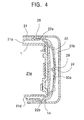
- Figure 4 illustrates a cross sectional view taken along the line B-B in Figure 2;
- Figure 5 is a cross sectional view of the first embodiment when the operation panel is attached with its back side front;
- Figure 6 is a perspective view of a second embodiment;
- Figure 7 illustrates a schematic plan view of the second embodiment when a sleeve engages with a push-out member;
- Figure 8 illustrates a perspective view of part of the second embodiment;
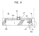
- Figure 9 illustrates a schematic plan view of the first configuration of the second embodiment;
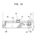
- Figure 10 also illustrates a schematic plan view of the second configuration of the second embodiment; and
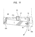
- Figure 11 still illustrates a schematic plan view of the third configuration of the second embodiment.
-
- Embodiments of the present invention will now be described in reference to the accompanying drawings.
- In a vehicle's AV apparatus according to the present invention shown in Figures 1 through 5, an
operation panel 1 has a generally flat and rectangular shape. Like a conventional one, theoperation panel 1 hasvarious operation buttons 2, aninsertion opening 3 for receiving an AV recordation medium such as a cassette tape, adisplay part 4 such as a liquid crystal display, and aselection switch 5 on a front surface thereof. Arelease lever 12 is provided inside theoperation panel 1 near a rightlateral end face 30a of the operation panel. Therelease lever 12 is part of a mechanism for detaching the operation panel from a main body (or unit) 20 of the apparatus. Elongatedgrooves 14 are formed in four corner portions of theoperation panel 1 at upper and lower ends of the lateral end faces 30a and 30b of theoperation panel 1. Among thesegrooves 14 at the four corners, those formed at the upper and lower ends of the rightlateral end face 30a have holes that allow anupper end 19a of a projection member 19 (will be described) and an acutefree end 16 of the release lever 12 (will be described) to penetrate outwards. - A generally
rectangular frame 21 that has a recess to receive theoperation panel 1 is installed in a front portion of the apparatusmain body 20. Onlateral walls frame 21, provided are generally semicircular bar (rod)springs 22. Each of thebar springs 22 has anengagement portion 28 at its approximate center. Thelateral walls projections 24 such that theengagement portions 28 of the bar springs engage with theprojections 24 and are supported by theframe 21. Upper andlower portions bar spring 22 extend inside the frame recess such that they can fit in themating grooves 14 of theoperation panel 1. Upper and lower ends of eachbar spring 22 are, however, buried in upper andlower walls bar spring 22 are buried such that they bias the upper andlower walls engagement portion 28 being a fulcrum. -
Openings 26 are formed in the upper andlower walls bar springs 22 removably fit in theseopenings 26. The ends of thebar springs 22 are forced to come out from the inner walls of the frame recess when theoperation panel 1 is taken out from the frame recess. - A
push rod 27 is provided at an approximate center of aback wall 21e of the framer recess. Thepush rod 27 is supported by acoil spring 29 such that it can move back and forth penetrating the recess backwall 21e. When theoperation panel 1 is fit into the recess of theframe 21, the elastic force of thecoil spring 29 pushes theoperation panel 1 to stably hold theoperation panel 1. When theoperation panel 1 is removed from the frame recess, the elastic force of thecoil spring 29 also pushes theoperation panel 1 to facilitate removal of the operation panel. - The
back wall 21e of the frame recess has an AV recordation medium reception opening 23 at a position corresponding to theinsertion opening 3 of theoperation panel 1. Conductive contacts (not shown) for transmitting electric signals generated upon pushing thebuttons 2 orselection switch 5 on theoperation panel 1 to a reproduction device (replay device) located in the apparatus main body and adapted to reproduce information recorded on an AV recordation medium are provided on the back face of theoperation panel 1 and theback wall 21e of the frame recess. The conductive contacts are arranged to abut each other when theoperation panel 1 is fit in the apparatus main body. - As best seen in Figure 3, when the
operation panel 1 is inserted in the recess of theframe 21 with the front face of the operation panel being directed forwards, therelease lever 12 having an approximately "S" shaped cross section extends through the front and back surfaces of theoperation panel 1. Oneend 12a of the release lever 12 projects from ahole 1a formed in the front face of theoperation panel 1 and theother end 12b projects from anotherhole 1b formed in the back face of theoperation panel 1. Therelease lever 12 is pivotable about asupport shaft 18 and biased in the J direction, i.e., clockwise, by a coil spring (not shown) provided near theshaft 18. Theslots operation panel 1 are configured such that therelease lever 12 can pivot within a predetermined range of angle. - A
projection member 19 having a generally rectangular cross section is installed in theoperation panel 1 such that it moves up and down upon the pivoting movement of therelease lever 12. Theprojection member 19 includes anupper portion 19a, alower portion 19b and acenter portion 19c. Theupper portion 19a is thinner than thecenter portion 19c, and the free end of thelower portion 19b is hemispherical. The free end of thelower portion 19b contacts an upper surface of theright arm 12b of therelease lever 12 at a position offset towards the free end of theright arm 12b from theshaft 18. - When an operator presses the
left end 12a of therelease lever 12 in the K direction in Figure 3 against the biasing force of the coil spring, therelease lever 12 is caused to pivot in the P direction in Figure 3, and theright end 12b is also forced to rotate counterclockwise against the biasing force of the coil spring thereby pushing thelower end 19b upwards. As a result, theprojection member 19 is moved upwards. - When the
projection member 19 is lifted upwards upon the counterclockwise rotation of therelease lever 12 in the drawing, theupper portion 19a of theprojection member 19 protrudes from the opening formed in thegroove 14 at the upper corner of the rightlateral face 30a of theoperation panel 1. This causes theupper portion 22a of thebar spring 22 engaged in thegroove 14 to disengage and expand outside the groove 14 (see Figure 4). - The
left arm 12a of therelease lever 12 has anacute protrusion 16 on a lower surface thereof. Theacute protrusion 16 protrudes from an opening formed in thegroove 14 at the lower corner of the rightlateral face 30a of theoperation panel 1 as the release lever 12 pivots in the K direction in Figure 3. This causes thelower portion 22b of thebar spring 22 engaged in thisgroove 14 to expand outside the groove. - When the AV apparatus equipped with the
operation panel 1 having the above described structure is used, theoperation panel 1 is placed in the recess of theframe 21 of the apparatusmain unit 20 with the front face of theoperation panel 1 being directed forwards. In order to put theoperation panel 1 in place, the operator first inserts the leftlateral end face 30b of theoperation panel 1 into the frame recess so as to engage thegrooves 14 formed at the upper and lower ends of theleft end face 30b with the upper andlower portions left bar spring 22 thereby applying forces on thebar spring 22 in directions to expand the upper andlower portions bar spring 22. While applying such forces, the operator then inserts the rightlateral end face 30a of theoperation panel 1 into the frame recess to engage thegrooves 14 at the upper and lower ends of theright end face 30a with the upper andlower portions right bar spring 22. Accordingly, the fourgrooves 14 formed at the upper and lower corners of the opposite lateral faces 30a and 30b of theoperation panel 1 engage with the upper andlower portions lower portions operation panel 1 in the recess of theframe 21. When inserting theright end 30a of theoperation panel 1 into the frame recess, the operator engages theright grooves 14 with theright bar spring 22 while the back side of theoperation panel 1 is pushing thepush rod 27. In other words, theoperation panel 1 is held in the frame recess by the elastic forces of the bar springs 22 and the elastic force of thecoil spring 29 of thepush rod 27 that urges theoperation panel 1 forwards from the back side thereof so that there is a good balance between the two different elastic forces. This contributes to enhanced retention of theoperation panel 1 in the frame recess. - In order to remove the
operation panel 1 from the frame recess with its front side being directed forwards, the operator pushes down theend 12a of therelease lever 12 in the K direction in Figure 3. Therelease lever 12 then pivots about thesupport shaft 18 in the K direction, i.e., counterclockwise direction in Figure 3, against the biasing force of the coil spring acting in the J direction. At the same time, theother end 12b of therelease lever 12 pivots in the P direction against the biasing force directed in the O direction, whereby theprojection member 19 is lifted upwards. Upon this ascending movement, theupper end 19a of theprojection member 19 protrudes from the opening formed in the upper end of the rightlateral end face 30a of the operation panel 1 (this opening is formed in thegroove 14 at the upper right corner of the operation panel 1), and moves to expand theupper portion 22a of thebar spring 22 against the elastic force of thebar spring 22 fit in thegroove 14. As a result, thegroove 14 and thebar spring 22 are disengaged from each other. When theupper portion 22a of thebar spring 22 is caused to expand, the upper end of thebar spring 22 protrudes from theopening 26 formed in theupper wall 21a of theframe 21 in the vicinity of the right end of theupper wall 21a. Since provision of theopening 26 allows theprojection member 19 to expand thebar spring 22 to a larger extent, the disengagement between thegroove 14 and thebar spring 22 is ensured. - As the operator causes the
release lever 12 to pivot, theacute projection 16 at the lower portion of therelease lever 12 pivots in the K direction together with the pushed downend 12a of therelease lever 12 while the above described movement is occurring. Theacute projection 16 then protrudes from the opening formed at the lower end of the rightlateral face 30a of the operation panel 1 (this opening is formed in thegroove 14 at the lower right corner of the operation panel) and pivots to expand thelower portion 22b of thebar spring 22 against the elastically resisting force of thelower portion 22b of thebar spring 22 fit in thegroove 14. In this manner, theacute extension 16 terminates the engagement between thelower portion 22b of thebar spring 22 and thegroove 14, and this releases the retention imposed by thebar spring 22 on the rightlateral face 30a of theoperation panel 1. When thelower portion 22b of thebar spring 22 is expanded, the lower free end of thebar spring 22 protrudes from theopening 2 formed in thelower wall 21d of theframe 21 near the right end of thelower wall 21d. As the retention condition made by theright bar spring 22 is terminated, the balance between the retention resulting from the expanding force of thebar spring 22 and the pushing force of thepush rod 29 is lost so that thepush rod 27 urges theoperation panel 1 forwards from the back side of theoperation panel 1. When the operator pulls out the pushed-out rightlateral face 30a of theoperation panel 1 from the recess of theframe 21, the retention imposed by theleft bar spring 22 on the leftlateral face 30b of the operation panel is terminated so that theoperation panel 1 is completely separated from the frame recess. - When the operator releases the pivoting
release lever 12, i.e., the operator stops pushing down theend 12a of therelease lever 12 in the K direction and frees therelease lever 12, then therelease lever 12 is caused to pivot in the J direction or clockwise by the biasing force of the coil spring, and theends acute projection 16 and theprojection member 19 return to the original positions. - When the AV apparatus equipped with the above described
operation panel 1 is not utilized, that is, when the operator(s) (i.e., car driver and passenger(s)) leaves the car, the operator wants to prevent the AV apparatus from being stolen. In such a case, the operator turns theoperation panel 1 to use its back side a fake front face, and places theoperation panel 1 into the frame recess of the apparatusmain unit 20. The operation panel is designed to fit in the frame recess in a similar manner as when the operation panel fits in the frame recess with its front side being directed forwards. - Next, removal of the
operation panel 1 from the frame recess with its back side being directed forwards will be described. - As best understood from Figure 5, the
operation panel 1 is placed in the frame recess with its front side being subjected to theback wall 21e of the frame recess. Thus, theend 12b of therelease lever 12 now protrudes forwards (to the left in the drawing) from anopening 1b in the back wall of theoperation panel 1. In this condition, therelease lever 12 is biased to pivot in the M direction or counterclockwise in the drawing by a coil spring (not shown) installed near thesupport shaft 18. In order to remove theoperation panel 1 from the illustrated condition, the operator pushes up the exposedend 12b of therelease lever 12 in the L direction against the biasing force in the M direction. Upon this push up movement, therelease lever 12 pivots in the L direction or clockwise about thesupport shaft 18, and theend 12b of therelease lever 12 moves theprojection member 19 upwards. This ascending movement causes theupper end 19a of theelongated member 19 to protrude from the opening formed at the upper end of thelateral end face 30a of the operation panel 1 (this opening is formed in the groove 14), and move expanding theupper portion 22a of thebar spring 22 against the resilient force of theupper portion 22a of the bar spring fit in thegroove 14. As a result, the engagement between thegroove 14 and thebar spring 22 is released. When theupper portion 22a of the bar spring is expanded, the upper free end of thebar spring 22 protrudes from theopening 26 formed in theupper wall 21a of the frame recess near the left end of theupper wall 21a. - As the operator causes the
release lever 12 to pivot, theacute projection 16 on the lower portion of therelease lever 12 also pivots in the Q direction against the biasing force in the N direction in the drawing together with theend 12a of therelease lever 12 while the above described movement is proceeding. Theacute projection 16 then protrudes from the opening formed at the lower end of the rightlateral face 30a of the operation panel 1 (or the opening formed in the groove 14) and pivots to expand thelower portion 22b of thebar spring 22 against the elastic force of thelower portion 22b of thebar spring 22 fit in thegroove 14. In this manner, theacute projection 16 disengages the lower portion of thebar spring 22 from thegroove 14, and therefore the retention imposed by thebar spring 22 on the rightlateral face 30a of theoperation panel 1 is released. When thelower portion 22b of the bar spring is expanded, the lower free end of the bar spring protrudes from theopening 26 formed in thelower wall 21d of the frame recess near the left end of thelower wall 21d. Since there is no retention by thebar spring 22, the balance between the retention with the elastic force of thebar spring 22 and the pushing force of thepush rod 27 is lost and thepush rod 27 pushes theoperation panel 1 forwards. As the operator pulls the pushed-out rightlateral face 30a of theoperation panel 1 out of the recess of theframe 21, the retention imposed by thebar spring 22 on the leftlateral face 30b is released so that theoperation panel 1 is completely taken out from the frame recess. - When the operator releases the pivoting
release lever 12, i.e., the operator stops pushing up theend 12b of therelease lever 12 in the L direction and frees therelease lever 12, then therelease lever 12 is caused to pivot in the M direction or clockwise by the biasing force of the coil spring, and both theends release lever 12 are returned to the respective original positions. At the same time, theacute projection 16 and theprojection member 19 return to the original positions. - Referring to Figures 6 through 11, illustrated is a second embodiment of the present invention. As best shown in Figure 6, the lateral faces 30a and 30b of the
operation panel 1 haveconcave portions 60 that extend in parallel to the front surface of theoperation panel 1. - Bar springs 70 are arranged on the
back wall 21e of the frame recess near longitudinal ends of theback wall 21e such that they protrude to engage with theconcave portions 60 formed in the lateral end faces of theoperation panel 1. The vertical portion of each of the bar springs 70 has a generallycylindrical sleeve 72, and thesleeve 72 fits in therecess 60 when theoperation panel 1 fits in the recess of theframe 21. The bar springs 70 normally bias the associatedsleeves 72 in directions to enhance the engagement between thesleeves 72 and therecesses 60. - The
groove 60 formed in the rightlateral face 30a of theoperation panel 1 has an opening that allows a free end of a push-out member 62 (will be described) to protrude from and retract in this opening. - Referring particularly to Figure 8, the push-
out member 62 has a generally "L" shape, and its shorter segment that extends perpendicularly to a lock member 64 (will be described) and extends/retracts in theopening 62 formed in therecess 60 has adepression 62a adapted to engage with thesleeve 72. This shorter segment is referred to as a front portion of the push-out member 62. The cross sectional shape of thedepression 62a is a trough defined by two inclined surfaces to insure the engagement with thesleeve 72. Two generally pole-shapedsupport members 65 are buried in the longer segment of the "L"-shaped push-out member 62 at their one ends. The other ends of thesupport members 65 are slidably received in aguide groove 80 extending in parallel to the longer segment of the push-out member 62. Theguide groove 80 is formed in theoperation panel 1. - The
lock member 64 having a generally rectangular shape extends in theoperation panel 1 near the rightlateral end 30a of theoperation panel 1. Thelock member 64 also penetrates the front and back faces of theoperation panel 1 through openings formed in the front and back faces of the operation panel so that both ends of thelock member 64 are exposed. Thelock member 64 is supported by theoperation panel 1 such that it can move in a direction perpendicular to the front face of theoperation panel 1. By pushing one of the exposed ends of thelock member 64, the operator can move thelock member 64. - A through
hole 66 having a generally "V" shape is formed in an approximate middle of thelock member 64, and one of the cylindrical support members 65 (one positioned closer to the shorter segment of the L-shaped push-out member 62 in Figures 7 and 8) penetrates the throughhole 66. Thelock member 64 is biased by fourcoil springs 68 located in theoperation panel 1 such that its ends are pulled in opposite directions. When the operator does not push the exposed ends of thelock member 64, therefore, thecylindrical support member 65 is always kept at the center of the throughhole 66 by the biasing, forces of the coil springs 65. When thesupport member 65 is situated at the center of the throughhole 66, the front portion of the push-out member 62 is in a retracted position. - As particularly obvious from Figure 8, if the operator presses one of the exposed ends of the
lock member 64, thelock member 64 moves in a direction perpendicular to theoperation panel 1. Upon this movement of thelock member 64, thesupport member 65 slides in the V-shaped throughhole 66, and the lower end of thesupport member 65 slides in theguide groove 80. Consequently, the end face having thedepression 62a of the front portion of the push-out member 62 protrudes from the opening formed in thegroove 60 of the right end face of the operation panel. When the operator releases thelock member 64, on the other hand, the biasing forces of the coil springs 68 cause thelock member 64 to return to the original position. Specifically, thesupport member 65 returns to the center of the throughhole 66 and the front portion of the push-out member 62 retracts in theoperation panel 1. - A
push rod 27 is provided at an approximate center of theback wall 21e of the framer recess. Thepush rod 27 is supported by acoil spring 29 such that it can move back and forth penetrating theback wall 21e of the frame recess. When theoperation panel 1 is fit into the recess of theframe 21, the elastic force of thecoil spring 29 pushes theoperation panel 1 to stably hold theoperation panel 1. When theoperation panel 1 is removed from the frame recess, the elastic force of thecoil spring 29 also pushes theoperation panel 1 to facilitate removal of the operation panel. - In order to place the
operation panel 1 in the recess of theframe 21 formed in the front area of the apparatusmain unit 20 with the front face of theoperation panel 1 being directed forwards, the operator first inserts the leftlateral end face 30b of theoperation panel 1 into the frame recess so as to engage theleft sleeve 72 with theleft recess 60. While maintaining the engaged condition, the operator then expands theleft bar spring 70 that carries theleft sleeve 72. Subsequently, the operator inserts the rightlateral end face 30a of theoperation panel 1 into the frame recess to engage theright sleeve 72 with theright recess 60. At this point, thesleeves 72 engaged with the lateral faces 30a and 30b of theoperation panel 1 clamp and bias theoperation panel 1 with the elastic forces of the bar springs 70. In this manner, theoperation panel 1 is kept in the frame recess. In addition, thepush rod 27 is provided at the approximate center of theback wall 21e of the frame recess such that it can move back and forth with thecoil spring 27. When inserting theright end 30a of theoperation panel 1 into the frame recess, therefore, the operator engages theright sleeve 72 with themating recess 60 while the back side of theoperation panel 1 is pushing thepush rod 27. Thepush rod 27 that pushes theoperation panel 1 forwards with the elastic force of thecoil spring 29 further ensures the reliable retention of theoperation panel 1 in the frame recess. - It should be noted that the above described manner of inserting and retaining the
operation panel 1 in the frame recess is applicable when theoperation panel 1 is inserted with its front side being directed to theback wall 21e of the frame recess. - Removal of the
operation panel 1 from the frame recess with its front side being directed forwards will be described below. As particularly illustrated in Figure 7, thesleeves 72 engage with thegrooves 60 formed in the end faces 30a and 30b of theoperation panel 1 and thesupport member 65 is positioned at the center of the throughhole 66 when theoperation panel 1 is in the retained condition. As the operator pushes the front exposed end of thelock member 64 in the R direction in Figure 8, thelock member 64 moves backwards. Upon this movement, thesupport member 65 moves along the throughhole 66, and the lower end of thesupport member 65 moves along theguide groove 80. Consequently, the push-out member 62 moves in the S direction in Figure 8, and the front portion or thedepression 62a of the push-out member 62 protrudes from the opening formed in theright recess 60 and engages with thesleeve 72. As the operator further pushes thelock member 64, thedepression 62a pushes thesleeve 72 thereby expanding thebar spring 70 and disengaging the sleeve 74 from therecess 60. - As the
right sleeve 72 is disengaged from theright recess 60 formed in the rightlateral face 30a of the operation panel as shown in Figure 10 from the condition shown in Figure 9 in which theoperation panel 1 is fit in the frame recess, the elastic force of thecoil spring 29 causes thepush rod 27 to push theoperation panel 1 forwards from the back side of the operation panel so that theright face 30a of theoperation panel 1 is pushed out (Figure 11). As the operator pulls out the ejectedright end 30a of theoperation panel 1 from the frame recess, the engagement between theleft recess 60 formed in theleft end 30b of theoperation panel 1 and themating sleeve 72 is terminated so that theoperation panel 1 is completely separated from the frame recess. If the operator stops pushing the front end of thelock member 64, thelock member 64 is caused to move in a direction opposite the R direction by the biasing forces of the coil springs 68 in Figure 8. Accordingly, thesupport member 65 returns to the center of the throughhole 66. It should be noted that the above described manner of removing theoperation panel 1 from the recess of theframe 21 can be applied when theoperation panel 1 is fit in the frame recess with its front side being exposed to the rear wall of the frame recess. In this case, the operator pushes the other end of thelock member 64 to eject theoperation panel 1. - In the first and second embodiments described above, the surfaces or other portions of the bar springs 22, 70, the
operation panel 1, thegrooves 14, thedepressions 60, theframe 21 and the apparatusmain unit 20 may be appropriately bent, surface-treated and/or shape-treated to insure proper push-in retention of theoperation panel 1 in the apparatusmain unit 20. - As the theftproof structure, provided is the operation panel attaching/detaching mechanism of simple construction that allows the operation panel to be attached to the apparatus main unit with either the front or back side of the operation panel being directed forwards (or exposed), and to be detached from the apparatus main unit.
Claims (6)
- An audio and/or video apparatus installed in a vehicle comprising:a main unit installed in a vehicle and adapted to reproduce an audio and/or video signal;an operation panel independent of the main unit and adapted to operate the main unit; anda retention mechanism for releasably retaining the operation panel relative to the main unit with either a front or back side of the operation panel being directed forwards.
- The audio and/or video apparatus installed in a vehicle according to claim 1, wherein the retention mechanism includes a first mechanism for retaining the operation panel in the main unit with the front side of the operation panel being directed forwards and a second mechanism for retaining the operation panel in the main unit with the back side of the operation panel being directed forwards, and the first and second mechanisms are the same mechanism.
- The audio and/or video apparatus installed in a vehicle according to claim 1 or 2, wherein the retention mechanism includes retaining device for retaining lateral faces of the operation panel in the main unit and release device provided in the operation panel for releasing retention of the retaining device.
- The audio and/or video apparatus installed in a vehicle according to claim 3, wherein the operation panel has an elongated shape, and the retaining device retains longitudinal end faces of the operation panel in the main unit.
- The audio and/or video apparatus installed in a vehicle according to claim 3, wherein the retention mechanism further includes a frame portion having a recess that can receive the operation panel in a fixed relation relative to the main unit, and the retaining device is an engagement mechanism that engages with lateral or outer faces of the operation panel when the operation panel is received in the recess of the frame portion.
- The audio and/or video apparatus installed in a vehicle according to claim 5, wherein the retention mechanism includes a resilient member provided in the recess of the frame portion and an engagement portion provided on the lateral or outer faces of the operation panel for engaging with the resilient member when the operation panel is received in the recess of the frame portion, and the release device includes a push-out mechanism located in the operation panel for pushing out the resilient member, which engages with the engagement portion, from the engagement portion.
Applications Claiming Priority (2)
| Application Number | Priority Date | Filing Date | Title |
|---|---|---|---|
| JP2000257721 | 2000-08-28 | ||
| JP2000257721A JP2002074922A (en) | 2000-08-28 | 2000-08-28 | On-vehicle audio and/or video apparatus |
Publications (3)
| Publication Number | Publication Date |
|---|---|
| EP1184227A2 true EP1184227A2 (en) | 2002-03-06 |
| EP1184227A3 EP1184227A3 (en) | 2004-06-09 |
| EP1184227B1 EP1184227B1 (en) | 2005-11-02 |
Family
ID=18746143
Family Applications (1)
| Application Number | Title | Priority Date | Filing Date |
|---|---|---|---|
| EP01119721A Expired - Lifetime EP1184227B1 (en) | 2000-08-28 | 2001-08-24 | Audio and/or video apparatus for vehicle, releasably retaining the operation panel |
Country Status (4)
| Country | Link |
|---|---|
| US (1) | US6650026B2 (en) |
| EP (1) | EP1184227B1 (en) |
| JP (1) | JP2002074922A (en) |
| DE (1) | DE60114529T2 (en) |
Families Citing this family (25)
| Publication number | Priority date | Publication date | Assignee | Title |
|---|---|---|---|---|
| US6642629B2 (en) * | 2000-12-28 | 2003-11-04 | Intel Corporation | Audio system with removable, active faceplate |
| DE10323467A1 (en) * | 2003-05-23 | 2004-12-30 | Robert Bosch Gmbh | multimedia terminal |
| DE102004026456A1 (en) * | 2004-05-29 | 2005-12-29 | Sauer-Danfoss Aps | Joystick assembly |
| US8400572B2 (en) * | 2005-09-16 | 2013-03-19 | Voxx International Corporation | Interchangeable switch assembly for media device |
| JP4709222B2 (en) * | 2005-09-28 | 2011-06-22 | クラリオン株式会社 | In-vehicle audio equipment |
| JP2007091033A (en) | 2005-09-28 | 2007-04-12 | Fujitsu Ten Ltd | Electronic device |
| JP4366352B2 (en) * | 2005-10-19 | 2009-11-18 | 富士通テン株式会社 | Electronic equipment |
| JP2008141076A (en) * | 2006-12-04 | 2008-06-19 | Fujitsu Ten Ltd | Attaching/detaching device of mobile electronic equipment |
| US20080161950A1 (en) * | 2006-12-28 | 2008-07-03 | Fujitsu Ten Limited | Electronic system, electronic apparatus and method of operating audio unit |
| US7684200B2 (en) | 2006-12-28 | 2010-03-23 | Fujitsu Ten Limited | Electronic apparatus and electronic system |
| JP2008137559A (en) | 2006-12-04 | 2008-06-19 | Fujitsu Ten Ltd | On-vehicle electronic system, on-vehicle electronic device, and power control method for portable electronic device |
| US20080162044A1 (en) * | 2006-12-28 | 2008-07-03 | Fujitsu Ten Limited | In-vehicle electronic apparatus and in-vehicle electronic system |
| US7904236B2 (en) | 2006-12-28 | 2011-03-08 | Fujitsu Ten Limited | Electronic apparatus and electronic system |
| US20080157999A1 (en) * | 2006-12-28 | 2008-07-03 | Fujitsu Ten Limited | Electronic apparatus, electronic system and method of controlling audio output |
| US7860643B2 (en) | 2006-12-28 | 2010-12-28 | Fujitsu Ten Limited | In-vehicle detachably electronic apparatus and in-vehicle electronic system |
| US8706396B2 (en) * | 2006-12-28 | 2014-04-22 | Fujitsu Ten Limited | Electronic apparatus and electronic system |
| US7765046B2 (en) | 2006-12-28 | 2010-07-27 | Fujitsu Ten Limited | In-vehicle electronic apparatus and in-vehicle electronic system |
| US20080159557A1 (en) * | 2006-12-27 | 2008-07-03 | Fujitsu Ten Limited | Electronic apparatus, electronic system and method of controlling sound output |
| JP4842785B2 (en) | 2006-12-04 | 2011-12-21 | 富士通テン株式会社 | In-vehicle electronic system and in-vehicle electronic device |
| US7774104B2 (en) | 2006-12-27 | 2010-08-10 | Fujitsu Ten Limited | Electronic apparatus and electronic system |
| US7610448B2 (en) * | 2006-12-27 | 2009-10-27 | Intel Corporation | Obscuring memory access patterns |
| US7869196B2 (en) | 2006-12-28 | 2011-01-11 | Fujitsu Ten Limited | Electronic apparatus |
| US20100103598A1 (en) * | 2008-10-24 | 2010-04-29 | Fujitsu Ten Limited | Electronic apparatus and method for the same |
| US8481832B2 (en) * | 2011-01-28 | 2013-07-09 | Bruce Lloyd | Docking station system |
| US9768572B1 (en) | 2016-04-29 | 2017-09-19 | Banner Engineering Corp. | Quick-connector conversion system for safety controller |
Citations (1)
| Publication number | Priority date | Publication date | Assignee | Title |
|---|---|---|---|---|
| JPH09237978A (en) | 1995-12-29 | 1997-09-09 | Sony Corp | Electronic device and recording and / or reproducing apparatus for recording medium |
Family Cites Families (6)
| Publication number | Priority date | Publication date | Assignee | Title |
|---|---|---|---|---|
| US5554966A (en) * | 1992-01-20 | 1996-09-10 | Pioneer Electronic Corporation | Car-stereo with removable control panel, alarm, and power conservation |
| US5575544A (en) * | 1992-08-26 | 1996-11-19 | Clarion Co., Ltd. | Vehicle-mounted equipment anti-theft mechanism |
| EP0960781A3 (en) * | 1993-04-30 | 2000-05-24 | Shintom Co., Ltd | Car-mounted sound device |
| JP3322781B2 (en) * | 1995-10-30 | 2002-09-09 | 株式会社ケンウッド | Automotive electronics |
| JP3274964B2 (en) * | 1996-03-29 | 2002-04-15 | 株式会社ケンウッド | Automotive electronics |
| JPH11213646A (en) * | 1998-01-20 | 1999-08-06 | Kenwood Corp | On-vehicle electronic apparatus |
-
2000
- 2000-08-28 JP JP2000257721A patent/JP2002074922A/en not_active Abandoned
-
2001
- 2001-08-24 EP EP01119721A patent/EP1184227B1/en not_active Expired - Lifetime
- 2001-08-24 DE DE2001614529 patent/DE60114529T2/en not_active Expired - Fee Related
- 2001-08-24 US US09/935,640 patent/US6650026B2/en not_active Expired - Fee Related
Patent Citations (1)
| Publication number | Priority date | Publication date | Assignee | Title |
|---|---|---|---|---|
| JPH09237978A (en) | 1995-12-29 | 1997-09-09 | Sony Corp | Electronic device and recording and / or reproducing apparatus for recording medium |
Also Published As
| Publication number | Publication date |
|---|---|
| DE60114529T2 (en) | 2006-08-10 |
| US20020024597A1 (en) | 2002-02-28 |
| EP1184227A3 (en) | 2004-06-09 |
| JP2002074922A (en) | 2002-03-15 |
| DE60114529D1 (en) | 2005-12-08 |
| US6650026B2 (en) | 2003-11-18 |
| EP1184227B1 (en) | 2005-11-02 |
Similar Documents
| Publication | Publication Date | Title |
|---|---|---|
| EP1184227B1 (en) | Audio and/or video apparatus for vehicle, releasably retaining the operation panel | |
| EP1352786B1 (en) | Electronic instrument | |
| US4784361A (en) | Automotive electronic device mounting assembly | |
| US4109286A (en) | Cassette tape recorder with cassette eject mechanism | |
| JPH064950A (en) | Cassette housing mechanism in acoustic equipment | |
| JP3930242B2 (en) | Electronics | |
| US6396658B1 (en) | Media cartridge magazine including structure for latching cartridges inserted into the magazine | |
| JP3469823B2 (en) | Cartridge containing disk and signal recording / reproducing apparatus for disk | |
| JP2899780B2 (en) | Cassette holder device | |
| KR100695202B1 (en) | Anti-theft device for information storage media | |
| US5598925A (en) | Holder for a sound recording medium housing having rattling noise prevention means | |
| GB2239732A (en) | Cassette loading apparatus | |
| KR100549791B1 (en) | Anti-theft device for information storage media | |
| KR100246042B1 (en) | Car Audio System | |
| JPS6141170Y2 (en) | ||
| JP2533889Y2 (en) | Operating device for in-vehicle equipment | |
| JPH1051154A (en) | Push button mechanism and unlock push button mechanism | |
| JPH04132686U (en) | In-vehicle device operating device | |
| JP3386920B2 (en) | Mounting device | |
| JPH09251766A (en) | On-vehicle electronic equipment | |
| JP2616501B2 (en) | Cassette loading device | |
| JPH07282173A (en) | Card reader unit | |
| JP2591088Y2 (en) | Device operation unit attachment / detachment device | |
| JPH08156471A (en) | IC card removal prevention device | |
| JPS6297192A (en) | Loading and unloading device for video deck |
Legal Events
| Date | Code | Title | Description |
|---|---|---|---|
| PUAI | Public reference made under article 153(3) epc to a published international application that has entered the european phase |
Free format text: ORIGINAL CODE: 0009012 |
|
| AK | Designated contracting states |
Kind code of ref document: A2 Designated state(s): AT BE CH CY DE DK ES FI FR GB GR IE IT LI LU MC NL PT SE TR |
|
| AX | Request for extension of the european patent |
Free format text: AL;LT;LV;MK;RO;SI |
|
| PUAL | Search report despatched |
Free format text: ORIGINAL CODE: 0009013 |
|
| AK | Designated contracting states |
Kind code of ref document: A3 Designated state(s): AT BE CH CY DE DK ES FI FR GB GR IE IT LI LU MC NL PT SE TR |
|
| AX | Request for extension of the european patent |
Extension state: AL LT LV MK RO SI |
|
| 17P | Request for examination filed |
Effective date: 20040608 |
|
| 17Q | First examination report despatched |
Effective date: 20040820 |
|
| AKX | Designation fees paid |
Designated state(s): DE FR GB |
|
| GRAP | Despatch of communication of intention to grant a patent |
Free format text: ORIGINAL CODE: EPIDOSNIGR1 |
|
| GRAS | Grant fee paid |
Free format text: ORIGINAL CODE: EPIDOSNIGR3 |
|
| GRAA | (expected) grant |
Free format text: ORIGINAL CODE: 0009210 |
|
| AK | Designated contracting states |
Kind code of ref document: B1 Designated state(s): DE FR GB |
|
| REG | Reference to a national code |
Ref country code: GB Ref legal event code: FG4D |
|
| REF | Corresponds to: |
Ref document number: 60114529 Country of ref document: DE Date of ref document: 20051208 Kind code of ref document: P |
|
| ET | Fr: translation filed | ||
| REG | Reference to a national code |
Ref country code: GB Ref legal event code: 746 Effective date: 20060627 |
|
| PGFP | Annual fee paid to national office [announced via postgrant information from national office to epo] |
Ref country code: FR Payment date: 20060905 Year of fee payment: 6 |
|
| PLBE | No opposition filed within time limit |
Free format text: ORIGINAL CODE: 0009261 |
|
| STAA | Information on the status of an ep patent application or granted ep patent |
Free format text: STATUS: NO OPPOSITION FILED WITHIN TIME LIMIT |
|
| PGFP | Annual fee paid to national office [announced via postgrant information from national office to epo] |
Ref country code: GB Payment date: 20060912 Year of fee payment: 6 |
|
| 26N | No opposition filed |
Effective date: 20060803 |
|
| PGFP | Annual fee paid to national office [announced via postgrant information from national office to epo] |
Ref country code: DE Payment date: 20061031 Year of fee payment: 6 |
|
| REG | Reference to a national code |
Ref country code: FR Ref legal event code: ST Effective date: 20070430 |
|
| REG | Reference to a national code |
Ref country code: FR Ref legal event code: D3 |
|
| GBPC | Gb: european patent ceased through non-payment of renewal fee |
Effective date: 20070824 |
|
| PG25 | Lapsed in a contracting state [announced via postgrant information from national office to epo] |
Ref country code: FR Free format text: LAPSE BECAUSE OF NON-PAYMENT OF DUE FEES Effective date: 20060831 |
|
| REG | Reference to a national code |
Ref country code: FR Ref legal event code: ST Effective date: 20080430 |
|
| PG25 | Lapsed in a contracting state [announced via postgrant information from national office to epo] |
Ref country code: DE Free format text: LAPSE BECAUSE OF NON-PAYMENT OF DUE FEES Effective date: 20080301 |
|
| PG25 | Lapsed in a contracting state [announced via postgrant information from national office to epo] |
Ref country code: GB Free format text: LAPSE BECAUSE OF NON-PAYMENT OF DUE FEES Effective date: 20070824 |