EP1184211A2 - Shock absorbing hitch - Google Patents
Shock absorbing hitch Download PDFInfo
- Publication number
- EP1184211A2 EP1184211A2 EP01119639A EP01119639A EP1184211A2 EP 1184211 A2 EP1184211 A2 EP 1184211A2 EP 01119639 A EP01119639 A EP 01119639A EP 01119639 A EP01119639 A EP 01119639A EP 1184211 A2 EP1184211 A2 EP 1184211A2
- Authority
- EP
- European Patent Office
- Prior art keywords
- connecting means
- rigid container
- container
- hitch
- rigid
- Prior art date
- Legal status (The legal status is an assumption and is not a legal conclusion. Google has not performed a legal analysis and makes no representation as to the accuracy of the status listed.)
- Withdrawn
Links
- 230000035939 shock Effects 0.000 title description 2
- 239000012530 fluid Substances 0.000 claims description 20
- 229920001971 elastomer Polymers 0.000 claims description 18
- 239000000463 material Substances 0.000 claims description 10
- 239000013536 elastomeric material Substances 0.000 claims description 9
- 238000013016 damping Methods 0.000 abstract description 22
- 239000000806 elastomer Substances 0.000 description 16
- 230000006835 compression Effects 0.000 description 3
- 238000007906 compression Methods 0.000 description 3
- 239000002689 soil Substances 0.000 description 3
- 238000010276 construction Methods 0.000 description 2
- 238000003971 tillage Methods 0.000 description 2
- 235000008694 Humulus lupulus Nutrition 0.000 description 1
- 239000006096 absorbing agent Substances 0.000 description 1
- 230000000694 effects Effects 0.000 description 1
- 230000003993 interaction Effects 0.000 description 1
- 230000002452 interceptive effect Effects 0.000 description 1
Images

Classifications
-
- F—MECHANICAL ENGINEERING; LIGHTING; HEATING; WEAPONS; BLASTING
- F16—ENGINEERING ELEMENTS AND UNITS; GENERAL MEASURES FOR PRODUCING AND MAINTAINING EFFECTIVE FUNCTIONING OF MACHINES OR INSTALLATIONS; THERMAL INSULATION IN GENERAL
- F16F—SPRINGS; SHOCK-ABSORBERS; MEANS FOR DAMPING VIBRATION
- F16F3/00—Spring units consisting of several springs, e.g. for obtaining a desired spring characteristic
- F16F3/08—Spring units consisting of several springs, e.g. for obtaining a desired spring characteristic with springs made of a material having high internal friction, e.g. rubber
- F16F3/10—Spring units consisting of several springs, e.g. for obtaining a desired spring characteristic with springs made of a material having high internal friction, e.g. rubber combined with springs made of steel or other material having low internal friction
-
- B—PERFORMING OPERATIONS; TRANSPORTING
- B60—VEHICLES IN GENERAL
- B60D—VEHICLE CONNECTIONS
- B60D1/00—Traction couplings; Hitches; Draw-gear; Towing devices
- B60D1/14—Draw-gear or towing devices characterised by their type
- B60D1/145—Draw-gear or towing devices characterised by their type consisting of an elongated single bar or tube
-
- B—PERFORMING OPERATIONS; TRANSPORTING
- B60—VEHICLES IN GENERAL
- B60D—VEHICLE CONNECTIONS
- B60D1/00—Traction couplings; Hitches; Draw-gear; Towing devices
- B60D1/48—Traction couplings; Hitches; Draw-gear; Towing devices characterised by the mounting
- B60D1/50—Traction couplings; Hitches; Draw-gear; Towing devices characterised by the mounting resiliently mounted
-
- F—MECHANICAL ENGINEERING; LIGHTING; HEATING; WEAPONS; BLASTING
- F16—ENGINEERING ELEMENTS AND UNITS; GENERAL MEASURES FOR PRODUCING AND MAINTAINING EFFECTIVE FUNCTIONING OF MACHINES OR INSTALLATIONS; THERMAL INSULATION IN GENERAL
- F16F—SPRINGS; SHOCK-ABSORBERS; MEANS FOR DAMPING VIBRATION
- F16F3/00—Spring units consisting of several springs, e.g. for obtaining a desired spring characteristic
- F16F3/08—Spring units consisting of several springs, e.g. for obtaining a desired spring characteristic with springs made of a material having high internal friction, e.g. rubber
- F16F3/087—Units comprising several springs made of plastics or the like material
Definitions
- the invention relates to a hitch for connecting a drive vehicle to an object which is to be moved.
- the hitch has means for damping forces between the object and the drive vehicle.
- Power hop is a condition of vehicle in which a vehicle (tractor) bounces, primarily in the vertical mode, and causes ride discomfort for the vehicle operator. Power hop occurs when a vehicle (tractor) is pulling an attachment (implement) which applies a significant resistance force to the vehicle.
- This resistance force of the attachment in the fore-aft (tangential) direction can reach up to 50% to 100% of the vertical load of the vehicle, and is constantly varying.
- This resistance force of the attachment is referred to as the drawbar load.
- the variation of these resistance forces contributes to power hop.
- Power hop can occur on any surface, with any vehicle pulling any sort of object.
- An agricultural tractor pulling an implement disk, chisel plow, field cultivator, subsoiler ripper
- soil tillage conditions is one such example.
- the invention relates to a hitch for connecting a drive vehicle (10) to an object to be moved (12).
- the hitch (14a,40) is characterized by (a) a rigid container made of a rigid material, (b) a first connecting means (16) associated with a first end of the rigid container wherein an exterior portion of the first connecting means has a first end (16a) outside the rigid container and an interior portion (16b) within the rigid container, the first connecting means being movable relative to the rigid container, (c) a second connecting means (18) associated with a second end (21a) of the rigid container wherein an exterior portion of the second connecting means is outside the rigid container and an interior portion (18b) is within the rigid container, and the second connecting means is movable relative to the rigid container, (d) a first resilient means (22, 42) contained within the rigid container between the first and second connecting means, a second resilient means (24, 46) contained within the rigid container between a first end of the rigid container and the first connecting means, and a third resilient means (26,
- At least one of the resilient means is elastomeric material, and is preferably rubber.
- At least one of the resilient means is a spring.
- a hydraulic fluid (74) is contained within the container and restricts the movement of the first or second connecting means (16, 18).
- the hydraulic fluid flows through one or more channels provided in one or both of the interior portions (16b, 18b).
- a hitch (14a) is characterized by (a) a box of rigid material having a cross section having at least two parallel sides (21), (b) a first connecting means (16) is associated with a first end (21b) of the box wherein an exterior portion of the first connecting means is outside the box and an interior portion (16b) is within the box, and the first connecting means is movable relative to the box between the at least two parallel sides, (c) a second connecting means (18) is associated with a second end (21a) of the box wherein an exterior portion of the second connecting means is outside the box and an interior portion (18b) is within the box, and the second connecting means is movable relative to the box between the at least two parallel sides, (d) a first elastomeric material (22) disposed within the box between the first connecting means (16) and the second connecting means (18), (e) a second elastomeric material (24) disposed within the box between the interior portion (16b) of the first connecting means (16) and the box, and (
- a hitch (40) is characterized by (a) a rigid container made of a rigid material, (b) a first connecting means (16) associated with a first end of the rigid container wherein an exterior portion of the first connecting means has a first end (16a) outside the rigid container and an interior portion with a second end (16b) within the rigid container, the first connecting means being movable relative to the rigid container, (c) a second connecting means (18) associated with a second end (21a) of the rigid container wherein an exterior portion of the second connecting means is outside the rigid container and an interior portion (18b) is within the rigid container, and the second connecting means is movable relative to the rigid container, (d) a first spring (42) contained within the rigid container between the first and second connecting means, a second spring (46) contained within the rigid container between a first end of the rigid container and the first connecting means, and a third spring (44) within the rigid container between a second end of the rigid container and the second connecting means.
- the hitch is characterized by (a) a container made of a rigid material, (b) a first connecting means (16) associated with a first end (21b) of the container wherein an exterior portion of the first connecting means is outside the container and an interior portion with a second end (16b) is within the container, and the first connecting means is movable relative to the container, (c) a second connecting means (18) associated with a second end (21a) of the container wherein an exterior portion of the second connecting means is outside the container and an interior portion with a second end (18b) is within the container, and the second connecting means is movable relative to the container, (d) a hydraulic fluid (74) contained within the container where hydraulic fluid (74) restricts the movement of the fluid and second connecting means (18), and (e) a first spring (42) contained within the rigid container between the first and second connecting means, a second spring (46) contained within the rigid container between a first end of the rigid container and said the connecting means (16), and a third spring (44) within the rigid container between
- the container of the hitch may comprise a cylinder made of a rigid material, wherein the first and second connecting means are associated with opposed ends of the cylinder.
- a hydraulic fluid may be contained within the cylinder to restrict the movement of the first and second connecting means.
- the hitch may comprise a rigid container made of a rigid material wherein a first spring is contained within the rigid container between the first and second connecting means, a second spring is contained within the rigid container between a first end of the rigid container and the first connecting means, and a third spring is within the rigid container between a second end of the rigid container and the second connecting means
- the invention is directed primarily toward the use of heavy vehicles that are used for pulling attachments with high resistive forces.
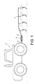
- a driving vehicle 10 illustrated as a farm tractor, is shown pulling an object 12, illustrated as a subsoiler ripper.
- the driving vehicle 10 is connected to the object 12 by a hitch 14.
- the hitch 14 is connected to the driving vehicle by connecting means 16, and is connected to the object 12 by connecting means 18.
- a hitch and its connecting means is typically designed sufficiently robust to transfer forces, required for movement of the object, from the driving vehicle to the object, and is sufficiently flexible in the connection to permit turning and maneuvering of the driving vehicle/object combination, when applicable.
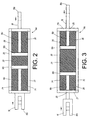
- hitch 14a comprises rigid side walls 20 and end walls 21,21a which contain driving vehicle connecting means 16 and object connecting means 18 in addition to damping medium(s) 22, 24, 26.
- Damping mediums 22, 24, 26 may comprise the same elastomer, or different elastomers, or other damping means, which are disposed in an interactive relationship with connecting means 16 and 18.
- the rigid walls 20 may partially or completely contain the damping medium, depending on the nature of the medium and how much damping is needed.
- Connecting means 16 and 18 are captured by, but not connected to hitch 14a, and are movable with respect to hitch 14a.
- Rod 16c of connecting means 16 passes through hole 23 in end 21 of hitch 14a, and rod 18a passes through hole 25 in opposed end 21a.
- Damping means 24 is disposed between end 21 of hitch 14a and end 16b of connecting means 16, and damping means 26 is disposed between end 21a of hitch 14a and end 18b of the connecting means 18.
- Damping means 22 is disposed between end 16b of connecting means 16 and end 18b of connecting means 18.
- damping means 22, 24, 26 are elastomers, and a tractor is applying a pulling force on connecting means 16, and an implement is resisting movement, elastomers 24 and 26 are in compression, and elastomer 22 is in extension (see Fig. 3), because of forces tending to move end 16b of connecting means 16 in the direction of end 21, and end 18b of connection 18 in the direction of end 21a. Accordingly, elastomers 24 and 26 provide increasing resistance to the movement of ends 16b and 18b the closer they get to ends 21 and 21a, respectively, because of the energy stored in a compressed elastomer that tends to return the elastomer to its original condition.
- Elastomer 22 provides increasing resistance to the movement of connecting means 16 and 18, because of the energy stored by an extended elastomer that tends to return the elastomer to its original state.
- the hitch has a damping effect on the variations of the resistance forces between the drive vehicle and the object, such that it smoothes out the large variation in resistance forces to provide more constant resistance force. Through this more constant resistance force, the occurrence of power hop is minimized or eliminated.
- Power hop has been observed to increase in severity with increased horse power (HP) of the drive vehicle, the use of four wheel drive and radial tires, and a percentage increase in wheel slip.
- HP horse power
- Hitch 14a damps the excessive variations of the forces developed when an agricultural tractor pulls a object (implement), which steadies the hopping of the drive vehicle during movement of the drive vehicle/object combination. This control is achieved by isolating or modulating the frequency variations in the pulled implement, and damping the variations of the resistive force transferred from the implement to the pulling vehicle (tractor).
- springs and /or dampers can be used in place of elastomer to serve the same function as an elastomer.
- springs can be either in compression or tension, while the damper absorbs the energy of excess forces.
- springs 42, 44, 46 are contained within side walls 20a and ends 21, 21a. When a tractor pulls connecting means 16, springs 44 and 46 go into compression, and spring 42 goes into extension, functioning in the same manner discussed above with respect to elastomers 22, 24, 26.
- the hitch 50 may be in the form of a cylinder having ends 21b and tubular side 20b.
- a cylinder has the capability of containing a fluid, preferably a viscous fluid, that is capable of providing a damping function.
- a fluid preferably a viscous fluid
- the hydraulic fluid will absorb some of the excess energies generated by pulling the object.
- hydraulic fluid when channeled as is within the abilities of one in the field of hydraulics, will dampen the energies only, and will provide little or no energy for restoration to a steady state position.
- a hydraulic fluid provides a resistive as well as a damping force. Accordingly, as the connecting means moves to an extreme end of the hitch, resistance increases, and more force is applied by the drive vehicle to the object through the hydraulic fluid. As the object moves in response, the damping action of the fluid permits the return of the connecting means closer to its starting position in the hitch without noticeable loss in the force applied between the drive vehicle and the object, and the hitch is in position to respond to the next variation in resistive force.
- This responsive damping interaction can be enhanced and the equilibrium position of the connecting means in the hitch can be maintained by using an external pressure source, e.g. by attaching the hitch to the tractor?s hydraulic system.
- hitch 60 is shown in the form of a box with sides 20c and 20d and ends 21c.
- the embodiment of Fig. 6 illustrates that the hitch can be made in any convenient shape, as needed or desired for a specific application.
- Hitch 60 can use elastomers, springs and /or dampers, hydraulic fluid, or any other damping means known to those skilled in the art for the damping function.
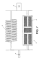
- springs 72 may be used in conjunction with a hydraulic damping means 74 (Fig. 7), to provide a shock absorber type arrangement, to provide the benefits of the spring damping and restoration with the damping benefits of hydraulic action.
- the hitch of the invention may be permanently affixed to the drive vehicle or to the object, or interposed between them whenever connection between them is needed.
Landscapes
- Engineering & Computer Science (AREA)
- Mechanical Engineering (AREA)
- General Engineering & Computer Science (AREA)
- Transportation (AREA)
- Vibration Prevention Devices (AREA)
- Vibration Dampers (AREA)
- Agricultural Machines (AREA)
Abstract
Description
- The invention relates to a hitch for connecting a drive vehicle to an object which is to be moved. The hitch has means for damping forces between the object and the drive vehicle.
- Although the hitch of the invention may be used in a number of various applications, for ease of illustration, the invention will be discussed primarily as it relates to the phenomenon known as power hop. Power hop is a condition of vehicle in which a vehicle (tractor) bounces, primarily in the vertical mode, and causes ride discomfort for the vehicle operator. Power hop occurs when a vehicle (tractor) is pulling an attachment (implement) which applies a significant resistance force to the vehicle. This resistance force of the attachment in the fore-aft (tangential) direction can reach up to 50% to 100% of the vertical load of the vehicle, and is constantly varying. This resistance force of the attachment is referred to as the drawbar load. The variation of these resistance forces contributes to power hop. Power hop can occur on any surface, with any vehicle pulling any sort of object. An agricultural tractor pulling an implement (disk, chisel plow, field cultivator, subsoiler ripper) under soil tillage conditions is one such example.
- It is an object of the invention to provide a device designed to minimize or eliminate the occurrence of power hop by dampening the variation of the resistance forces between the vehicle and its implement, and by isolating or modulating the frequency variations of the drawbar load.
- It often occurs, when a vehicle pulls an object, such as when a truck tractor pulls a trailer, or a farm tractor pulls a plow, or a truck or tractor pulls a tree stump, that forces directly applied by the drive vehicle (tractor), by the drive tires through the hitch connecting the drive vehicle with the object, must overcome an initial large resistance to movement (inertia, friction, surface tension) by the object, i.e., the trailer, plow or tree stump, before the object begins to move. Before the object begins to move, the forces exerted by the drive vehicle are stored as energy somewhere in the drive vehicle or between the drive vehicle and the object. Often, when the resistance is overcome, and the object begins to move, all the stored energy is released in the instant of first movement, and the object lurches or hops ahead, or if the object doesn?t move, the drive vehicle begins to hop.
- It is another object of the present invention to provide a connection means between a drive vehicle and an object that smoothes out the variation of resistive forces in order to reduce or eliminate lurch or hop of an object to be moved, or the hop of a drive vehicle.
- Other objects of the invention will be apparent from the following description and claims.
- The invention relates to a hitch for connecting a drive vehicle (10) to an object to be moved (12). The hitch (14a,40) is characterized by (a) a rigid container made of a rigid material, (b) a first connecting means (16) associated with a first end of the rigid container wherein an exterior portion of the first connecting means has a first end (16a) outside the rigid container and an interior portion (16b) within the rigid container, the first connecting means being movable relative to the rigid container, (c) a second connecting means (18) associated with a second end (21a) of the rigid container wherein an exterior portion of the second connecting means is outside the rigid container and an interior portion (18b) is within the rigid container, and the second connecting means is movable relative to the rigid container, (d) a first resilient means (22, 42) contained within the rigid container between the first and second connecting means, a second resilient means (24, 46) contained within the rigid container between a first end of the rigid container and the first connecting means, and a third resilient means (26, 44) within the rigid container between a second end of the rigid container and the second connecting means.
- In an illustrated embodiment, at least one of the resilient means is elastomeric material, and is preferably rubber.
- In one embodiment, at least one of the resilient means is a spring.
- In a third embodiment, a hydraulic fluid (74) is contained within the container and restricts the movement of the first or second connecting means (16, 18). The hydraulic fluid flows through one or more channels provided in one or both of the interior portions (16b, 18b).
- In a specific embodiment, a hitch (14a) is characterized by (a) a box of rigid material having a cross section having at least two parallel sides (21), (b) a first connecting means (16) is associated with a first end (21b) of the box wherein an exterior portion of the first connecting means is outside the box and an interior portion (16b) is within the box, and the first connecting means is movable relative to the box between the at least two parallel sides, (c) a second connecting means (18) is associated with a second end (21a) of the box wherein an exterior portion of the second connecting means is outside the box and an interior portion (18b) is within the box, and the second connecting means is movable relative to the box between the at least two parallel sides, (d) a first elastomeric material (22) disposed within the box between the first connecting means (16) and the second connecting means (18), (e) a second elastomeric material (24) disposed within the box between the interior portion (16b) of the first connecting means (16) and the box, and (f) a third elastomeric material (26) disposed within the box between the interior portion (18b) of the second connecting means (18) and the box.
- In another specific embodiment a hitch (40) is characterized by (a) a rigid container made of a rigid material, (b) a first connecting means (16) associated with a first end of the rigid container wherein an exterior portion of the first connecting means has a first end (16a) outside the rigid container and an interior portion with a second end (16b) within the rigid container, the first connecting means being movable relative to the rigid container, (c) a second connecting means (18) associated with a second end (21a) of the rigid container wherein an exterior portion of the second connecting means is outside the rigid container and an interior portion (18b) is within the rigid container, and the second connecting means is movable relative to the rigid container, (d) a first spring (42) contained within the rigid container between the first and second connecting means, a second spring (46) contained within the rigid container between a first end of the rigid container and the first connecting means, and a third spring (44) within the rigid container between a second end of the rigid container and the second connecting means.
- In another specific embodiment, the hitch is characterized by (a) a container made of a rigid material, (b) a first connecting means (16) associated with a first end (21b) of the container wherein an exterior portion of the first connecting means is outside the container and an interior portion with a second end (16b) is within the container, and the first connecting means is movable relative to the container,
(c) a second connecting means (18) associated with a second end (21a) of the container wherein an exterior portion of the second connecting means is outside the container and an interior portion with a second end (18b) is within the container, and the second connecting means is movable relative to the container, (d) a hydraulic fluid (74) contained within the container where hydraulic fluid (74) restricts the movement of the fluid and second connecting means (18), and (e) a first spring (42) contained within the rigid container between the first and second connecting means, a second spring (46) contained within the rigid container between a first end of the rigid container and said the connecting means (16), and a third spring (44) within the rigid container between a second end of the rigid container and the second connecting means (18). - The container of the hitch may comprise a cylinder made of a rigid material, wherein the first and second connecting means are associated with opposed ends of the cylinder. A hydraulic fluid may be contained within the cylinder to restrict the movement of the first and second connecting means.
- In another embodiment, the hitch may comprise a rigid container made of a rigid material wherein a first spring is contained within the rigid container between the first and second connecting means, a second spring is contained within the rigid container between a first end of the rigid container and the first connecting means, and a third spring is within the rigid container between a second end of the rigid container and the second connecting means
-
- Fig. 1 illustrates a drive vehicle (a farm tractor) pulling an object (a farm implement known as a subsoiler ripper).
- Figs. 2 and 3 illustrate two different configurations of a representation of the hitch of the invention, illustrating its movements in use.
- Fig. 4 illustrates an alternative construction of the hitch of the invention.
- Fig. 5 illustrates a second alternative construction of the hitch of the invention.
- Fig. 6 illustrates a representation of a possible configuration of the hitch of the invention.
- Fig. 7 illustrates a representation of a spring type dampener in conjunction with a hydraulic dampener.
-
- The invention is directed primarily toward the use of heavy vehicles that are used for pulling attachments with high resistive forces.
- With reference now to Fig. 1, a
driving vehicle 10, illustrated as a farm tractor, is shown pulling anobject 12, illustrated as a subsoiler ripper. Thedriving vehicle 10 is connected to theobject 12 by ahitch 14. Thehitch 14 is connected to the driving vehicle byconnecting means 16, and is connected to theobject 12 by connectingmeans 18. A hitch and its connecting means is typically designed sufficiently robust to transfer forces, required for movement of the object, from the driving vehicle to the object, and is sufficiently flexible in the connection to permit turning and maneuvering of the driving vehicle/object combination, when applicable. - With reference now to Figs. 2 and 3, in a representative embodiment of the invention,
hitch 14a comprisesrigid side walls 20 andend walls vehicle connecting means 16 and object connecting means 18 in addition to damping medium(s) 22, 24, 26.Damping mediums means rigid walls 20 may partially or completely contain the damping medium, depending on the nature of the medium and how much damping is needed. - Connecting means 16 and 18 are captured by, but not connected to hitch 14a, and are movable with respect to hitch 14a.
Rod 16c of connecting means 16 passes through hole 23 inend 21 ofhitch 14a, androd 18a passes throughhole 25 inopposed end 21a. Damping means 24 is disposed betweenend 21 ofhitch 14a andend 16b of connectingmeans 16, and damping means 26 is disposed betweenend 21a ofhitch 14a andend 18b of the connectingmeans 18. Damping means 22 is disposed betweenend 16b of connectingmeans 16 andend 18b of connectingmeans 18. - When damping means 22, 24, 26 are elastomers, and a tractor is applying a pulling force on
connecting means 16, and an implement is resisting movement,elastomers elastomer 22 is in extension (see Fig. 3), because of forces tending to moveend 16b of connectingmeans 16 in the direction ofend 21, andend 18b ofconnection 18 in the direction ofend 21a. Accordingly,elastomers ends ends connecting means - When an agricultural tractor pulls an implement in heavy tillage conditions, and the soil condition and resistance of the soil are such that the resistance forces are at a frequency that is similar to the natural frequency of the drive vehicle, power hop may occur. Power hop has been observed to increase in severity with increased horse power (HP) of the drive vehicle, the use of four wheel drive and radial tires, and a percentage increase in wheel slip.
- Hitch 14a damps the excessive variations of the forces developed when an agricultural tractor pulls a object (implement), which steadies the hopping of the drive vehicle during movement of the drive vehicle/object combination. This control is achieved by isolating or modulating the frequency variations in the pulled implement, and damping the variations of the resistive force transferred from the implement to the pulling vehicle (tractor).
- With reference now to Figs. 4, 5 and 7 in possible embodiments of the invention, springs and /or dampers can be used in place of elastomer to serve the same function as an elastomer. In
hitch 40, springs can be either in compression or tension, while the damper absorbs the energy of excess forces. Inhitch 40springs side walls 20a andends springs spring 42 goes into extension, functioning in the same manner discussed above with respect toelastomers - With reference now to Fig. 5, in a further embodiment, the
hitch 50 may be in the form of acylinder having ends 21b andtubular side 20b. In addition to elastomers or springs, such a cylinder has the capability of containing a fluid, preferably a viscous fluid, that is capable of providing a damping function. For example, if a hydraulic fluid is disposed aroundrods ends means ends means - Those skilled in the art will recognize that hydraulic fluid, when channeled as is within the abilities of one in the field of hydraulics, will dampen the energies only, and will provide little or no energy for restoration to a steady state position.
- A hydraulic fluid provides a resistive as well as a damping force. Accordingly, as the connecting means moves to an extreme end of the hitch, resistance increases, and more force is applied by the drive vehicle to the object through the hydraulic fluid. As the object moves in response, the damping action of the fluid permits the return of the connecting means closer to its starting position in the hitch without noticeable loss in the force applied between the drive vehicle and the object, and the hitch is in position to respond to the next variation in resistive force.
- This responsive damping interaction can be enhanced and the equilibrium position of the connecting means in the hitch can be maintained by using an external pressure source, e.g. by attaching the hitch to the tractor?s hydraulic system.
- With reference now to Fig. 6, hitch 60 is shown in the form of a box with
sides Hitch 60 can use elastomers, springs and /or dampers, hydraulic fluid, or any other damping means known to those skilled in the art for the damping function. In a particularly desirable embodiment inhitch 70, springs 72 may be used in conjunction with a hydraulic damping means 74 (Fig. 7), to provide a shock absorber type arrangement, to provide the benefits of the spring damping and restoration with the damping benefits of hydraulic action. - The hitch of the invention may be permanently affixed to the drive vehicle or to the object, or interposed between them whenever connection between them is needed.
Claims (9)
- A hitch (14a,40) for connecting a driving vehicle (10) to an object (12) to be moved, characterized by(a) a rigid container made of a rigid material,(b) a first connecting means (16) associated with a first end (21b) of said rigid container wherein an exterior portion of said first connecting means has a first end (16a) outside said rigid container and an interior portion (16b) is within said rigid container, said first connecting means being movable relative to said rigid container,(c) a second connecting means (18) associated with a second end (21a) of said rigid container wherein an exterior portion of said second connecting means has a second end (18a) outside said rigid container and an interior portion (18b) is within said rigid container, and said second connecting means is movable relative to said rigid container,(d) a first resilient means (22, 42) contained within said rigid container between said first and second connecting means, a second resilient means (24, 46) contained within said rigid container between a first end (21b) of said rigid container and said first connecting means (16), and a third resilient means (26, 44) within said rigid container between a second end (21a) of said rigid container and said second connecting means (18).
- The hitch of claim 1, wherein at least one of the resilient means is elastomeric material.
- The hitch of claim 2, wherein the elastomeric material is rubber.
- The hitch of any of claims 1-3, wherein at least one of the resilient means is a spring.
- The hitch of any of claims 1-4 wherein a hydraulic fluid (74) contained within said container restricts the movement of the first or second connecting means (16, 18).
- The hitch of claim 5 wherein the hydraulic fluid flows through one or more channels provided in one or both of the interior portions (16b, 18b).
- A hitch (14a) according to claim 1 according to claim 1, characterized by(a) a box of rigid material having a cross section having at least two parallel sides (21),(b) a first connecting means (16) associated with a first end (21b) of said box wherein an exterior portion of said first connecting means is outside said box and an interior portion (16b) is within said box, and said first connecting means is movable relative to said box between said at least two parallel sides,(c) a second connecting means (18) associated with a second end (21a) of said box wherein an exterior portion of said second connecting means is outside said box and an interior portion (18b) is within said box, and said second connecting means is movable relative to said box between said at least two parallel sides,(d) a first elastomeric material (22) disposed within said box between said first connecting means (16) and said second connecting means (18),(e) a second elastomeric material (24) disposed within said box between the interior portion (16b) of said first connecting means (16) and said box, and(f) a third elastomeric material (26) disposed within said box between the interior portion (18b) of said second connecting means (18) and said box.
- A hitch (40) according to claim 1, characterized by(a) a rigid container made of a rigid material,(b) a first connecting means (16) associated with a first end (21b) of said rigid container wherein an exterior portion of said first connecting means has a first end (16a) outside said rigid container and an interior portion with a second end (16b) within said rigid container, said first connecting means being movable relative to said rigid container,(c) a second connecting means (18) associated with a second end (21a) of said rigid container wherein an exterior portion of said second connecting means is outside said rigid container and an interior portion (18b) is within said rigid container, and said second connecting means is movable relative to said rigid container,(d) a first spring (42) contained within said rigid container between said first and second connecting means, a second spring (46) contained within said rigid container between a first end of said rigid container and said first connecting means, and a third spring (44) within said rigid container between a second end of said rigid container and said second connecting means.
- A hitch according to claim 1, characterized by(a) a container made of a rigid material,(b) a first connecting means (16) associated with a first end (21b) of said container wherein an exterior portion of said first connecting means is outside said container and an interior portion with a second end (16b) is within said container, and said first connecting means is movable relative to said container,(c) a second connecting means (18) associated with a second end (21a) of said container wherein an exterior portion of said second connecting means is outside said container and an interior portion with a second end (18b) is within said container, and said second connecting means is movable relative to said container,(d) a hydraulic fluid (74) contained within said container where hydraulic fluid (74) restricts the movement of said fluid and second connecting means (18), and(e) a first spring (42) contained within said rigid container between said first and second connecting means, a second spring (46) contained within said rigid container between a first end of said rigid container and said first connecting means (16), and a third spring (44) within said rigid container between a second end of said rigid container and said second connecting means (18).
Applications Claiming Priority (2)
| Application Number | Priority Date | Filing Date | Title |
|---|---|---|---|
| US09/650,238 US6260873B1 (en) | 2000-08-29 | 2000-08-29 | Isolation hitch |
| US650238 | 2000-08-29 |
Publications (2)
| Publication Number | Publication Date |
|---|---|
| EP1184211A2 true EP1184211A2 (en) | 2002-03-06 |
| EP1184211A3 EP1184211A3 (en) | 2002-11-27 |
Family
ID=24608069
Family Applications (1)
| Application Number | Title | Priority Date | Filing Date |
|---|---|---|---|
| EP01119639A Withdrawn EP1184211A3 (en) | 2000-08-29 | 2001-08-21 | Shock absorbing hitch |
Country Status (3)
| Country | Link |
|---|---|
| US (1) | US6260873B1 (en) |
| EP (1) | EP1184211A3 (en) |
| BR (1) | BR0103446A (en) |
Cited By (1)
| Publication number | Priority date | Publication date | Assignee | Title |
|---|---|---|---|---|
| WO2019148231A1 (en) * | 2018-02-05 | 2019-08-08 | Euler Rolle Thomas | Vibration damper |
Families Citing this family (16)
| Publication number | Priority date | Publication date | Assignee | Title |
|---|---|---|---|---|
| US6834879B1 (en) * | 2002-09-12 | 2004-12-28 | Robin Industries, Inc. | Elastomerically isolated tow hitch drawbar |
| US7354056B2 (en) * | 2003-05-23 | 2008-04-08 | General Motors Corporation | Trailer stability control apparatus |
| US7290783B2 (en) * | 2003-11-21 | 2007-11-06 | Shape Corporation | Towing apparatus with energy absorber |
| US20080221756A1 (en) * | 2007-03-05 | 2008-09-11 | Miskin Mark R | Air suspension to control power hop |
| FR2918840B1 (en) | 2007-07-16 | 2012-07-27 | Michelin Soc Tech | CONNECTION DEVICE BETWEEN A HEAVY VEHICLE AND A TRACT VEHICLE AND TRACTION METHOD. |
| FR2932763B1 (en) * | 2008-06-24 | 2012-05-04 | Michelin Soc Tech | HEAVY VEHICLE FOR TRACTING A GEAR. |
| US8448973B2 (en) | 2010-10-27 | 2013-05-28 | Danny Burns | Trailer hitch apparatus for use with gooseneck trailers |
| US9554559B2 (en) * | 2011-07-29 | 2017-01-31 | JOHN NOLAN McCARTHY | Towed roping dummy shock absorption apparatus |
| US9096105B1 (en) * | 2012-04-30 | 2015-08-04 | Wayne Spiller | Modular trailer hitch buffer |
| US9441696B2 (en) * | 2014-05-29 | 2016-09-13 | Premier Equipment, Inc. | Cushioning system for trailer drawbar |
| CH711440A1 (en) * | 2015-08-21 | 2017-02-28 | Marenco Swisshelicopter Ag | Loader hook construction for attachment to or in a cabin structure of a helicopter. |
| US10493811B2 (en) * | 2018-01-23 | 2019-12-03 | Carl J. Borkholder | AG torsion surge receiver hitch |
| DE102018114100B4 (en) * | 2018-06-13 | 2021-02-11 | Humbaur Gmbh | Overrun device for a vehicle trailer |
| US10787052B2 (en) * | 2018-07-18 | 2020-09-29 | Ford Global Technologies, Llc | Vehicle tow hook |
| CN114248816A (en) * | 2020-09-22 | 2022-03-29 | 湖南中车智行科技有限公司 | Rescue car traction lever device with adjustable buffer strength |
| US20230232735A1 (en) * | 2022-01-26 | 2023-07-27 | Mtd Products Inc | Power equipment machine with foot pedal steering and speed controls |
Family Cites Families (21)
| Publication number | Priority date | Publication date | Assignee | Title |
|---|---|---|---|---|
| US1734072A (en) * | 1927-09-06 | 1929-11-05 | Jacob L Blalack | Towline |
| US1991684A (en) * | 1932-06-13 | 1935-02-19 | Holland Hitch Co | Cushion tow hook |
| US2023527A (en) * | 1934-12-31 | 1935-12-10 | Johansen Hans | Yieldable coupling member |
| US2783039A (en) * | 1954-07-30 | 1957-02-26 | John O Wilson | Trailer hitch shock absorber |
| FR1435779A (en) * | 1964-06-13 | 1966-04-22 | Suspension complex for moving parts | |
| DE1481979A1 (en) * | 1966-09-29 | 1970-03-26 | Krupp Gmbh | Towbar, especially for aircraft |
| US3649048A (en) * | 1969-02-18 | 1972-03-14 | Hunslet Holdings Ltd | Tow-bar assembly |
| DE7130745U (en) * | 1971-08-11 | 1971-12-10 | Ritter H | Tow bar for passenger cars |
| US3881577A (en) * | 1973-08-02 | 1975-05-06 | Toledo Stamping & Mfg | Hitch with trailer brake actuator |
| DE7507902U (en) * | 1975-03-13 | 1975-09-11 | Indulux Waeller & Co | Coupling rods, in particular towing rods for motor vehicles |
| US4085832A (en) * | 1975-05-14 | 1978-04-25 | Gulf & Western Manufacturing Company | Multi-chambered foam energy absorber |
| US4029307A (en) * | 1975-10-28 | 1977-06-14 | Nielson Carl J | Cushioning device |
| NO772853L (en) * | 1976-08-23 | 1978-02-24 | Uni Drive Tractors Ltd | MECHANICAL JOINT CONNECTION. |
| US4114921A (en) * | 1976-09-22 | 1978-09-19 | Thorell Rook O | Vehicle hitch |
| US4506868A (en) * | 1983-05-27 | 1985-03-26 | Sumitomo Metal Industries, Ltd. | Shock absorber for vehicular couplers |
| US4817978A (en) * | 1987-08-24 | 1989-04-04 | James Loyal W | Trailer hitch assemblies |
| US4968010A (en) * | 1988-03-09 | 1990-11-06 | Odobasic Steven Lazar | Slotted disc and elastomeric matrix damper assembly |
| US4978133A (en) * | 1989-10-30 | 1990-12-18 | Thorne Rexford M | Trailer hitch shock absorber |
| US5195768A (en) * | 1991-11-25 | 1993-03-23 | Hendrix William A | Towing hitch ball mount for automatically activating towed vehicle brakes |
| DE4219237A1 (en) * | 1992-06-12 | 1993-12-16 | Heinz Liebmann | Tow-bar between ground vehicle and aircraft - includes linear actuator to ease effects of heavy stationary load on towing vehicle |
| DE29816329U1 (en) * | 1997-09-14 | 1999-04-01 | Holtermann, Konrad, 30419 Hannover | Device for towing motor vehicles |
-
2000
- 2000-08-29 US US09/650,238 patent/US6260873B1/en not_active Expired - Fee Related
-
2001
- 2001-08-21 EP EP01119639A patent/EP1184211A3/en not_active Withdrawn
- 2001-08-21 BR BR0103446-4A patent/BR0103446A/en active Search and Examination
Non-Patent Citations (1)
| Title |
|---|
| None |
Cited By (2)
| Publication number | Priority date | Publication date | Assignee | Title |
|---|---|---|---|---|
| WO2019148231A1 (en) * | 2018-02-05 | 2019-08-08 | Euler Rolle Thomas | Vibration damper |
| US11320015B2 (en) | 2018-02-05 | 2022-05-03 | Thomas Euler-Rolle | Vibration damper |
Also Published As
| Publication number | Publication date |
|---|---|
| US6260873B1 (en) | 2001-07-17 |
| BR0103446A (en) | 2002-04-02 |
| EP1184211A3 (en) | 2002-11-27 |
Similar Documents
| Publication | Publication Date | Title |
|---|---|---|
| US6260873B1 (en) | Isolation hitch | |
| US5378010A (en) | Suspension system for trailer | |
| EP3388297B1 (en) | Vehicle trailer with energy recovery device | |
| US7744149B2 (en) | Cab suspension linkage system | |
| US7934579B2 (en) | Suspension assemblies having resilient member and vehicles including same | |
| JP3148219B2 (en) | Suspension device | |
| US3904226A (en) | Hitch | |
| JP5604518B2 (en) | Equipment for transmitting loads | |
| DE102011100307A1 (en) | Land bound passenger vehicle with a decoupling device and method for decoupling a body of the land-based passenger vehicle | |
| GB1586768A (en) | Rotary cultivators | |
| US5378204A (en) | Hydrostatic apparatus for tensioning a track on a vehicle | |
| CA2159946A1 (en) | Fifth wheel hitch assembly | |
| DE10222309B4 (en) | Forced steering device and trailer vehicle | |
| DE102019104361A1 (en) | DAMPER ASSEMBLY FOR A VEHICLE | |
| WO2008051138A1 (en) | Cab suspension system | |
| JPH05501690A (en) | vehicle | |
| US5711541A (en) | Stabilization apparatus | |
| WO2008051139A1 (en) | Cab suspension system | |
| CA3102652C (en) | Agricultural device | |
| GB2095967A (en) | Pick-up hitch mounting arrangement | |
| AU690084B2 (en) | Stabilization apparatus | |
| RU2397904C1 (en) | Trailed vehicle | |
| US1410313A (en) | Spring support for vehicles | |
| GB2329368A (en) | Towing Hitch | |
| KR100559888B1 (en) | Turning stabilization system of car |
Legal Events
| Date | Code | Title | Description |
|---|---|---|---|
| PUAI | Public reference made under article 153(3) epc to a published international application that has entered the european phase |
Free format text: ORIGINAL CODE: 0009012 |
|
| AK | Designated contracting states |
Kind code of ref document: A2 Designated state(s): AT BE CH CY DE DK ES FI FR GB GR IE IT LI LU MC NL PT SE TR |
|
| AX | Request for extension of the european patent |
Free format text: AL;LT;LV;MK;RO;SI |
|
| PUAL | Search report despatched |
Free format text: ORIGINAL CODE: 0009013 |
|
| AK | Designated contracting states |
Kind code of ref document: A3 Designated state(s): AT BE CH CY DE DK ES FI FR GB GR IE IT LI LU MC NL PT SE TR |
|
| AX | Request for extension of the european patent |
Free format text: AL;LT;LV;MK;RO;SI |
|
| AKX | Designation fees paid | ||
| REG | Reference to a national code |
Ref country code: DE Ref legal event code: 8566 |
|
| STAA | Information on the status of an ep patent application or granted ep patent |
Free format text: STATUS: THE APPLICATION IS DEEMED TO BE WITHDRAWN |
|
| 18D | Application deemed to be withdrawn |
Effective date: 20030528 |