EP1184190A2 - Printer installable in small space - Google Patents
Printer installable in small space Download PDFInfo
- Publication number
- EP1184190A2 EP1184190A2 EP01306987A EP01306987A EP1184190A2 EP 1184190 A2 EP1184190 A2 EP 1184190A2 EP 01306987 A EP01306987 A EP 01306987A EP 01306987 A EP01306987 A EP 01306987A EP 1184190 A2 EP1184190 A2 EP 1184190A2
- Authority
- EP
- European Patent Office
- Prior art keywords
- printer
- cover
- printing head
- printer body
- opening
- Prior art date
- Legal status (The legal status is an assumption and is not a legal conclusion. Google has not performed a legal analysis and makes no representation as to the accuracy of the status listed.)
- Granted
Links
Images



Classifications
-
- B—PERFORMING OPERATIONS; TRANSPORTING
- B41—PRINTING; LINING MACHINES; TYPEWRITERS; STAMPS
- B41J—TYPEWRITERS; SELECTIVE PRINTING MECHANISMS, i.e. MECHANISMS PRINTING OTHERWISE THAN FROM A FORME; CORRECTION OF TYPOGRAPHICAL ERRORS
- B41J29/00—Details of, or accessories for, typewriters or selective printing mechanisms not otherwise provided for
- B41J29/02—Framework
-
- B—PERFORMING OPERATIONS; TRANSPORTING
- B41—PRINTING; LINING MACHINES; TYPEWRITERS; STAMPS
- B41J—TYPEWRITERS; SELECTIVE PRINTING MECHANISMS, i.e. MECHANISMS PRINTING OTHERWISE THAN FROM A FORME; CORRECTION OF TYPOGRAPHICAL ERRORS
- B41J15/00—Devices or arrangements of selective printing mechanisms, e.g. ink-jet printers or thermal printers, specially adapted for supporting or handling copy material in continuous form, e.g. webs
- B41J15/04—Supporting, feeding, or guiding devices; Mountings for web rolls or spindles
- B41J15/042—Supporting, feeding, or guiding devices; Mountings for web rolls or spindles for loading rolled-up continuous copy material into printers, e.g. for replacing a used-up paper roll; Point-of-sale printers with openable casings allowing access to the rolled-up continuous copy material
Definitions
- the present invention relates to a printer for forming predetermined image recording on a recording sheet using a printing head, more specifically, to a printer of a line thermal type installable in a small space.
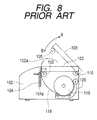
- a printer of this type has a printer body 102 having an opening 102a in its upper portion, a body cover 103 connected to the upper rearward portion of the printer body 102 and pivoted in the direction of arrow A or B to be opened and closed so as to cover the opening 102a, a printing portion 104 for printing and recording letters or photo images on a roll sheet (thermal paper) 119, and a platen roller 105 provided in the front inner portion of the body cover 103 so as to be positioned opposite to a line-like thermal head 104a of the printing portion 104 when the body cover 103 is closed.
- one end side of the body cover 103 is pivotably supported on the printer body 102 through a hinge axis 110.
- the printer 102 is provided with a housing 120, so that a roll sheet 119 is housed rotatably in the housing 120.
- the replacing operation of the roll sheet 119 in the printer will be described below.
- the operator opens the body cover 103.
- the body cover 103 is pivoted in the direction of arrow A.
- the body cover 103 is retained in the opening position by a retaining portion, not shown.
- a new roll sheet 119 is inserted into the housing 120 of the printer body 102 to pivot the body cover 103 in the direction of arrow B.
- the roll sheet 119 is loaded in a predetermined position of the housing 120 of the printer body 102.
- the front end of the roll sheet 119 is pulled and extended out of the printer 102.
- the front end side of the roll sheet 119 is held between the printing portion 104 and the platen roller 105.
- the printer with the roll sheet 119 loaded drives the printing head 104a of the printing portion 104 corresponding to image recording information and rotates the platen roller 105 to print and record the image recording information in a predetermined position of the roll sheet 119.
- Such a prior art printer requires a space for opening and closing the body cover 103 in the upper portion of the printer body 102, and must secure the space.
- the position for installing the printer is limited so that the printer cannot be used in a small place such as a shelf.
- the operator has difficulties in replacing the roll sheet 119.
- An object of the present invention is to provide a printer which requires no excess space for opening and closing a body cover, can be installed in any place, and can be small and thin.
- a printer comprises a printing head provided in a printer body having in its front an opening, wherein a recording medium is inserted into a housing of a cover provided with a platen member, wherein part of the recording medium is placed on the platen member, wherein the cover is inserted from the opening of the printer body into the printer body, wherein and the printing head is resiliently pressed through the recording medium onto the platen member.
- the printing head is provided through a biasing member in the printer body so as to be resiliently pressed onto the platen member provided in the cover by means of the biasing force of the biasing member.
- the printing head presses the cover forward through the platen member by means of the biasing force of the biasing member.
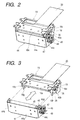
- the printer as shown in its appearance shape of FIG. 1, has a rectangular parallelepiped printer body 12 having in its front an opening 12a, and a cover body 14 slid to the opening 12a of the printer body 12 to be inserted or removed.
- the printer body 12 has a housing 16 of a metal or resin box shape having a hollow interior and a printer body mechanism 18 housed in the housing 16.
- the housing 16 has a bottom plate 16a, a top plate 16b, side plates 16c and 16d, and a back surface 16e, and is surrounded by the bottom plate 16a, the top plate 16b, and the side plates 16c and 16d to form in its front the opening 12a.
- the housing 16 is almost of 1DIN (the German Industrial Standards) size applied to a vehicle-mounted acoustic device.
- the inner walls of the side plates 16c and 16d are respectively formed with guide slots 16g and 16h in parallel with the bottom plate 16a and the top plate 16b and in the front and rear direction.
- the side plate 16c is formed in its forward side corner with a cutout 16k cut away in a rectangular shape.
- the printer body mechanism 18 is made of a sheet metal and has a plate 18a, and side plates 18b and 18c formed by bending both edges of the plate 18a downward at a substantially right angle.
- the plate 18a is formed with a rectangular hole 19 cut away in a rectangular shape.
- the front end of a flexible substrate 20 is drawn outside through the rectangular hole 19.
- the plate 18a is movably provided in its front side (the left side in the figure) through a plurality of coil springs (biasing members) 24, with a head holder 23 disposed between the side plates 18b and 18c and of a rectangular shape in the direction bridging them.
- the head holder 23 is provided in its surface with a line thermal printing head 22 having a plurality of heating elements and is electrically connected to the flexible substrate 20.
- the planer 18a is provided in its rear side (the right side in the figure) with a sheet guide 30 for regulating sheet feeding.
- a photo sensor 32 is disposed in the sheet guide 30 to detect whether or not there is a recording sheet described later.
- the side plates 18b and 18c are respectively provided in the lower end with protruding portions 18e and 18f protruding downward, and in the front side with guide projections 18g and 18h.
- the protruding plate 18e of one side plate 18b is provided with a micro switch 34 to detect that the cover 14 is fitted or removed.
- the other side plate 18c is formed with a stopper strip 36 cut away and cut up.
- an axial portion 38 of metal is supported rotatably.
- Release levers 39 and 40 made of a sheet metal are substantially crank-shaped. One end thereof is provided with lock nail receiving portions 39a and 40a, respectively, and the other end thereof is provided with butting portions 39b and 40b, respectively.
- the respective middle portions of the release levers 39 and 40 are fitted in both ends of the axial portion 38, and are rotatably provided with the side plates 18b and 18c together with the axial portion 38.
- a seizing portion 39c is bent at a substantially right angle.
- a spring member normally retains the butting portion 40b of the release lever 40 to the stopper strip 36 in a biased state.
- the cover body 14 has a drawer-shaped cover member 40 made of metal or resin, and a platen holder 44 mounted in the cover member 40.
- the cover member 40 has a bottom plate 40a, side plates 40b and 40c erected from both side edges of the bottom plate 40a and each having a long, convex-shaped guide projection 41 in the front and rear direction, and a front surface 40d connected integrally to the bottom plate 40a and the side plates 40b and 40c, and provided with a handle 43.
- the upper portion of the cover member 40 is an opening.
- the rear side in the cover member 40 is a housing 40h for housing a recording sheet described later (see FIG. 6C).
- the platen holder 44 has a rectangular-shaped front plate 44a made of a sheet metal, and a pair of side plates 44b and 44c bent rearward from both edges of the front plate 44a.
- the forward side between the side plates 44b and 44c is provided with a cylindrical-shaped platen roller (platen member) 45 of an elastic member such as rubber or metal.
- the platen roller 45 is mounted on a metal shaft 46 rotatably supported on the side plates 44b and 44c.
- the shaft 46 is provided at one end with a gear 47.
- the upper side of the side plate 44b is formed with a lock nail 44e, and the rear side thereof is formed with a pressing portion 44f projecting rearward (the left side in FIG. 5) and having its front end bent at a substantially right angle.
- a driving motor is mounted on the inside of the side plate 44c, and a pinion 48 is mounted on the rotating axis of the driving motor.
- Gears 49 consisting of two gears are engaged with the pinion 48.
- the gears 49 are engaged with the gear 47 to rotatably drive the platen roller 45 by means of the driving force of the driving motor.
- the upper portion of the side plate 44c is formed with a lock nail 44g like the side plate 44b.
- the recording sheet (recording medium) 100 has a width corresponding to the length of the printing head 22 mounted on the head holder 23 and is thermal paper thermally changed and colored by heating the line thermal head as the printing head 22, and wound in a roll form.
- the recording sheet 100 is not limited to the thermal paper, and may be an ordinary or coated sheet according to the kind of the printing head 22 including a thermal method or an ink jetting method.
- the recording sheet 100 is inserted into the opening of the cover member 40 to be housed in the housing 40h of the cover 14.
- the front edge of the recording sheet 100 is pulled out forward to cover the periphery of the platen roller 45.
- the operator grabs the handle 43 so as to slide the cover 40 horizontally rearward while guiding the guide projection 41 of the cover member 40 along the guide slots 16g and 16h of the housing 16.
- the platen roller 45 mounted on the guide member 40 is resiliently pressed onto the printing head 22 of the printer body mechanism 18 against the biasing force of the coil spring (biasing member) 24.
- the lock mails 44e and 44g of the platen holder cover member 40 are respectively hit onto the lock nail receiving portions 39a and 40a of the release levers 39 and 40.
- the release levers 39 and 40 are slightly rotated together with the axial portion 38 against the biasing force of the spring member.
- the lock nail receiving portions 39a and 40a are respectively engaged with the lock nails 44e and 44g for locking.
- the pressing portion 44f of the platen holder 44 is pressed onto the micro switch 34 mounted on the side plate 18b which is then switched ON.
- the micro switch 34 detects that the cover 14 is mounted on the printer body 12 and closed.
- the front end of the recording sheet 100 is resiliently pressed while being held between the printing head 22 and the platen roller 45.
- the front of the pressed portion is formed with an ejection portion 54 for ejecting the recording sheet 100
- the rear of the pressed portion is formed with a sheet carrying path 55 between the partition of the housing 40h and the sheet guide 30.
- the photo sensor 32 detects that the recording sheet 100 is in the sheet carrying path 55.
- the printer body 12 fits the cover 14 so as to load the recording sheet 100.
- the seizing portion 39c of the release lever 39 is pressed in the cutout 16k of the housing 16 rearward (the left side of FIG. 2), the release levers 39 and 40 are pivoted counterclockwise against the spring member, not shown, together with the axial portion 38 to move the lock nail receiving portions 39a and 40a away from the lock nails 44e and 44g.
- the pressing to the micro switch 34 is released to switch it OFF to detect that the locking is released.
- the printing head 22 presses forward the entire cover 14 through the platen roller 45 by means of the biasing force of the coil spring 24.
- the cover 14 is slightly protruded from the opening 12a of the printer body 12.
- the driving force of the driving motor rotates the pinion 48 mounted on the rotating shaft of the driving motor and is then transmitted through the gears 49 and the gear 47 to rotate the platen roller 45.
- the platen roller 45 is rotated to feed the recording sheet 100 housed in the housing 40h in the sheet carrying path 55 onto which is the sheet 100 is image recorded.
- the recording sheet 100 is carried from the ejection portion 54 outside (forward).
- the printer of this embodiment thus constructed and operated has the following effects.
- the printer is described by taking the printer of a line thermal head type as an example. Needles to say, the printer can be applied not only to the thermal printer, but also to various types of printers, facsimiles, and other electronic equipment which slide the cover in the front and rear direction to open it and house a roll sheet in the housing.
- the printer of the present invention described above is provided with a printing head in a printer body having in its front an opening, wherein a recording medium is inserted into a housing of a cover provided with a platen member, wherein part of the recording medium is placed on the platen member, wherein the cover is inserted from the opening of the printer body into the printer body, and wherein the printing head is resiliently pressed through the recording medium onto the platen member.
- the cover can be slid in the front and rear direction to be opened and closed. An opening and closing space is unnecessary in the upper portion of the printer body.
- the printer can be installed in any place to extend the installing range.
Landscapes
- Accessory Devices And Overall Control Thereof (AREA)
- Common Mechanisms (AREA)
- Handling Of Continuous Sheets Of Paper (AREA)
- Unwinding Webs (AREA)
- Handling Of Sheets (AREA)
- Massaging Devices (AREA)
- Particle Formation And Scattering Control In Inkjet Printers (AREA)
Abstract
Description
Claims (3)
- A printer comprising a printing head provided in a printer body having in its front an opening, wherein a recording medium is inserted into a housing of a cover provided with a platen member, wherein part of the recording medium is placed on the platen member, wherein the cover is inserted from the opening of the printer body into the printer body, and wherein the printing head is resiliently pressed through the recording medium onto the platen member.
- The printer according to claim 1, wherein the printing head is provided through a biasing member in the printer body so as to be resiliently pressed onto the platen member provided in the cover by means of the biasing force of the biasing member.
- The printer according to claim 2, wherein the printing head presses the cover forward through the platen member by means of the biasing force of the biasing member.
Applications Claiming Priority (2)
| Application Number | Priority Date | Filing Date | Title |
|---|---|---|---|
| JP2000268401A JP2002067435A (en) | 2000-08-31 | 2000-08-31 | Printer |
| JP2000268401 | 2000-08-31 |
Publications (3)
| Publication Number | Publication Date |
|---|---|
| EP1184190A2 true EP1184190A2 (en) | 2002-03-06 |
| EP1184190A3 EP1184190A3 (en) | 2003-03-19 |
| EP1184190B1 EP1184190B1 (en) | 2006-12-27 |
Family
ID=18755185
Family Applications (1)
| Application Number | Title | Priority Date | Filing Date |
|---|---|---|---|
| EP01306987A Expired - Lifetime EP1184190B1 (en) | 2000-08-31 | 2001-08-17 | Printer installable in small space |
Country Status (7)
| Country | Link |
|---|---|
| US (1) | US6414704B1 (en) |
| EP (1) | EP1184190B1 (en) |
| JP (1) | JP2002067435A (en) |
| CN (1) | CN1170691C (en) |
| AT (1) | ATE349333T1 (en) |
| DE (1) | DE60125476T2 (en) |
| TW (1) | TW549242U (en) |
Families Citing this family (29)
| Publication number | Priority date | Publication date | Assignee | Title |
|---|---|---|---|---|
| EP1232612B1 (en) * | 1999-11-18 | 2006-11-02 | Broadcom Corporation | Table lookup mechanism for address resolution in a packet network switch |
| DE10215122B4 (en) * | 2002-04-05 | 2005-03-03 | Siemens Ag | Tachograph with a cuboidal housing and a printing device |
| US7254632B2 (en) * | 2002-04-26 | 2007-08-07 | P-Cube Ltd. | Apparatus and method for pattern matching in text based protocol |
| DE10321233A1 (en) * | 2003-05-12 | 2004-12-09 | Siemens Ag | printer |
| DE10321225B4 (en) * | 2003-05-12 | 2005-03-03 | Siemens Ag | printer |
| DE10321248A1 (en) * | 2003-05-12 | 2004-12-09 | Siemens Ag | connection |
| US20050151762A1 (en) * | 2004-01-14 | 2005-07-14 | Griesemer Frederick C. | Image recording apparatus with slidably opening scanner bed |
| US7287850B2 (en) * | 2004-01-22 | 2007-10-30 | Casio Computer Co., Ltd. | Portable electronic apparatus |
| JP4582337B2 (en) * | 2006-02-24 | 2010-11-17 | セイコーエプソン株式会社 | Electronic equipment, recording device, liquid ejecting device |
| JP5041046B2 (en) * | 2010-09-30 | 2012-10-03 | ブラザー工業株式会社 | Recording device |
| JP5364738B2 (en) * | 2011-02-18 | 2013-12-11 | シチズンホールディングス株式会社 | Thermal printer |
| EP2586617B1 (en) | 2011-10-31 | 2014-09-24 | Brother Kogyo Kabushiki Kaisha | Recording apparatus with recording-medium conveying mechanism |
| US8767065B2 (en) | 2011-10-31 | 2014-07-01 | Brother Kogyo Kabushiki Kaisha | Recording apparatus having liquid supply system |
| EP2599635B1 (en) | 2011-11-30 | 2014-11-05 | Brother Kogyo Kabushiki Kaisha | Liquid ejecting device |
| US8708482B2 (en) | 2011-11-30 | 2014-04-29 | Brother Kogyo Kabushiki Kaisha | Liquid ejecting device |
| JP6094200B2 (en) * | 2012-12-17 | 2017-03-15 | セイコーエプソン株式会社 | Conveying apparatus and recording apparatus |
| JP6145375B2 (en) | 2013-09-27 | 2017-06-14 | セイコーインスツル株式会社 | Thermal printer |
| CN107097539B (en) * | 2013-11-12 | 2019-12-31 | 精工爱普生株式会社 | printer |
| JP2015202566A (en) * | 2014-04-10 | 2015-11-16 | サトーホールディングス株式会社 | printer |
| JP6578099B2 (en) * | 2014-12-25 | 2019-09-18 | サトーホールディングス株式会社 | Printer |
| JP2016203382A (en) | 2015-04-15 | 2016-12-08 | 富士通コンポーネント株式会社 | Printer |
| DE102016101137A1 (en) * | 2016-01-22 | 2017-07-27 | Phoenix Contact Gmbh & Co. Kg | Printer for printing on print objects and ribbon cassette for use with a printer |
| JP6686713B2 (en) * | 2016-06-09 | 2020-04-22 | ブラザー工業株式会社 | Printer |
| JP7178279B2 (en) * | 2019-01-29 | 2022-11-25 | 富士通コンポーネント株式会社 | printer device |
| JP7230577B2 (en) * | 2019-02-21 | 2023-03-01 | セイコーエプソン株式会社 | Conveyor and recording device |
| JP7309402B2 (en) * | 2019-03-26 | 2023-07-18 | 理想科学工業株式会社 | image forming device |
| JP7287818B2 (en) * | 2019-03-29 | 2023-06-06 | 富士通コンポーネント株式会社 | printer device |
| JP7294038B2 (en) * | 2019-09-30 | 2023-06-20 | ブラザー工業株式会社 | Paper feed unit |
| US20250206035A1 (en) * | 2022-03-07 | 2025-06-26 | Koninklijke Philips N.V. | Printing mechanism for medical monitoring device and medical monitoring device |
Family Cites Families (5)
| Publication number | Priority date | Publication date | Assignee | Title |
|---|---|---|---|---|
| EP0183356B1 (en) * | 1984-10-02 | 1991-07-03 | Fujitsu Limited | Front-loading paper feed for a printer |
| JPH01127851A (en) | 1987-11-13 | 1989-05-19 | Sharp Corp | Air conditioning device |
| JP2963246B2 (en) * | 1991-09-06 | 1999-10-18 | ローム株式会社 | Thermal transfer printer |
| JPH1178146A (en) * | 1997-09-02 | 1999-03-23 | Fuji Photo Film Co Ltd | Printer |
| JP3908449B2 (en) * | 2000-08-25 | 2007-04-25 | セイコーインスツル株式会社 | Drawer type line thermal printer |
-
2000
- 2000-08-31 JP JP2000268401A patent/JP2002067435A/en not_active Withdrawn
-
2001
- 2001-08-01 TW TW091219144U patent/TW549242U/en not_active IP Right Cessation
- 2001-08-16 CN CNB011306300A patent/CN1170691C/en not_active Expired - Fee Related
- 2001-08-17 AT AT01306987T patent/ATE349333T1/en not_active IP Right Cessation
- 2001-08-17 EP EP01306987A patent/EP1184190B1/en not_active Expired - Lifetime
- 2001-08-17 DE DE60125476T patent/DE60125476T2/en not_active Expired - Lifetime
- 2001-08-22 US US09/934,760 patent/US6414704B1/en not_active Expired - Fee Related
Also Published As
| Publication number | Publication date |
|---|---|
| CN1170691C (en) | 2004-10-13 |
| JP2002067435A (en) | 2002-03-05 |
| EP1184190B1 (en) | 2006-12-27 |
| EP1184190A3 (en) | 2003-03-19 |
| US6414704B1 (en) | 2002-07-02 |
| DE60125476T2 (en) | 2007-10-04 |
| TW549242U (en) | 2003-08-21 |
| DE60125476D1 (en) | 2007-02-08 |
| US20020024578A1 (en) | 2002-02-28 |
| CN1340420A (en) | 2002-03-20 |
| ATE349333T1 (en) | 2007-01-15 |
Similar Documents
| Publication | Publication Date | Title |
|---|---|---|
| EP1184190B1 (en) | Printer installable in small space | |
| EP1918117B1 (en) | Rolled sheet support mechanism and printer | |
| CN102689522B (en) | printer | |
| US5645360A (en) | Tape cassette used in tape printing apparatus | |
| US11712909B2 (en) | Cutting device including cutter lever for moving cutter blade, and cutter cradle lever for moving both cutter blade and cutter cradle | |
| JP2011104674A (en) | Sheet cutter and printer employing the same | |
| CN102120389B (en) | Recording device and recording medium supply mechanism for a recording device | |
| US11654701B2 (en) | Cutting device including first lever and second lever for moving cutter blade and cutter cradle to perform cutting operation with respect to cut target | |
| GB2289867A (en) | Thermal printer | |
| JPH10193710A (en) | Printer | |
| JP4898616B2 (en) | Roll paper accommodation mechanism and printer | |
| JP3617146B2 (en) | Printing device | |
| CN204222391U (en) | Thermal printer | |
| US6764237B2 (en) | Printer with cutter device | |
| US5615960A (en) | Tape printing apparatus having a slot for insertion of a tape cassette | |
| JP3724414B2 (en) | Printer device | |
| JP3741952B2 (en) | Printer | |
| JP2005028621A (en) | Printer device | |
| JP4338622B2 (en) | Paper misinsertion prevention mechanism | |
| JP7323863B2 (en) | MEDIUM CONVEYING DEVICE, POST-PROCESSING DEVICE AND RECORDING DEVICE | |
| JP2005254620A (en) | Printer | |
| JP4612898B2 (en) | Sheet feeding apparatus, image recording apparatus, and image reading apparatus | |
| JPH05147314A (en) | Printer | |
| JPH11314813A (en) | Printer device | |
| JP6443286B2 (en) | Electronics |
Legal Events
| Date | Code | Title | Description |
|---|---|---|---|
| PUAI | Public reference made under article 153(3) epc to a published international application that has entered the european phase |
Free format text: ORIGINAL CODE: 0009012 |
|
| AK | Designated contracting states |
Kind code of ref document: A2 Designated state(s): AT BE CH CY DE DK ES FI FR GB GR IE IT LI LU MC NL PT SE TR |
|
| AX | Request for extension of the european patent |
Free format text: AL;LT;LV;MK;RO;SI |
|
| PUAL | Search report despatched |
Free format text: ORIGINAL CODE: 0009013 |
|
| AK | Designated contracting states |
Kind code of ref document: A3 Designated state(s): AT BE CH CY DE DK ES FI FR GB GR IE IT LI LU MC NL PT SE TR |
|
| AX | Request for extension of the european patent |
Extension state: AL LT LV MK RO SI |
|
| 17P | Request for examination filed |
Effective date: 20030326 |
|
| AKX | Designation fees paid |
Designated state(s): AT BE CH CY DE DK ES FI FR GB GR IE IT LI LU MC NL PT SE TR |
|
| GRAP | Despatch of communication of intention to grant a patent |
Free format text: ORIGINAL CODE: EPIDOSNIGR1 |
|
| GRAS | Grant fee paid |
Free format text: ORIGINAL CODE: EPIDOSNIGR3 |
|
| GRAA | (expected) grant |
Free format text: ORIGINAL CODE: 0009210 |
|
| AK | Designated contracting states |
Kind code of ref document: B1 Designated state(s): AT BE CH CY DE DK ES FI FR GB GR IE IT LI LU MC NL PT SE TR |
|
| PG25 | Lapsed in a contracting state [announced via postgrant information from national office to epo] |
Ref country code: IT Free format text: LAPSE BECAUSE OF FAILURE TO SUBMIT A TRANSLATION OF THE DESCRIPTION OR TO PAY THE FEE WITHIN THE PRESCRIBED TIME-LIMIT;WARNING: LAPSES OF ITALIAN PATENTS WITH EFFECTIVE DATE BEFORE 2007 MAY HAVE OCCURRED AT ANY TIME BEFORE 2007. THE CORRECT EFFECTIVE DATE MAY BE DIFFERENT FROM THE ONE RECORDED. Effective date: 20061227 Ref country code: FI Free format text: LAPSE BECAUSE OF FAILURE TO SUBMIT A TRANSLATION OF THE DESCRIPTION OR TO PAY THE FEE WITHIN THE PRESCRIBED TIME-LIMIT Effective date: 20061227 Ref country code: AT Free format text: LAPSE BECAUSE OF FAILURE TO SUBMIT A TRANSLATION OF THE DESCRIPTION OR TO PAY THE FEE WITHIN THE PRESCRIBED TIME-LIMIT Effective date: 20061227 Ref country code: DK Free format text: LAPSE BECAUSE OF FAILURE TO SUBMIT A TRANSLATION OF THE DESCRIPTION OR TO PAY THE FEE WITHIN THE PRESCRIBED TIME-LIMIT Effective date: 20061227 Ref country code: NL Free format text: LAPSE BECAUSE OF FAILURE TO SUBMIT A TRANSLATION OF THE DESCRIPTION OR TO PAY THE FEE WITHIN THE PRESCRIBED TIME-LIMIT Effective date: 20061227 Ref country code: LI Free format text: LAPSE BECAUSE OF FAILURE TO SUBMIT A TRANSLATION OF THE DESCRIPTION OR TO PAY THE FEE WITHIN THE PRESCRIBED TIME-LIMIT Effective date: 20061227 Ref country code: BE Free format text: LAPSE BECAUSE OF FAILURE TO SUBMIT A TRANSLATION OF THE DESCRIPTION OR TO PAY THE FEE WITHIN THE PRESCRIBED TIME-LIMIT Effective date: 20061227 Ref country code: CH Free format text: LAPSE BECAUSE OF FAILURE TO SUBMIT A TRANSLATION OF THE DESCRIPTION OR TO PAY THE FEE WITHIN THE PRESCRIBED TIME-LIMIT Effective date: 20061227 |
|
| REG | Reference to a national code |
Ref country code: GB Ref legal event code: FG4D |
|
| REG | Reference to a national code |
Ref country code: IE Ref legal event code: FG4D |
|
| REF | Corresponds to: |
Ref document number: 60125476 Country of ref document: DE Date of ref document: 20070208 Kind code of ref document: P |
|
| PG25 | Lapsed in a contracting state [announced via postgrant information from national office to epo] |
Ref country code: SE Free format text: LAPSE BECAUSE OF FAILURE TO SUBMIT A TRANSLATION OF THE DESCRIPTION OR TO PAY THE FEE WITHIN THE PRESCRIBED TIME-LIMIT Effective date: 20070327 |
|
| PG25 | Lapsed in a contracting state [announced via postgrant information from national office to epo] |
Ref country code: ES Free format text: LAPSE BECAUSE OF FAILURE TO SUBMIT A TRANSLATION OF THE DESCRIPTION OR TO PAY THE FEE WITHIN THE PRESCRIBED TIME-LIMIT Effective date: 20070407 |
|
| PG25 | Lapsed in a contracting state [announced via postgrant information from national office to epo] |
Ref country code: PT Free format text: LAPSE BECAUSE OF FAILURE TO SUBMIT A TRANSLATION OF THE DESCRIPTION OR TO PAY THE FEE WITHIN THE PRESCRIBED TIME-LIMIT Effective date: 20070528 |
|
| NLV1 | Nl: lapsed or annulled due to failure to fulfill the requirements of art. 29p and 29m of the patents act | ||
| REG | Reference to a national code |
Ref country code: CH Ref legal event code: PL |
|
| ET | Fr: translation filed | ||
| PLBE | No opposition filed within time limit |
Free format text: ORIGINAL CODE: 0009261 |
|
| STAA | Information on the status of an ep patent application or granted ep patent |
Free format text: STATUS: NO OPPOSITION FILED WITHIN TIME LIMIT |
|
| 26N | No opposition filed |
Effective date: 20070928 |
|
| PG25 | Lapsed in a contracting state [announced via postgrant information from national office to epo] |
Ref country code: GR Free format text: LAPSE BECAUSE OF FAILURE TO SUBMIT A TRANSLATION OF THE DESCRIPTION OR TO PAY THE FEE WITHIN THE PRESCRIBED TIME-LIMIT Effective date: 20070328 Ref country code: MC Free format text: LAPSE BECAUSE OF NON-PAYMENT OF DUE FEES Effective date: 20070831 |
|
| PG25 | Lapsed in a contracting state [announced via postgrant information from national office to epo] |
Ref country code: IE Free format text: LAPSE BECAUSE OF NON-PAYMENT OF DUE FEES Effective date: 20070817 |
|
| PG25 | Lapsed in a contracting state [announced via postgrant information from national office to epo] |
Ref country code: CY Free format text: LAPSE BECAUSE OF FAILURE TO SUBMIT A TRANSLATION OF THE DESCRIPTION OR TO PAY THE FEE WITHIN THE PRESCRIBED TIME-LIMIT Effective date: 20061227 Ref country code: LU Free format text: LAPSE BECAUSE OF NON-PAYMENT OF DUE FEES Effective date: 20070817 |
|
| PG25 | Lapsed in a contracting state [announced via postgrant information from national office to epo] |
Ref country code: TR Free format text: LAPSE BECAUSE OF FAILURE TO SUBMIT A TRANSLATION OF THE DESCRIPTION OR TO PAY THE FEE WITHIN THE PRESCRIBED TIME-LIMIT Effective date: 20061227 |
|
| PGFP | Annual fee paid to national office [announced via postgrant information from national office to epo] |
Ref country code: FR Payment date: 20090806 Year of fee payment: 9 |
|
| REG | Reference to a national code |
Ref country code: FR Ref legal event code: ST Effective date: 20110502 |
|
| PG25 | Lapsed in a contracting state [announced via postgrant information from national office to epo] |
Ref country code: FR Free format text: LAPSE BECAUSE OF NON-PAYMENT OF DUE FEES Effective date: 20100831 |
|
| PGFP | Annual fee paid to national office [announced via postgrant information from national office to epo] |
Ref country code: GB Payment date: 20110722 Year of fee payment: 11 Ref country code: DE Payment date: 20110831 Year of fee payment: 11 |
|
| GBPC | Gb: european patent ceased through non-payment of renewal fee |
Effective date: 20120817 |
|
| PG25 | Lapsed in a contracting state [announced via postgrant information from national office to epo] |
Ref country code: DE Free format text: LAPSE BECAUSE OF NON-PAYMENT OF DUE FEES Effective date: 20130301 Ref country code: GB Free format text: LAPSE BECAUSE OF NON-PAYMENT OF DUE FEES Effective date: 20120817 |
|
| REG | Reference to a national code |
Ref country code: DE Ref legal event code: R119 Ref document number: 60125476 Country of ref document: DE Effective date: 20130301 |