EP1184095A2 - Method and apparatus for interchanging ring rolls of a bar and wire rod mill - Google Patents
Method and apparatus for interchanging ring rolls of a bar and wire rod mill Download PDFInfo
- Publication number
- EP1184095A2 EP1184095A2 EP01304161A EP01304161A EP1184095A2 EP 1184095 A2 EP1184095 A2 EP 1184095A2 EP 01304161 A EP01304161 A EP 01304161A EP 01304161 A EP01304161 A EP 01304161A EP 1184095 A2 EP1184095 A2 EP 1184095A2
- Authority
- EP
- European Patent Office
- Prior art keywords
- roll
- roll shaft
- ring
- hydraulic oil
- housing
- Prior art date
- Legal status (The legal status is an assumption and is not a legal conclusion. Google has not performed a legal analysis and makes no representation as to the accuracy of the status listed.)
- Withdrawn
Links
- 238000000034 method Methods 0.000 title claims abstract description 28
- 230000000712 assembly Effects 0.000 claims abstract description 10
- 238000000429 assembly Methods 0.000 claims abstract description 10
- 239000003921 oil Substances 0.000 claims description 37
- 239000010720 hydraulic oil Substances 0.000 claims description 31
- 239000000725 suspension Substances 0.000 claims description 13
- 230000008878 coupling Effects 0.000 claims 1
- 238000010168 coupling process Methods 0.000 claims 1
- 238000005859 coupling reaction Methods 0.000 claims 1
- 238000002347 injection Methods 0.000 description 14
- 239000007924 injection Substances 0.000 description 14
- 230000035939 shock Effects 0.000 description 6
- 238000005096 rolling process Methods 0.000 description 3
- 229910000831 Steel Inorganic materials 0.000 description 2
- 238000010276 construction Methods 0.000 description 2
- 230000003247 decreasing effect Effects 0.000 description 2
- 230000000694 effects Effects 0.000 description 2
- 239000000463 material Substances 0.000 description 2
- 230000002093 peripheral effect Effects 0.000 description 2
- 238000004513 sizing Methods 0.000 description 2
- 239000010959 steel Substances 0.000 description 2
- 238000005299 abrasion Methods 0.000 description 1
- 239000002131 composite material Substances 0.000 description 1
- 230000006835 compression Effects 0.000 description 1
- 238000007906 compression Methods 0.000 description 1
- 238000007796 conventional method Methods 0.000 description 1
- 239000000428 dust Substances 0.000 description 1
- 238000005098 hot rolling Methods 0.000 description 1
- 230000009545 invasion Effects 0.000 description 1
- 230000033001 locomotion Effects 0.000 description 1
- 238000002360 preparation method Methods 0.000 description 1
- 238000003860 storage Methods 0.000 description 1
Images



Classifications
-
- B—PERFORMING OPERATIONS; TRANSPORTING
- B21—MECHANICAL METAL-WORKING WITHOUT ESSENTIALLY REMOVING MATERIAL; PUNCHING METAL
- B21B—ROLLING OF METAL
- B21B31/00—Rolling stand structures; Mounting, adjusting, or interchanging rolls, roll mountings, or stand frames
- B21B31/08—Interchanging rolls, roll mountings, or stand frames, e.g. using C-hooks; Replacing roll chocks on roll shafts
-
- B—PERFORMING OPERATIONS; TRANSPORTING
- B21—MECHANICAL METAL-WORKING WITHOUT ESSENTIALLY REMOVING MATERIAL; PUNCHING METAL
- B21B—ROLLING OF METAL
- B21B13/00—Metal-rolling stands, i.e. an assembly composed of a stand frame, rolls, and accessories
- B21B13/08—Metal-rolling stands, i.e. an assembly composed of a stand frame, rolls, and accessories with differently-directed roll axes, e.g. for the so-called "universal" rolling process
- B21B13/10—Metal-rolling stands, i.e. an assembly composed of a stand frame, rolls, and accessories with differently-directed roll axes, e.g. for the so-called "universal" rolling process all axes being arranged in one plane
- B21B13/103—Metal-rolling stands, i.e. an assembly composed of a stand frame, rolls, and accessories with differently-directed roll axes, e.g. for the so-called "universal" rolling process all axes being arranged in one plane for rolling bars, rods or wire
Definitions
- the present invention relates to a method and apparatus for changing ring rolls of a bar and wire rod mill which makes roll changing work easy.
- the apparatus for changing ring rolls comprises a main body of a bar roll mill having a roll changing mechanism and a roll shaft suspending apparatus.
- a plurality of sizing mills are arranged in the final stage of a continuous rolling mill line for hot-rolling steel materials into bar and/or wire rods.
- a bar and wire rod mill is provided in which a plurality of roll assemblies supported by housings are arranged in equiangular positions around the pass line.
- the roll assembly it comprises a composite structure having ring rolls in contact with rolling materials and a roll shaft fitted into the bore of the ring rolls to support it.
- Japanese Patent Laid-Open No. 104706/1999 discloses a bar and wire rod mill with a construction facilitating the changing operation of the ring rolls.
- This kind of roll mill has a plurality of roll units and a draft adjusting apparatus of an eccentric cartridge type for a roll unit mounted on the housing.
- the roll unit is synonymous with the roll assembly.
- the housing consists of two pieces including first and second housing parts capable of engaging with, and disengaging from, each other.
- a pair of journal bearing halves are formed in the contact face of the first and second housing parts.
- the journal part of each roll unit held in an eccentric cartridge is sandwiched between the engaged journal bearing halves of the first and second housing parts.
- the roll changing operation of this bar and wire rod mill is performed as follows:
- the roll changing operation is made easy because the roll mill can be disassembled and re-assembled through only a few steps.
- a method of roll changing which can resolve these problems, and a main body of a bar and wire rod mill and its peripheral apparatus advantageous for performing such a method, are desired.
- the inventors have developed a method for changing only the ring rolls without disassembling the housing, and found a roll changing method comprising an optimum sequence of steps.
- the inventors have developed a main body of a bar and wire rod mill comprising a mechanism for changing only the ring rolls without disassembling the housing, and a roll shaft suspending apparatus capable of dual-use for applying hydraulic oil pressure, required for engaging or disengaging the ring rolls and the roll shaft in interference fit, and for suspending the roll shaft, which is suitable for the roll changing method of the invention.
- the present invention relates to a method for changing ring rolls used in a bar and wire rod mill having a plurality of roll assemblies incorporated into a pair of housings and arranged in equiangular positions around the pass formed by the ring rolls as shown in Fig. 1, comprising the steps of disengaging the interference fit between the spent ring rolls and roll shaft, withdrawing the roll shaft from the spent ring rolls by lifting-up the roll shaft in an axial direction, changing the spent ring rolls for new ring rolls in said housings, inserting the roll shaft into the new ring rolls, and engaging the new ring rolls with the roll shaft in interference fit.
- the present invention relates to a bar and wire rod mill suitable for applying the aforesaid method for changing ring rolls, in which a plurality of roll assemblies supported by a housing, comprising ring rolls capable of engaging with and disengaging from the roll shaft in interference fit and the roll shafts movable in an axial direction in a housing, are arranged in equiangular positions around the pass formed by these ring rolls.
- the roll shaft can be withdrawn from the ring rolls by means of a pushing or pulling action of the roll shaft which is grasped at the end thereof.
- the roll shaft is inserted into the new ring rolls and engaged therewith by interference fit.
- the roll assembly it is preferable for the roll assembly to equip with a mechanism for engaging or disengaging the ring rolls and the roll shaft in and from interference fit by the use of hydraulic oil pressure, a hydraulic oil passage being provided through the roll shaft from the end thereof and an oil inlet and a suspension jig receiving member both being provided on one end portion of the roll shaft. Furthermore, it is preferable for the internal surface of the ring roll and the journal part of the roll shaft for the ring roll of the roll assemblies to form tapered surfaces.
- the roll shaft can be engaged with, or disengaged from, the ring rolls in interference fit by applying hydraulic oil pressure through the oil passage inside the roll shaft from the end thereof to make both tapered surfaces either engaged in tight contact fit or disengaged from each other. Furthermore, as the journal part of the roll shaft for the ring rolls and the ring rolls are engaged or disengaged through the tapered surface, the interference fit can be made firm to a greater extent and the disengagement can be made smooth to a greater degree due to the wedge effect of the tapered surface.
- both tapered surfaces can be engaged or disengaged freely by applying hydraulic oil pressure from outside the housing successively to all of the roll assembly.
- all of the multiple roll assembly can be of the motor driven type or some of them may be motor driven while others are not.
- the bar and wire rod mill according to the present invention may preferably be a four-roll mill comprising four pieces of roll assembly, supported by a housing arranged in equiangular positions around a pass formed by four rolls as shown in Fig. 1
- embodiments of the present invention relate to a roll shaft suspending apparatus suitable for use in the method for changing ring rolls as disclosed, comprising a nozzle for injecting hydraulic oil into the oil inlet provided on one end of the roll shaft, a rod holding the nozzle at the top end thereof and an internal oil feed passage connected to the nozzle through the rod, a cylinder embracing the rod for reciprocal actuation by means of hydraulic oil pressure, and a front end of a rod suspending apparatus engaged with the suspension jig receiving member provided on one end of the roll shaft. It may be further preferable to provide a mechanism by which the rod holds the nozzle through a resilient seat.
- a more steady and quick change of the roll is made possible by applying the roll shaft suspending apparatus in accordance with the method of the invention. It is performed according to the following operation in which the roll shaft of the roll assembly with the roll to be changed is set in an upright position before disengaging the spent ring rolls from the interference fit with the roll shaft, and then the suspending apparatus and one end portion of the roll shaft are coupled together before withdrawing the roll shaft from the spent ring rolls so as to connect the hydraulic piping inside the roll shaft with the hydraulic oil pressure source via the one end portion of the roll shaft.
- Fig. 1 is a cross-sectional view showing the main part of the structure of the four-roll mill according to the present invention.
- Fig. 1 a quarter portion centered around the pass 16 is illustrated. The whole view can be obtained from the combination of each rotated view of Fig. 1 by 90°, 180° and 270°.
- the roll assembly is constructed by attaching a ring roll 2 to the journal part 1A located in the lower side of a roll shaft 1.
- the outer circumferential surface of the ring roll 2 is configured as the working surface of the roll.
- Both of the outer circumferential surface of the journal part 1A, which is an engagement part of the roll shaft 1 and the ring roll 2, and the internal surface of the ring roll 2 have a tapered surface, and both tapered parts are engaged together in interference fit.
- the outer circumferential surface of the journal part 1A is a tapered male surface having upward inclination toward the upper end of the roll shaft 1.
- the engagement or the disengagement of the roll shaft 1 and the ring roll 2 in interference fit is performed by engaging or disengaging the male and female tapered surfaces by means of, for example, applied hydraulic oil pressure.
- Bearings 4A and 4B are mounted on respective positions opposite to each other across the ring journal part 1A of the lower portion of the roll shaft 1, and a bearing 5 is mounted on a position of the upper portion thereof.
- the lower portion bearings 4A and 4B are supported by a housing 8 through a lower eccentric cartridge 6A.
- the upper portion bearing 5 is supported by a housing 8 through an upper eccentric cartridge 6B and a thrust adjusting screw 7. Incidentally, the upper end portion of the roll shaft is exposed outside the housing 8.
- the lower eccentric cartridge 6A supports the bearing 4A, 4B and the upper eccentric cartridge 6B supports the bearing 5 slidably along the axial direction of the roll, respectively.
- the lower eccentric cartridge 6A and the upper eccentric cartridge 6B that can rotate around their own shaft, are supported by the housing 8.
- the center of the roll shaft 1 rotates around the center of the lower eccentric cartridge 6A.
- the upper eccentric cartridge is also rotated likewise.
- the eccentric cartridge 6 moves the roll shaft 1 along the direction perpendicular thereto so that it is used for the adjustment of the distance from the center of the ring roll 2 to the center of the pass, namely the rolling position.
- the lower eccentric cartridge 6A and the upper eccentric cartridge 6B are interconnected to each other and the distance between them can be varied.
- the bearing 5 is held by a fastening screw 9 to the upper eccentric cartridge 6B.
- the external diameter of the bearing 4A and 4B is set to be less than the internal diameter of the tapered sleeve 3 so as to disengage the tapered surface of the roll shaft 1 and the ring roll 2 from each other. Further, the fastening screw 9 is disengaged to move the roll shaft 1 along the axial direction thereof. As a result, the roll shaft 1 can be withdrawn from the ring roll 2.
- the thrust adjusting screw 7 supports the upper eccentric cartridge 6B with its inner peripheral surface so as to rotate around its own shaft.
- the thrust adjusting screw 7 is engaged by means of a thread on its periphery with the screw receiving member 10 which is held by a screw to the housing 8.
- the thrust adjusting screw 7 is connected to the screw receiving member 10 by means of a clamp bolt 11. Therefore, by loosening the clamp bolt 11 and driving the thrust adjusting screw 7, the position of the roll assembly along the axial direction of the roll can be adjusted.
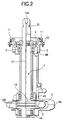
- Fig. 2 is a cross-sectional view showing a means for applying hydraulic oil pressure to the tapered surfaces.
- An oil feed passage 12 extends through the inside of the roll shaft from an oil inlet 12A in the end face of the roll shaft to an oil outlet 12B.
- the end portion of the roll shaft where the oil inlet 12A opens is extended outside of the housing, and a circumferential groove 22 is provided on the extended end portion of the roll shaft.
- the circumferential groove 22 serves as a receiving part for the suspension jig when suspending the roll shaft 1.
- the oil outlet 12B opens at a plurality of positions over the tapered surface of the journal part 1A of the ring.
- the injection of high pressure oil from the oil inlet 12A makes the internal diameter of the tapered sleeve 3 expand within its elastic limit by means of the hydraulic oil pressure from the oil inlet 12A.
- a counter force is generated between the two tapered surfaces to facilitate their disengagement from each other.
- the hydraulic oil pressure is decreased and when the inside diameter is restored to its original size, both tapered surfaces are left in a disengaged condition. Consequently, the roll shaft 1 can be withdrawn out of the ring roll 2 by pulling it toward the outside of the housing.
- the interference fit and its release between the ring rolls and the roll shaft can be performed within the housing. In other words, only the ring rolls can be changed without disassembling the housing.
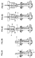
- the upper half of Fig. 4a shows a roll shaft suspending apparatus according to the present invention and the lower half shows a part of the bar and wire rod mill.
- the roll shaft suspending apparatus comprises a nozzle 115 for injecting hydraulic oil into the oil inlet 131 provided on the upper end of the roll shaft 101 of the bar and wire rod mill, a rod 116 holding on the top end thereof the nozzle 115 and having an oil feed passage 117 inside thereof connecting with the nozzle 115, and a cylinder 118 embracing the rod 116 for actuating it reciprocally by means of hydraulic oil pressure.
- the high pressurized oil is injected from the oil inlet 126 of the oil feed passage 117.
- the maximum injection pressure of the high pressurized oil is about 2000 kgf/cm 2 and it is preferred to set a certain pressure to cause the deformation of the tapered surface within its elastic limit.
- the rod 116 pushes down the roll shaft 101.
- the rod 116 lifts up the roll shaft 101.
- the nozzle 115 on the top end portion of the rod 116 may be fixed in place by a screw or the like. However, as described in this example, it is preferable to hold the nozzle in place with a resilient seat 125, such as a compression spring or a hydraulic cylinder, because the shock generated upon the injection of the high pressurized oil can be minimised more effectively.
- a resilient seat 125 such as a compression spring or a hydraulic cylinder
- a pushing jig for transmitting the pushing force.
- the push ring 119 shown in Fig. 4b is an example of such use.
- Ring fitting hole 121 corresponds to the pushing jig receiving member.
- the roll shaft suspending apparatus further comprises essentially a suspension jig engaging with the suspension jig receiving member provided on the end portion of the roll shaft.
- a circumferential groove 122 which acts as the suspension jig receiving member and a groove fitting pawl plate 123 which acts as the suspension jig to be engaging with the receiving member are illustrated in Fig. 4a.
- the use of this suspension jig on the lower end of the rod (116) makes it possible to lift up the roll shaft 101, having been disengaged from the interference fit with the ring roll 102, by means of the upward pulling force of the hydraulic cylinder 118.
- the groove fitting pawl plate 123 is, for example, preferably an arc shaped half as shown in Fig. 5.
- the roll shaft suspending apparatus according to the present invention is preferably fixed to a mount base 127 as shown in Fig. 4a, having a rigid and firm construction of steel frames or the like.
- the disassembling process of the housing can be dispensed with so that the time needed for changing the roll is reduced and the labor cost can be cut down.
- the conventional method for changing the roll involves the disassembly of the housing and therefore needs a housing disassembling apparatus and a roll changing apparatus, whereas the present invention only requires the roll changing apparatus and therefore the number of equipment stocks are reduced.
- the handling subject was conventionally a roll assembly, but the present invention involves ring rolls, thereby making the subject light weight so that the safety aspect is improved.
- the changing operation of the ring rolls can be performed within a single apparatus. Therefore, the operability and the work efficiency are improved and the working space can be reduced.
- the tapered surfaces of the inside of the ring rolls and the journal part of the roll shaft for the ring rolls are under the pressure of the injected hydraulic oil, the pressure in sliding at the engagement surface is low and the surface is well lubricated. Therefore, the tapered surface is free from abrasion or deformation and the machine can be maintained in a sound condition for a long time. As a result, the lifetimes of the components are extended and the problem caused by insufficient torque rarely happens.
Landscapes
- Engineering & Computer Science (AREA)
- Mechanical Engineering (AREA)
- Reduction Rolling/Reduction Stand/Operation Of Reduction Machine (AREA)
- Paper (AREA)
- Metal Rolling (AREA)
Abstract
Description
(Assembling Operation)
Claims (9)
- A method for changing ring rolls in a bar and wire rod mill having a plurality of roll assemblies incorporated into a housing (8) and arranged in equiangular positions around a pass (16), characterized by comprising the steps of:disengaging a spent ring roll (2) and its roll shaft (1) from interference fit;withdrawing the spent ring roll (2) by moving the roll shaft (1) in the axial direction;changing the spent ring roll (2) for a new ring roll in the housing (8);inserting the roll shaft (1) into the new ring roll; andengaging the new ring roll and the roll shaft in interference fit each other.
- The method according to claim 1, wherein hydraulic oil pressure is used for engaging and disengaging the ring roll and the roll shaft in and from interference fit.
- The method according to claim 2, further comprising the steps of:holding the roll shaft (1) of the roll assembly, in which the spent roll is to be changed, in an upright position before disengaging the spent ring roll and the roll shaft from the interference fit; andcoupling a suspending apparatus with one end of the roll shaft (1) and connecting a hydraulic oil passage within the roll shaft (1) to a hydraulic oil source through said end of the roll shaft before withdrawing the roll shaft (1) from the spent ring roll (2).
- A bar and wire rod mill comprising a plurality of roll assemblies each having a ring roll (2) capable of engaging and disengaging a roll shaft (1) in and from interference fit, wherein the roll shaft (1) is movable in the axial direction within a housing (8), said plurality of roll assemblies being arranged in equiangular positions around a pass (16) and supported by said housing (8).
- The bar and wire rod mill according to claim 4, wherein each roll assembly comprises:a mechanism for engaging or disengaging the ring roll (2) and the roll shaft (1) in and from interference fit by means of hydraulic oil, with the inner surface of the ring roll (2) and the journal part (1A) of the roll shaft (1) having a tapered surface;hydraulic oil passage extending through the roll shaft (1) from one end portion of the roll shaft (1); anda hydraulic oil inlet (12A) and a suspension jig receiving member(122) provided on one end of the roll shaft (1).
- The bar and wire rod mill according to claim 5 and further including a roll shaft suspending apparatus comprising a nozzle (14B)(115) for injecting oil into the oil inlet (12A)(131) provided on one end portion of the roll shaft (1)(101) of the roll assembly, a rod (116) holding said nozzle (14B)(115) and having a hydraulic oil passage (117) therethrough connecting with said nozzle (14B)(115), a cylinder (118) embracing said rod (116) for actuating it reciprocally by means of hydraulic oil pressure and a suspension jig member (123) on the lower end of said rod (116), and a suspension jig receiving member (22)(122) provided on said end portion of the roll sahft.
- The bar and wire rod mill according to claim 4, 5 or 6 wherein there are four roll assemblies.
- A roll shaft (1) suspending apparatus comprising:a nozzle (115) for injecting hydraulic oil into an oil inlet (12A)(131) provided on one end portion of a roll shaft (1)(101) of a roll assembly;a rod (116) holding said nozzle (14B)(115) on the top end portion thereof and having a hydraulic oil passage (117) therethrough connecting with said nozzle (14B)(115);a cylinder (118) embracing said rod (116) for actuating it reciprocally by means of hydraulic oil pressure; anda suspension jig (123) for engaging with a suspension jig receiving member (22)(122) provided on one end of said roll shaft (101).
- The roll shaft suspending apparatus according to claim 8, wherein said rod (116) holds said nozzle (115) through a resilient seat (125).
Applications Claiming Priority (4)
| Application Number | Priority Date | Filing Date | Title |
|---|---|---|---|
| JP2000258800 | 2000-08-29 | ||
| JP2000258800A JP2002066614A (en) | 2000-08-29 | 2000-08-29 | Strip rolling mill |
| JP2000330941 | 2000-10-30 | ||
| JP2000330941A JP2002137009A (en) | 2000-10-30 | 2000-10-30 | Strip roll remover |
Publications (2)
| Publication Number | Publication Date |
|---|---|
| EP1184095A2 true EP1184095A2 (en) | 2002-03-06 |
| EP1184095A3 EP1184095A3 (en) | 2003-07-16 |
Family
ID=26598674
Family Applications (1)
| Application Number | Title | Priority Date | Filing Date |
|---|---|---|---|
| EP01304161A Withdrawn EP1184095A3 (en) | 2000-08-29 | 2001-05-09 | Method and apparatus for interchanging ring rolls of a bar and wire rod mill |
Country Status (6)
| Country | Link |
|---|---|
| US (1) | US20020134127A1 (en) |
| EP (1) | EP1184095A3 (en) |
| KR (1) | KR20020060719A (en) |
| AU (1) | AU2001232224A1 (en) |
| TW (1) | TW480194B (en) |
| WO (1) | WO2002018070A1 (en) |
Cited By (2)
| Publication number | Priority date | Publication date | Assignee | Title |
|---|---|---|---|---|
| EP1849535A1 (en) * | 2006-04-27 | 2007-10-31 | SMS Meer GmbH | Roll stand |
| CN103071681A (en) * | 2013-01-21 | 2013-05-01 | 天津惠利通钢管有限公司 | Rapid roll changing device for transmission shaft of welded pipe unit |
Families Citing this family (3)
| Publication number | Priority date | Publication date | Assignee | Title |
|---|---|---|---|---|
| DE20320404U1 (en) * | 2002-09-30 | 2004-06-24 | Kocks Technik Gmbh & Co | Roll stand for rolling rod or tubular material |
| CN112427921B (en) * | 2020-11-24 | 2023-02-10 | 太原钢铁(集团)有限公司 | Device and method for dismantling floating shaft of hot rolling roughing mill |
| TWI844371B (en) * | 2023-05-22 | 2024-06-01 | 中國鋼鐵股份有限公司 | Disassembly method for rolls |
Family Cites Families (7)
| Publication number | Priority date | Publication date | Assignee | Title |
|---|---|---|---|---|
| DE977216C (en) * | 1951-01-30 | 1965-06-24 | Demag Ag | Rolling mill stand |
| JPS5847301U (en) * | 1981-09-25 | 1983-03-30 | 住友金属工業株式会社 | Sleeve attachment/detachment roll |
| JPS5876328U (en) * | 1981-11-18 | 1983-05-23 | 日本鋼管株式会社 | Roll recombination device |
| EP0613738B1 (en) * | 1990-10-03 | 1999-01-20 | Nippon Steel Corporation | Apparatus for securing a work roll in a rolling mill |
| DE4432084C2 (en) * | 1994-09-09 | 1997-06-26 | Kocks Technik | Process and tool for removing and installing a rolling ring |
| US6016679A (en) * | 1997-09-30 | 2000-01-25 | Sumitomo Heavy Industries, Ltd. | Rolling mill |
| JP3270724B2 (en) * | 1997-09-30 | 2002-04-02 | 住友重機械工業株式会社 | Roll mill |
-
2001
- 2001-01-31 KR KR1020027005331A patent/KR20020060719A/en not_active Withdrawn
- 2001-01-31 WO PCT/JP2001/000665 patent/WO2002018070A1/en not_active Ceased
- 2001-01-31 US US10/110,756 patent/US20020134127A1/en not_active Abandoned
- 2001-01-31 AU AU2001232224A patent/AU2001232224A1/en not_active Abandoned
- 2001-02-02 TW TW090102252A patent/TW480194B/en not_active IP Right Cessation
- 2001-05-09 EP EP01304161A patent/EP1184095A3/en not_active Withdrawn
Cited By (3)
| Publication number | Priority date | Publication date | Assignee | Title |
|---|---|---|---|---|
| EP1849535A1 (en) * | 2006-04-27 | 2007-10-31 | SMS Meer GmbH | Roll stand |
| US7469566B2 (en) | 2006-04-27 | 2008-12-30 | Sms Meer Gmbh | Roll stand |
| CN103071681A (en) * | 2013-01-21 | 2013-05-01 | 天津惠利通钢管有限公司 | Rapid roll changing device for transmission shaft of welded pipe unit |
Also Published As
| Publication number | Publication date |
|---|---|
| KR20020060719A (en) | 2002-07-18 |
| AU2001232224A1 (en) | 2002-03-13 |
| TW480194B (en) | 2002-03-21 |
| US20020134127A1 (en) | 2002-09-26 |
| EP1184095A3 (en) | 2003-07-16 |
| WO2002018070A1 (en) | 2002-03-07 |
Similar Documents
| Publication | Publication Date | Title |
|---|---|---|
| CN208976508U (en) | Roller mill roll bending and shifting device | |
| US4791803A (en) | Die-change device for a multi-stage forming machine | |
| JP2810557B2 (en) | Rolling equipment combining special steel rolling path and wire rod rolling path | |
| JPH11254005A (en) | Improved 6-high rolling mill with side support | |
| US20020134127A1 (en) | Ring roll replacing method in bar steel rolling mill and device therefor | |
| US4305678A (en) | Coupling for a mill roll | |
| CN120920517A (en) | Quick-response high-precision prestress rolling mill and control method | |
| US3825387A (en) | Quick-change die and roller assembly | |
| CN115175775B (en) | Mechanical high-speed roll changing system used in conjunction with robotic roll changing system | |
| KR101320759B1 (en) | Apparatus for Separating Spindle of Rolling machine | |
| CN100368103C (en) | Rolling mill seat capable of being taken apart into interchangeable modules | |
| JP2609235B2 (en) | A device for moving the work roll in the axial direction | |
| US3911550A (en) | Quick-change die and roller assembly | |
| EP0298675B1 (en) | Sleeve mounting and removal tool | |
| US5113623A (en) | Method and apparatus for grinding the work rolls of a planetary rolling mill | |
| US20040020259A1 (en) | Roll changing device in rolling mill | |
| SU1690869A1 (en) | Rolling mill vertical stand | |
| RU2068312C1 (en) | Device for changing horizontal stands | |
| CN111941027A (en) | Grinding roller dismounting device and method | |
| JPH0137764Y2 (en) | ||
| JP2966230B2 (en) | Roll thrust ring and its mounting structure in rolling mill | |
| RU2033287C1 (en) | Spindle joint of drive unit of rolling stand | |
| CN220225490U (en) | Sliding baffle type connector | |
| CN114602974B (en) | Jaw type cold-rolled winding drum | |
| JP2002066614A (en) | Strip rolling mill |
Legal Events
| Date | Code | Title | Description |
|---|---|---|---|
| PUAI | Public reference made under article 153(3) epc to a published international application that has entered the european phase |
Free format text: ORIGINAL CODE: 0009012 |
|
| AK | Designated contracting states |
Kind code of ref document: A2 Designated state(s): AT BE CH CY DE DK ES FI FR GB GR IE IT LI LU MC NL PT SE TR |
|
| AX | Request for extension of the european patent |
Free format text: AL;LT;LV;MK;RO;SI |
|
| PUAL | Search report despatched |
Free format text: ORIGINAL CODE: 0009013 |
|
| AK | Designated contracting states |
Designated state(s): AT BE CH CY DE DK ES FI FR GB GR IE IT LI LU MC NL PT SE TR |
|
| AX | Request for extension of the european patent |
Extension state: AL LT LV MK RO SI |
|
| 17P | Request for examination filed |
Effective date: 20030822 |
|
| RAP1 | Party data changed (applicant data changed or rights of an application transferred) |
Owner name: JFE STEEL CORPORATION |
|
| STAA | Information on the status of an ep patent application or granted ep patent |
Free format text: STATUS: THE APPLICATION HAS BEEN WITHDRAWN |
|
| 18W | Application withdrawn |
Effective date: 20031231 |